© 2017, IRJET | Impact Factor value: 5.181 | ISO 9001:2008 Certified Journal
| Page 1113
ENHANCEMENT OF DYNAMIC STABILITY AND VOLTAGE CONTROL OF A
GRID-CONNECTED OFFSHORE WIND FARM AND MARINE- CURRENT FARM USING A
STATCOM
T.RADHA
1, M. SHOBHA
2, B.NARENDRA
3, K.SWETHA
41
PG Scholar, MTECH (PE), CVRT, Andhrapradesh, India
2
Associate Professor & HOD, Dept of EEE, CVRT, Andhrapradesh, India
3,4
Assistant Professor, Dept of EEE, Andhrapradesh, India
---***---Abstract: -
This venture shows a control plot in view of a static synchronous compensator (STATCOM) to accomplish both voltage control and damping improvement of a grid-associated incorporated 80-MW offshore wind farm (OWF) and 40-MW marine-current farm (MCF). The execution of the contemplated OWF is reproduced by an equal doubly-fed induction generator (DFIG) driven by a proportional wind turbine (WT) while a comparable squirrel-confine rotor induction generator (SCIG) driven by an equal marine-current turbine (MCT) is utilized to recreate the qualities of the MCF. A damping controller of the STATCOM is planned by utilizing modular control hypothesis to contribute powerful damping attributes to the considered system under various working conditions. A frequency-area approach in view of a changed system display utilizing Eigen esteem strategies and a period space plot in view of a nonlinear system show subject to different unsettling influences are both utilized to reenact the adequacy of the proposed control conspire. It can be finished up from the reproduced comes about that the proposed STATCOM joined with the outlined damping controller is extremely successful to settle the contemplated system under aggravation conditions. The voltage fluctuations of the AC bus subject to the dynamic power varieties of the contemplated system can likewise be viably controlled by the proposed control plot.INTRODUCTION
A wind turbine is a device that believers kinetic energy from the wind into mechanical energy. In the event that the mechanical energy is utilized to create electricity, the device might be known as a wind generator or wind charger. In the event that the mechanical energy is utilized to drive hardware, for example, for granulating grain or pumping water, the device is known as a windmill or wind pump. Produced for over a thousand years, the present wind turbines are fabricated in a scope of vertical and even pivot sorts. The littlest turbines are utilized for applications, for example, battery charging or helper power
on cruising pontoons; while vast grid-associated varieties of turbines are turning into an inexorably extensive wellspring of business electric power.
© 2017, IRJET | Impact Factor value: 5.181 | ISO 9001:2008 Certified Journal
| Page 1114
turbines for power era from wind and are associated witheach other in the diverse way is called wind farm. Fundamentally wind farm comprises of many wind turbines that are associated with each other to create little measure of electric power. Distinctive methodologies are utilized to fabricate the wind farms in various areas or range. Generators driven by marine-current turbine (MCT) consolidated with offshore generators driven by wind turbine (WT) will turn into a novel plan for energy creation later on. Since seas cover over 70% surface of the earth, a half breed power era system containing both offshore wind farm (OWF) and marine-current farm (MCF) can be broadly created at the particular areas of the world later on. One of the straightforward techniques for running an OWF is to interface the yield terminals of a few DFIGs together and after that associate with a power grid through an offshore stride up transformer and undersea links. To run a MCF may utilize a few Permanent Magnets synchronous generators (PMSGs) associated specifically to the power grid through an offshore stride up transformer and undersea links
Both wind energy and sea energy have been coordinated together in the U.K. Sea energy may incorporate warm energy, wave energy, offshore wind energy, tidal energy, sea current energy, and so forth. Generators driven by marine-current turbine (MCT) consolidated with offshore generators driven by wind turbine (WT) will turn into a novel plan for energy creation later on. Since seas cover over 70% surface of the earth, a cross breed power era system containing both offshore wind farm (OWF) and marine-current farm (MCF) can be widely created at the particular areas of the world later on. One of the basic strategies for running an OWF is to interface the yield terminals of a few DFIGs together and after that associate with a power grid through an offshore stride up transformer and undersea links. To run a MCF may utilize a few squirrel-confine induction generators (SCIGs) associated specifically to the power grid through an offshore stride up transformer and undersea links. Both WTs and MCTs have fundamentally the same as working attributes yet a SCIG-based MCF requires receptive power for polarization while a DFIG-based OWF with two bi-directional power converters can control its yield power factor to be near solidarity. At the point when the produced dynamic power of a SCIG-based MCF is shifted because of marine-current fluctuations, the consumed responsive power and the terminal voltage of the MCF can be altogether influenced. In case of expanding grid unsettling influences, e.g., grid blames, an energy stockpiling system
or a control device for a substantial scale highcapacity power era system is by and large required to repay fluctuating segments when associating with a power grid. An extensive scale OWF may join with various FACTS devices or energy-stockpiling systems, for example, a STATCOM, and so on. The broke down consequences of security change of power systems utilizing STATCOMs and the damping controller outline of STATCOMs were displayed. The outline of a yield input straight quadratic controller for a STATCOM and a variable-sharp edge pitch of a wind energy transformation system to perform both voltage control and mechanical power control under grid-association or islanding conditions. System displaying and controller outline for quick load voltage direction and alleviation of voltage flash utilizing a STATCOM were illustrated. Another D-STATCOM control calculation empowering separate control of positive-and negative-sequence currents was proposed, and the calculation depended on the created numerical model in the directions for a DSTATCOM working under uneven conditions
DOUBLE FED INDUCTION GENERATOR (DFIG)
DFIG is an abbreviation for Double Fed Induction Generator, a generating principle widely used in wind turbines. It is based on an induction generator with a multiphase wound rotor and a multiphase slip ring assembly with brushes for access to the rotor windings. It is possible to avoid the multiphase slip ring assembly, but there are problems with efficiency, cost and size.
PERMANENT MAGNET SYNCHRONOUS MACHINE
© 2017, IRJET | Impact Factor value: 5.181 | ISO 9001:2008 Certified Journal
| Page 1115
frequently introduced in power systems exclusively forpower factor remedy. The armature winding of a customary synchronous machine [3] is perpetually on the stator and is generally a three stage winding. The field winding is for the most part on rotor and energized by dc current, or changeless magnets. The dc power supply required for excitation for the most part is provided through a dc generator known as exciter, machine which is frequently mounted on an indistinguishable shaft from the synchronous.
Fig1: Doubley fed induction generator
The dynamic crowbar can evacuate the rotor short controlledly and in this way the rotor side converter can be begun simply after 20-60 ms from the begin of the grid unsettling influence. Along these lines it is conceivable to produce responsive current to the grid amid whatever remains of the voltage plunge and thusly help the grid to recuperate from the blame. A doubly fed induction machine is an injury rotor doubly-fed electric machine and has a few preferences over a traditional induction machine in wind power applications. Initially, as the rotor circuit is controlled by a power hardware converter, the induction generator can both import and fare responsive power. This has critical consequences for power system steadiness and enables the machine to help the grid amid serious voltage unsettling influences (low voltage ride through, LVRT). Second, the control of the rotor voltages and currents empowers the induction machine to stay synchronized with the grid while the wind turbine speed changes. A variable speed wind turbine uses the accessible wind asset more effectively than a settled speed wind turbine, particularly amid light wind conditions. Third, the cost of the converter is low when contrasted and other variable speed arrangements in light of the fact that lone a small amount of the mechanical power, ordinarily 25-30 %, is fed to the grid through the converter, the rest being fed to grid straightforwardly from the stator. The productivity of the DFIG is useful for a similar reason.
MODELS OF THE OFF SHORE WIND FARM AND MARINE CURRENT FARM
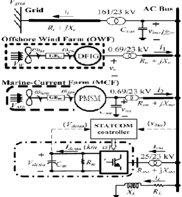
Figure demonstrates the structure of the concentrated coordinated DFIG based OWF and PMSG based MCF with the proposed STATCOM. The 80MW OWF is spoken to by a huge equal collected DFIG driven by an identical amassed variable speed WT through an equal accumulated gearbox. The 40MW MCF is spoken to by an expansive proportional accumulated PMSG driven by an equal collected variable speed MCT through an identical totaled gearbox. The OWF, the MCF, the STATCOM and a neighborhood stack are associated with an AC bus that is fed to the coastal power grid through an offshore stride up transformer and undersea links [9]. The utilized numerical models of the contemplated system are depicted as beneath.
Fig2 Composition of the integrated OWF and MCF with STATCOM
[image:3.595.344.530.323.524.2]© 2017, IRJET | Impact Factor value: 5.181 | ISO 9001:2008 Certified Journal
| Page 1116
MARINE-CURRENT SPEED AND MARINE-CURRENT [image:4.595.81.247.148.282.2]TURBINE MODEL
Fig.3.Control block diagram of the proposed STATCOM including the designed PID damping controller
STRUCTURE OF STATCOM
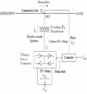
[image:4.595.78.228.484.645.2]Basically, STATCOM is contained three basic parts (as seen from Figure underneath): a voltage source converter (VSC), a phase up coupling transformer, and a controller. In a high-voltage system, the spillage inductances of the movement up power transformers can fill in as coupling reactors. The major inspiration driving the coupling inductors is to filter through the current consonant parts that are created mainly by the throbbing yield voltage of the power converters
Fig 4 structure of STATCOM
The controller of a STATCOM works the converter especially that the stage edge between the converter voltage and the transmission line voltage is powerfully balanced and synchronized so that the STATCOM creates or retains fancied VAR at the purpose of coupling association. Figure demonstrates an improved graph of the STATCOM with a converter voltage source
DESIGN OF A PID DAMPING CONTROLLER FOR STATCOM USING MODAL CONTROL THEORY
This section presents a unified approach based on modal control theory to design the PID damping controller of the proposed STATCOM shown in Figure. For dynamic stability improvement of the studied system. The nonlinear system equations developed in Section II are first linearized around a nominal operating point to obtain a set of linearized system equations in matrix form of
PX = AX+BU+VW
Y = CX+DU
STATCOM is a controlled receptive power source. It gives voltage bolster by producing or engrossing responsive power at the purpose of normal coupling without the need of extensive outer reactors or capacitor banks. Utilizing the controller, the VSC and the coupling transformer, the STATCOM operation is delineated in Figure 8.The one-line chart of the contemplated STATCOM was appeared in Figure 8. The per unit q-pivot and - hub yield voltages of STATCOM can be communicated by, separately
V
qsta=V
dcsta.K
m.cos (
bus+
α)
V
dsta= V
dcsta. K
m.sin (
bus+
α)
© 2017, IRJET | Impact Factor value: 5.181 | ISO 9001:2008 Certified Journal
| Page 1117
Fig 5 STATCOM operating in inductive or capacitivemodes
[image:5.595.316.579.269.547.2]STATCOM operating in inductive or capacitive modes In other words, looking at the phasor diagrams on the right of Figure 3.4, when1I, the reactive current component of the STATCOM, leads (THVE−1) by 90º, it is in inductive mode and when it slacks by 90º, it is in capacitive mode. This double mode ability empowers the STATCOM to give inductive pay and capacitive remuneration to a system. Inductive remuneration of the STATCOM makes it exceptional. This inductive remuneration is to give inductive reactance when overcompensation because of capacitors banks happens. This occurs amid the night, when a regular inductive load is around 20% of the full load, and the capacitor banks along the transmission line give inordinate capacitive reactance because of the lower stack. Essentially the control system for a STATCOM comprises of a current control and a voltage control.
[image:5.595.59.254.498.689.2]STEADY-STATE ANALYSIS UNDER VARIOUS OPERATING CONDITIONS
Fig.6: Steady-state operating conditions of the studied system under various values of wind speed and
marine-current
SIMULATION RESULTS
In this area, to demonstrate the standard of power control of PMSG-based variable-speed wind turbine associated with the grid, it is controlled keeping in mind the end goal to catch the most extreme wind energy and its conduct subjected to a variable speed wind will be shown utilizing numerical recreations conveyed under the Matlab - SIMULINK. The damping attributes contributed by the proposed STATCOM joined with the planned PID damping controller to showing signs of improvement dynamic soundness change of the contemplated system
© 2017, IRJET | Impact Factor value: 5.181 | ISO 9001:2008 Certified Journal
| Page 1118
Fig: 8 Dynamic responses of the studied system withoutthe STATCOM damping controller under a noise wind speed disturbance
Fig.9 Dynamic responses of the studied system with and without the designed PID STATCOM damping controller
© 2017, IRJET | Impact Factor value: 5.181 | ISO 9001:2008 Certified Journal
| Page 1119
Fig:10 Dynamic responses of the studied system with© 2017, IRJET | Impact Factor value: 5.181 | ISO 9001:2008 Certified Journal
| Page 1120
Fig.11. Transient responses of the studied system withand without the designed PID STATCOM damping controller under a three-phase fault at power grid.
CONCLUSION
This venture has displayed the dynamic security change of an incorporated OWF and MCF utilizing a STATCOM. A PID damping controller has been intended for the STATCOM by utilizing a unified approach in light of post task approach. Eigen esteem computations and time-space reproductions of the contemplated framework subject to a clamor wind-speed unsettling influence, a marine-current wind-speed aggravation, and a three-stage impede at the grid have been methodicallly performed to show the viability of the proposed STATCOM joined with the composed PID damping controller on smothering voltage fluctuation of the examined framework and enhancing framework dynamic strength under various working conditions. It can be finished up from the reproduction comes about that the proposed STATCOM joined with the composed PID damping controller is equipped for enhancing the
execution of the concentrated incorporated OWF and MCF under various working conditions.
REFERENCES
[1] S. E. B. Elghali, R. Balme, K. L. Saux, M. E. H. Benbouzid, J. F. Charpentier, and F. Hauville, “A simulation model for the evaluation of the electrical power potential harnessed by a marine current turbine,” IEEE J. Ocean. Eng., vol. 32, no. 4, pp. 786–797, Oct. 2007.
[2] W. M. J. Batten, A. S. Bahaj, A. F. Molland, and J. R. Chaplin, “Hydrodynamics of marine current turbines,” Renewable. Energy, vol. 31, no. 2, pp. 249–256, Feb. 2006.
[3] L. Myers and A. S. Bahaj, “Simulated electrical power alderney race,” Renewable. Energy, vol. 30, no. 11, pp. 1713–1731, Sep. 2005.
[4] H. Chong, A. Q. Huang, M. E. Baran, S. Bhattacharya, W. Litzenberger, L. Anderson, A. L. Johnson, and A. A. Edris, “STATCOM impact study on the integration of a large wind farm into a weak loop power system,” IEEE Trans. Energy Convers., vol. 23, no. 1, pp. 226–233, Mar. 2008.
[5] H. Gaztanaga, I. Etxeberria-Otadui, D. Ocnasu, and S. Bacha, “Real-time analysis of the transient response improvement of fixed-speed wind farms by using a reduced-scale STATCOM prototype,” IEEE Trans. Power Syst., vol. 22, no. 2, pp. 658–666, May 2007.
[6] K. R. Padiyar and N. Prabhu, “Design and performance evaluation of sub synchronous damping controller with STATCOM,” IEEE Trans. Power Del., vol. 21, no. 3, pp. 1398–1405, Jul. 2006.
[7] W. L. Chen and Y. Y. Hsu, “Controller design for an induction generator driven by a variable-speed wind turbine,” IEEE Trans. Energy Convers., vol. 21, no. 3, pp. 635–625, Sep. 2006.
[8] A. Jain, K. Joshi, A. Behal, and N. Mohan, “Voltage regulation with STATCOMs: Modeling, control and `,” IEEE Trans. Power Del., vol. 21, no. 2, pp. 726–735, Apr. 2006.
[9] B. Blˇazˇic and I. Papic, “Improved D-STATCOM control for operation with unbalanced currents and voltages,” IEEE Trans. Power Del., vol. 21, no. 1, pp. 225–233, Jan. 2006.
© 2017, IRJET | Impact Factor value: 5.181 | ISO 9001:2008 Certified Journal
| Page 1121
SSSC,” IEEE Trans. Power Del., vol. 20, no. 1, pp. 435–442,Jan. 2005.
[11] K. V. Patil, J. Senthil, J. Jiang, and R. M. Mathur, “Application of STATCOM for damping torsinal oscillations in series compensated AC system,” IEEE Trans. Energy Convers., vol. 13, no. 3, pp. 237–243, Sep. 1998.
[12] N. Mithulananthan, C. A. Canizares, J. Reeve, and G. J. Rogers, “Comparison of PSS, SVC, and STATCOM controllers for damping power system oscillations,” IEEE Trans. Power Syst., vol. 18, no. 2, pp. 786–792, May 2003.
[13] P. Rao, M. L. Crow, and Z. Yang, “STATCOM control for power system voltage control applications,” IEEE Trans. Power Del., vol. 15, no. 4, pp. 1311–1317, Oct. 2000.
[14] Y. Ye, M. Kazerani, and V. H. Quintana, “Current-source converter based STATCOM: Modeling and control,” IEEE Trans. Power Del., vol. 20, no. 2, pp. 795–800, Apr. 2005.
[15] Z. Yang, C. Shen, L. Zhang, M. L. Crow, and S. Atcitty, “Integration of a STATCOM and battery energy storage,” IEEE Trans. Power Syst., vol. 16, no. 2, pp. 254–260, May 2001.
AUTHORS
1. T.RADHA. She completed her professional career of education in B.Tech (EEE) pursuing M.Tech from CVRT Anantapur(AP).She is interested in Power Electronics
2. M. SHOBHA has completed her professional career of education in B.Tech (EEE). She obtained M.Tech degree. At present working as an Associate Professor and Head of the EEE Department in CVRT Anantapuramu district (AP).
3. B.NARENDRA has 4 years’ experience in teaching in graduate and post graduate level and he presently working as Assistant professor in department of EEE.