© 2017, IRJET | Impact Factor value: 5.181 | ISO 9001:2008 Certified Journal | Page 441
TOOL LIFE MANAGEMENT FOR CNC MACHINE
Shailendra Patil
1, Saurabh Pawar
2, Akshay Karanke
3, Ajinkya Parkhi
4, Anil Thombre
5, Sanket
Hingankar
61,2,3,4 ,5
UG Student, Department of Mechanical Engineering, Anantrao Pawar college of engineering & Research,
Maharashtra, India
6
Professor, Department of Mechanical Engineering, Anantrao Pawar college of engineering & Research,
Maharashtra, India
---***---Abstract - The output from a computer numerical controlmachine tool can be increased to a large extent by using a tool life management system if and when the tool life management system is applied or implemented properly. When considering whether the system is right for the given applications, we consider that the ultimate goal of any tool life management system is to keep all tool maintenance offline. Tool maintenance includes any task done to keep tools cutting on size (measuring work pieces and sizing tools) as well as any task performed when tools get dull (tool/insert replacement, re-measuring program zero, trial machining, and more). By doing tool maintenance offline, the task must be done in conjunction with the production run, while the machine is in cycle. The design of machine should be done in such a way that a tool can easily and safely removed and replaced while performing the maintenance of the machine and the machine is running so as to neglect the unproductive time.
Key Words: Data Analysis for Tool Life, Tool usage per day, No. of Tool pre-setting, No. of Tool changes etc. 1. INTRODUCTION
With a proper, effective and efficient application, tool life management systems can increase the output from CNC machine tool to a great extent. While considering the fact that whether the system is suitable for various applications of tool life management systems, it is quite essential as well as necessary to keep all tool maintenances offline. Tool maintenances include the tasks of keeping the cutting size of tool within its range/limit, as well as it includes tasks which are required when tools get dull. By performing tool maintenance offline, the tasks are thus done in conjunction with the production run, while the machine is in cycle.
Also we need to consider a fact that tool life management in many applications could add a lot of production run time. For the matter of fact to avoid such circumstances many CNC machines, especially their turning centers are kept down while the dull cutting tools are being replaced. Thus if the tool maintenance are kept away from affecting the production run time, the jobs would get completed much faster and also the cycle time would be reduced visibly. Also tool life management do play a vital role in metal working processes, so that the information regarding the tool can be
uniformly managed or organized. Tool life management in general deals with two major parts which include documentation and transaction data; where the documentation handles the information required for trouble and impactful production processes. Tool life management provides flexibility in its working system by its ability of modifying the feeds and cutting speeds based on cutting tool material required for metal working processes. Thus due to this several functions such as processing, modifying, documenting ,managing etc. together as a whole can be handled through tool life management.
1.1 METHODOLOGY
Fig-1: Flow Chart for Tool –Life Management 1.2 Tool-Life Definition
1. The tool life is the duration of actual cutting time after which the tool is no longer usable.
2. There are many ways of defining the tool life and the common way of quantifying the end of a tool life is by a limit on the maximum acceptable flank wear. 3. With a good application and when properly applied,
a tool life management system can dramatically increase for a CNC machine tool.
© 2017, IRJET | Impact Factor value: 5.181 | ISO 9001:2008 Certified Journal | Page 442 tools cutting on size as well as any task performed
when tools get dull.
5. Ultimate goal of Tool life management is to keep all tools offline. Thus by keeping tools offline all tasks should be done in conjunction in production run, while machine is in cycle.
2. TOOL DESCRIPTION FOR VARIOUS MODELS Table -1:
MODEL NUMBER TOOL DESCRIPTION
JZ/Sprint/JV/BM100 Dia 9.5 x 25 mm Drill cum face spot (Spark Plug Hole)
B104D Dia 2mm Drill
K1K2 M10x1 Tap
K11 Dia 7x45 Step Drill
Super 100 Dia 9 x 100 x 160 mm Drill
Ku Head Dia 8mm drill
Lombordini Block Dia 8.5 X 10 X 117 mm Drill (clamping hole)
M4WL Dia 8.5mm WIDIA TC drills
Piaggio Dia 8 mm End Drill Manifold Dia 9.15 End mill
Flange Dia 4 mm Gun Drill
MMAC1, AC2 Dia 11.95 x 15.17 mm hole mill
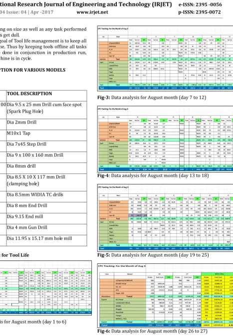
2.1 Data Analysis for Tool Life
[image:2.595.113.581.47.722.2]Fig-2: Data analysis for August month (day 1 to 6)
Fig-3: Data analysis for August month (day 7 to 12)
[image:2.595.36.293.228.541.2]Fig-4: Data analysis for August month (day 13 to 18)
Fig-5: Data analysis for August month (day 19 to 25)
Fig-6: Data analysis for August month (day 26 to 27) The above mentioned excel sheet consist of the following parameters for analysis: -
© 2017, IRJET | Impact Factor value: 5.181 | ISO 9001:2008 Certified Journal | Page 443 It basically refers to the number of products that
were produced in a day. It is based on the working capacity of the tool life and its functionality. 2. Tool Cost
It is basically based on production and it is the estimation cost of the tool required for producing products in a single day.
3. CPC
Cost per Capital is a ratio of Total Tool Cost to Production and it varies if either of the parameters changes.
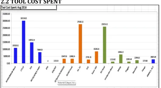
[image:3.595.47.552.82.795.2]2.2 TOOL COST SPENT
Fig-6: Data analysis for tool cost spent for month of August The above graph shows the amount of money spent on tool for performing various operations. The X axis represents the name of the component whereas Y-axis represents the cost spent on tool.
CT112 , K11, Super 100 etc. are the name of the motorcycle and the cost spent on tool is the cost of tool used to produce the parts of those motorcycles. The Manhattan of the CT112 , KL K2 and KU head is highest as seen in the graph.
2.3 TOOLING REVIEW AND PREVENTIVE MEASURE COST SPENT Table -2: MODEL NUMBE R TOOL DESCRIPTI ON CONCERN DECRIPTION / ROOT CAUSE ANALYSIS ACTION PLAN TAKEN JZ / Sprint / JV / BM100
Dia 9.5 x 25 mm Drill cum face spot (Spark Plug Hole) Quality issue (Regrinding issue) in cutting edges which creates burr sticking in the drill gashing, spot face
Informed to supplier to do the corrective measure regarding finishing and grinding.
B104D Dia 2mm
Drill Tool broken. Observation: Vc - 13m/min; tool life in mtrs. - 8 mtrs.
As a corrective action, every shift beginning - the tools are getting changed.
Tool breakage frequency is reduced.
K11 Dia 7x45
Step Drill Fully Aluminum got welded in cutting edges
Uncoated tools with polished flute to be used
Straight flute drills will have better chip evacuation Coolant pressure to be increased 2 tools were modified geometry for better Burr evacuation; performed well. Super
100 Dia 9 x 100 x 160 mm Drill
Tool broken and created abnormal noise. Burning marks observed (dry cut). When checked the machine, the coolant pipes not focused.
As like CT112 - 8.5 drill, double margin drill will be developed. (based
on the
performance of Dia. 8.5 drill, it will be done)
Lombord
ini Block Dia 8.5 X 10 X 117 mm Drill (clamping hole)
Frequent tool
breakage issue Set tool life is on higher side.
M4WL Dia 8.5mm WIDIA TC drills
Trough coolant
drills Trough drills after 2nd Re-coolant sharpening loaded on machine Drill1 = 600 Cycles, Drill 2 = 369 Cycles O/s issue, Drill 3 = 280 Cycles wear out, Drill 4 = 500Cycles Piaggio Dia 8.3 mm
Drill At exit of the hole, it is opening out in Cross Hole on the same feed
At Exit, feed rate to be reduced to 1/3 of the feed rate. Feed should be 200mm/min for 2~3mm at exit Manifold Dia 9.15
End mill Continuous breakage - Checked clamping
[image:3.595.35.301.272.417.2]© 2017, IRJET | Impact Factor value: 5.181 | ISO 9001:2008 Certified Journal | Page 444 pressure Found
50 Bar, For another machine its 40 bar, Milling cutter path need to change as its failing with clamping nut
excess load. End mill 2.Milling path changed.
Flange Dia 4 mm
Gun Drill New tool is loaded, when truing the drill - hit in the fixture got bend. Observation: When tightening the gun drill in the spindle, it deflects and rubbing inside bush
The gun drill was inserted in guide bush, and after that gun drill is tightened in the spindle.
MMAC1,
AC2 Dia 11.95 x 15.17 mm hole mill
Observation: Regrinding tools are creating problem
Check the diameter and corner chamfer.
2.4. NUMBER OF TOOL CHANGES
Fig-7: Number of Tool Changes (day 1 to 9)
Fig-8: Number of Tool Changes (day 10 to 18)
Fig-9: Number of Tool Changes (day 19 to 27)
Fig-10: Number of Tool Changes (day 28 to 31)
The above sheet shows the no. of tools changes that were made on that particular day. The above sheet is further divided into two more categories i.e. scheduled an un-scheduled
Scheduled – It is the actual no. of changes that were meant to happen as decided by the company. Those changes were compulsory and had to be done.
Un-scheduled – It is the no. of tool changes that weren’t decided but made due to some adverse conditions that were faced on that particular day. Or else the job to be done was completed before the expected time. Due to which the tool had to be changed. Thus Un-scheduled tool may be a good sign or bad depending upon the situation.
Fig-11: Graph of Data Analysis for No. of Change of Tool for un-scheduled Tooling
3. TOOL USAGE PER DAY
9.5 x 2 5 2
10 x 17 x 45 9 x 10
0 x 16 0 8
8.5 X 1
0 X 117 8.5 8.3 9.15 4 11.95
x 15.1 7 0
5 10 15
20
TOOL USAGE PER DAY
USAGE PER DAY (HOURS)
Fig-12: Graph of Tool usage per day
© 2017, IRJET | Impact Factor value: 5.181 | ISO 9001:2008 Certified Journal | Page 445 of drills used in performing operations on the component;
whereas the Y-axis represents the number of hours for which the tool is used per day.
4. CONCLUSIONS
This project provides detail knowledge and study about tool life analysis of the tools used in an industry for the month of august. It also describes the names of various tools and jobs that have been used for this project. Analysis of data of tool life is done and recorded in an excel sheet. The collected data is summarized in the form of various graphs and different results are concluded. A table of type/name of tool, reason of failure and along with the action plan taken is for the above analysis is shown in this paper.
REFERENCES
[1] N.N Mahatme and S.V Dahake, “Productive Improvement and cycle time reduction in CNC machining,” International Journal of Research in advent technology. [2] M. Hansel and T. Harnau, “Tool life and Tool quality,”
International cold forging group ICFG, 6th International Tooling Conference.
[3] Ilhan Asiltürk, Harun Akkus,” Determining the effect of cutting parameters on surface roughness in hard turning using the Taguchi method,” Science direct Measurement 44 (2011) 1697–1704.
[4] J.A. Ghani, I.A. Choudhury and H.H. Hassan, “Application of Taguchi method in the optimization of end milling parameters,” Journal of Materials Processing Technology 145 (2004) 84–92.
BIOGRAPHIES
Under graduate final year student of Savitribai Phule Pune
University, Maharashtra, India. Pursuing Mechanical Engineering (2016-2017).
Under graduate final year student of Savitribai Phule Pune
University, Maharashtra, India. Pursuing Mechanical Engineering (2016-2017).
Under graduate final year student of Savitribai Phule Pune
University, Maharashtra, India. Pursuing Mechanical Engineering (2016-2017).
Under graduate final year student of Savitribai Phule Pune
University, Maharashtra, India. Pursuing Mechanical Engineering (2016-2017).