ISSN Online: 1947-394X ISSN Print: 1947-3931
Evaluating Oblique Shock Waves Characteristics
on a Double-Wedge Airfoil
Jorge Luis Garrido Tellez1, Eusebio Hernandez-Martinez1, Miguel Toledo Velazquez2, Jose Angel Ortega Herrera2, Pedro Quinto-Diez2
1Instituto Politecnico Nacional SEPI ESIME Ticoman, Ciudad de Mexico, Mexico 2Instituto Politecnico Nacional SEPI ESIME Zacatenco, Ciudad de Mexico, Mexico
Abstract
Numerical and experimental study to evaluate aerodynamic characteristics in super-sonic ow over a double wedge airfoil is carried out using Fluent software and a su-personic wind tunnel, respectively. The Schlieren visualization method was also used to develop the experimental step of this study. The supersonic wind tunnel reached a proximately a Mach number of 1.8. The result got showed oblique shock waves visu-alization on double-wedge airfoil and the numerical simulation, the flow behavior as function of Mach number, pressure, temperature and density in the flow field on the computational model. The simulation allowed to observe the shock wave and the expansion fan in the leading and tailing edge of double-wedge airfoil. From the nu-merical and experimental comparison, an agreement at the shock wave angle and Mach number was observed, with a difference about 1.17% from the experimental results.
Keywords
Oblique Shock Waves, Supersonic Airfoil, Flow Visualization, Numerical Simulation, Schlieren Method
1. Introduction
It is very relevant to understand the compressible fluid ow and some phenomenon pre-sented in compressible ow turbomachines, blades cascades, aeronautics, aerodynamics and in any fluid motion where exist high ow velocities. Traditionally, supersonic airfoils are classified into two types, namely double wedge and bi-convex airfoils. In internal and external flows at high velocities, normal and oblique shock waves formation are presented. The shock waves generate irreversibilities and discontinuities in the flow,
How to cite this paper: Tellez, J.L.G., nandez-Martinez, E., Velazquez, M.T., Her-rera, J.A.O. and Quinto-Diez, P. (2016) Eva- luating Oblique Shock Waves Characteris-tics on a Double-Wedge Airfoil. Engineer-ing, 8, 862-871.
http://dx.doi.org/10.4236/eng.2016.812078
Received: September 6, 2016 Accepted: December 19, 2016 Published: December 22, 2016 Copyright © 2016 by authors and Scientific Research Publishing Inc. This work is licensed under the Creative Commons Attribution International License (CC BY 4.0).
vibration and aeroacoustics noise [1]. These singularities increase the drag which is undesirable in the supersonic flow field. Although the shock waves thickness is about 2 µm, there are accelerations and sudden changes in fluid properties like velocity, pres-sure, temperature and density. If the flying object is a long with sharp wedge front, a steady oblique shock wave will be generated. The oblique shock wave produced by a three dimensional wing has been analyzed in [2] [3] [4]. The linear stability of oblique shock waves has been studied in [5], the author studied the stability with respect to small perturbation in the incoming ow and in the solid surface. Recently, double wedge airfoils are designed to have a better lift to drag ratio when compared to subsonic pro-files in supersonic flight [6]. In fact, this type of wing profiles performs quite excellent in the supersonic flight regime but would lead to disastrous performance at low speed due to those singularities [7]. In Ref. [8] a study on the aerodynamic response of double wedge airfoil in supersonic ow with free stream Mach number is presented, they varied the angle of attack and thickness to chord ratio and performed numerical simulation using adaptive grids on a Comsol Multi-physics model. In Ref. [9] an analysis of the incompressible Navier-Stokes and elastodynamics equations in the Lagrangian- Eule-rian framework is presented. They developed a numerical simulation of the fluid struc-ture interaction effect on a double wedge airfoil. In most studies, researchers have com-bined analytical-experimental and numerical methods to address this class of problems, see for example [10]. This paper presents a numerical simulation and experimental study about oblique shockwave on symmetrical double-wedge airfoil by mean of Mach number, pressure, temperature and density behavior. The numerical simulation and experimentation were made using the fluent software and a supersonic tunnel, respec-tively. Frequently, it is time consuming and expensive to test supersonic airfoils for ex-tracting supercritical ow characteristics. The main purpose of this study is to evaluate oblique shock waves characteristics on a double-wedge airfoil by comparing their nu-merical behaviors and simulation effects with corresponding experimental testing. Sec-tion 2 presents the experimental development that includes the procedure of oblique shock wave visualization on the double-wedge airfoil by means of the Schlieren me-thod. In Section 3, the aim is focused on the simulation model, by describing the com-putational model and boundary conditions implemented in the commercial software. Section 4 presents the results; numerical results are compared with the experimental data to show the validity of the computational model. Finally, Section 5 outlines some concluding remarks of this comparison.
2. Experimental Development
Experimentation was carried out in a supersonic wind tunnel. The test section has a rectangular shape, the top wall has the convergent-divergent profile and the bottom wall plate has 25 pressure taps, see Figure 1.
The double-wedge airfoil dimensions are 38.10 by 25.40 mm with the angle of 6.60. The double-wedge airfoil is showed in Figure 2.
Figure 1. Test section, with 25 pressure taps, dimensions (mm).
(a) (b)
Figure 2. The double-wedge airfoil: (a) experimental setup; (b) dimensions (mm).
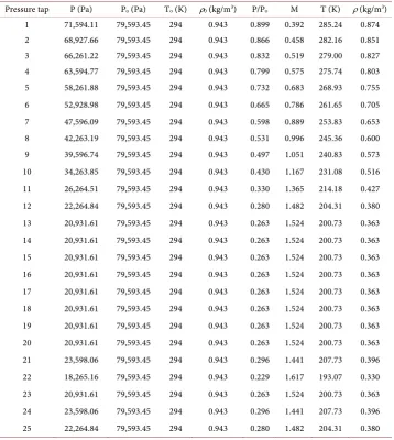
On the other hand, with the aim to know the flow behavior in the double-wedge airfoil, an experiment was realized at 1.6 Mach number and the static pressure data were regis-tered at this condition. The static pressure used to compute the Mach number, temper-ature and density in the wind tunnel test section. These results are showed in Table 1, for a stagnation pressure of 79,593 Pa. The oblique shock wave visualization on the double-wedge airfoil by means of the Schlieren method was carried out at the condi-tions showed in the Table 1. Figure 3 shows the flow visualization and the oblique shock angle on the double-wedge airfoil.
The Schlieren method consists in emitting a ray of light from the light source of 12 volts, this ray passes through a convex mirror and then by a slit, that strikes the concave mirror No. 1. After that this light ray passes through the Schlieren window of the su-personic wind tunnel, where is located the double wedge profile and it is reflected into the concave mirror No. 2. Therefore the light ray is projected on a plane mirror, which is located in front of the screen where resulting image is projected, Figure 3(b). This phenomenon is a technique for projecting optical images due to the air refractive index. Schlieren systems are used to visualize the flow away from the surface of an object.
3. Numerical Simulation
(a) (b)
Figure 3. Schlieren method and the oblique shock wave on the double-wedge airfoil at leading and tailing: (a) flow visualization; (b) oblique shock angles.
Table 1. Conditions of the test, in the supersonic wind tunnel.
Pressure tap P (Pa) Po (Pa) To (K) ρ0 (kg/m3) P/Po M T (K) ρ (kg/m3)
1 71,594.11 79,593.45 294 0.943 0.899 0.392 285.24 0.874 2 68,927.66 79,593.45 294 0.943 0.866 0.458 282.16 0.851 3 66,261.22 79,593.45 294 0.943 0.832 0.519 279.00 0.827 4 63,594.77 79,593.45 294 0.943 0.799 0.575 275.74 0.803 5 58,261.88 79,593.45 294 0.943 0.732 0.683 268.93 0.755 6 52,928.98 79,593.45 294 0.943 0.665 0.786 261.65 0.705 7 47,596.09 79,593.45 294 0.943 0.598 0.889 253.83 0.653 8 42,263.19 79,593.45 294 0.943 0.531 0.996 245.36 0.600 9 39,596.74 79,593.45 294 0.943 0.497 1.051 240.83 0.573 10 34,263.85 79,593.45 294 0.943 0.430 1.167 231.08 0.516 11 26,264.51 79,593.45 294 0.943 0.330 1.365 214.18 0.427 12 22,264.84 79,593.45 294 0.943 0.280 1.482 204.31 0.380 13 20,931.61 79,593.45 294 0.943 0.263 1.524 200.73 0.363 14 20,931.61 79,593.45 294 0.943 0.263 1.524 200.73 0.363 15 20,931.61 79,593.45 294 0.943 0.263 1.524 200.73 0.363 16 20,931.61 79,593.45 294 0.943 0.263 1.524 200.73 0.363 17 20,931.61 79,593.45 294 0.943 0.263 1.524 200.73 0.363 18 20,931.61 79,593.45 294 0.943 0.263 1.524 200.73 0.363 19 20,931.61 79,593.45 294 0.943 0.263 1.524 200.73 0.363 20 20,931.61 79,593.45 294 0.943 0.263 1.524 200.73 0.363 21 23,598.06 79,593.45 294 0.943 0.296 1.441 207.73 0.396 22 18,265.16 79,593.45 294 0.943 0.229 1.617 193.07 0.330 23 20,931.61 79,593.45 294 0.943 0.263 1.524 200.73 0.363 24 23,598.06 79,593.45 294 0.943 0.296 1.441 207.73 0.396 25 22,264.84 79,593.45 294 0.943 0.280 1.482 204.31 0.380
[image:4.595.196.555.292.693.2]density based, steady, 2D space planar, velocity formulation absolute and the special discretization is, gradient: Green-Gauss, cel. Based, flow: Second Order Upwind, mod-ified turbulent viscosity: First Order Upwind. Preliminary results of the study have re-ported in [11], in which the Spalart-Almaras turbulence model and a largest volume control for geometry were used.
3.1. The Standard k-Є Model
The standard k- model is a semi-empirical model based on transport model equa-tions for the turbulent kinetic energy (k) and its dissipation rate (). The transport model equation for k is derived from the exact equation, while the transport model eq-uation for is obtained by using physical reasoning and bears little resemblance to its mathematically exact counterpart. In the derivation of the k- model, it was assumed that the flow is fully turbulent.
3.2. Transport Equations for the Standard k-Є Model
The turbulent kinetic energy and its rate of dissipation are obtained from the following transport equations:
t
k b M
i k i
Dk k
G G Y
Dt x x
µ
ρ µ ρ
σ
∂ ∂
=∂ + ∂ + + − −
(1)
(
)
1 3
t
k b k
i k i
D
C G C G
Dt x x k
µ ρ µ σ ∂ ∂ = + + + ∂ ∂
(2)
2
2 C
k ρ
− (3)
In these Equations (1)-(3), GK represents the generation of turbulent kinetic energy
due to buoyancy, YM represents the contributions of the fluctuating dilation in
com-pressible turbulence to the overall dissipation rate, C1, C2, and C3, are constants, σk and σ are the turbulent Prandtl numbers for k and ϵ respectively.
3.3. Model Constants
The model constants, energy Prandtl is 0.85, wall Prandtl number is 0.85, C1, C2,
3
C, σk and σ are the empiric constants having the following default values:
1 1.44, 2 1.92, 0.99, k 1.0, 1.3
C = C = Cµ = σ = σ= (4)
The degree to which is affected by the buoyancy is determined by the constant
3
C, it is not specified, but it is instead calculated according to the following relation.
3 tan
v C
u =
(5)
3.4. Computational Model and Boundary Conditions
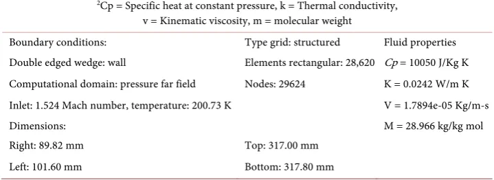
Figure 4 shows the computational model and Table 2 shows the boundary conditions. In particular, it describes the type grid, mesh and fluid properties that are used in the computational model.
4. Analysis and Results Comparison
Figure 5 shows the oblique shock waves in the leading edge and trailing edge double wedge airfoil at 1.6 Mach number. Also shows the compression zone, the ach number decreases to 1.4 due at change of flow direction, while expansion zone the flow is acce-lerating to reach a 1.6 Mach number. The Mach angle in oblique shock wave in the leading edge and trailing edge are 47˚ and 37˚, respectively.
[image:6.595.198.546.314.509.2] [image:6.595.194.554.574.705.2]With the aim to visualize the flow, the Schlieren method was used. Figure 3 shows the implementation, and the oblique shock angles, 46˚ and 36˚, for the oblique shock waves. The behavior of static pressure field on the double-wedge airfoil can be seen in Figure 6.
Figure 4. The computational model.
Table 2. Boundary conditions, type grid and fluid properties.
2Cp = Specific heat at constant pressure, k = Thermal conductivity,
v = Kinematic viscosity, m = molecular weight
Boundary conditions: Type grid: structured Fluid properties Double edged wedge: wall Elements rectangular: 28,620 Cp = 10050 J/Kg K Computational domain: pressure far field Nodes: 29624 K = 0.0242 W/m K Inlet: 1.524 Mach number, temperature: 200.73 K V = 1.7894e-05 Kg/m-s Dimensions: M = 28.966 kg/kg mol Right: 89.82 mm Top: 317.00 mm
Figure 5. The oblique shock waves in the leading edge and trailing edge double-wedge airfoil at 1.6 Mach number.
Figure 6. Static pressure field on the double-wedge airfoil.
Figure 7. Static temperature field on the double-wedge airfoil.
quently, at the middle part in the model, the flow changes direction entering in an ex-pansion zone where temperature decreases at 183 K for 1.7 Mach number.
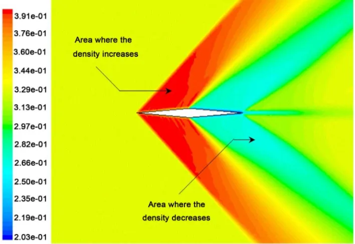
Figure 8 presents the density behavior at the double-wedge airfoil at 1.6 Mach with a density value of 0.328 Kg/m3 and in the compression zone the density is 0.402 Kg/m3.
After this zone the flow changes its direction in the middle part of the model entering in the expansion zone where it accelerates up to get 1.7 Mach and the density decreases to 0.298 Kg/m3. Flow changes its direction again producing the second oblique shock
wave in the trailing edge where the density increases to 0.331 Kg/m3.
Mach numbers comparison for the experimental and numerical simulation is showed in Figure 9. It is observed that Mach number behavior in both cases is the same from pressure tap 13 up to tap 20. The Mach number is numerically present a value larger than experimental value at the pressure taps 24 and 25 due to the boundary condition at the outlet from the computational model. For these values the difference in the maximum Mach numbers is about 2% respect to experimental values.
5. Conclusion
Figure 8. The density behavior at the double-wedge airfoil.
Figure 9. Comparison of Mach numbers obtained experimentally and numerically in supersonic flow.
Acknowledgements
The authors are grateful to SIP IPN for supporting part of this project through grant 20162113.
References
[1] Hsu, M.-H., Teng, W.-H. and Lai, C. (1998) Numerical Simulation of Supercritical Shock-wave in Channel Contraction. Computers and Fluids, 27, 347-365.
https://doi.org/10.1016/S0045-7930(97)00068-6
[2] Chen, S.X. (1992) Existence of Local Solution to Supersonic Flow past a Three-Dimensional Wing. Advances in Applied Mathematics, 13, 273-304.
https://doi.org/10.1016/0196-8858(92)90013-M
[3] Chen, G.-Q. and Feldman, M. (2005) Potential Theory for Shock Reflection by a Large- Angle Wedge. Proceedings of the National Academy of Sciences, 102, 15368-15372.
https://doi.org/10.1073/pnas.0505549102
[4] Schaeffer, D.G. (1976) Supersonic Flow past a Nearly Straight Wedge. Duke Mathematical Journal, 43, 637-670. https://doi.org/10.1215/S0012-7094-76-04351-9
[5] Li, D. (2004) Analysis on Linear Stability of Oblique Shock Waves in Steady Supersonic Flow. Journal of Differential Equations, 207, 195-225.
http://www.sciencedirect.com/science/article/pii/S0022039604003559185 https://doi.org/10.1016/j.jde.2004.08.021
[6] Abutabikh, M.I. (2015) Improving the Lift Characteristics of Supersonic Double Wedge Airfoil at Low Speed Using Passive-Active. Flow Controlling Methods, 33, 257-272. [7] Gupta, A. (2000) Supersonic Channel Airfoils for Reduced Drag. AIAA Journal, 38, 480-
486. https://doi.org/10.2514/3.14436
[8] Kolluru, R. and Gopal, V. (2012) Numerical Study of Navier-Stokes Equations in Super-sonic Flow over a Double Wedge Airfoil using Adaptive Grids. Proceedings of the 2012
COMSOL Conference, Bangalore, 1-6.
[9] Shameem, B., Ebna, M. and Bause, M. (2013) Numerical Simulation of Fluid Structure In-teraction (FSI) on a double wedge Airfoil based on Arbitrary Lagrangian-Eulerian Frame-works. The Workshop on Numerical Modelling of Grains/Fluid Flows, Lyon, November 2013.
[10] Magri, V. and Kalkhoran, I.M. (2013) Numerical Investigation of Oblique Shock Wave/ Vortex Interaction. Computers and Fluids, 86, 343-356.
https://doi.org/10.1016/j.compfluid.2013.06.018
[11] T.V.S.F. Garrido, J. and Tolentino, E. (2002) Experimental and Numerical Simulations of Oblique Shock Waves on Double Wedge Airfoil. The 10th International Symposium on Flow Visualization, Kyoto.
Submit or recommend next manuscript to SCIRP and we will provide best service for you:
Accepting pre-submission inquiries through Email, Facebook, LinkedIn, Twitter, etc. A wide selection of journals (inclusive of 9 subjects, more than 200 journals)
Providing 24-hour high-quality service User-friendly online submission system Fair and swift peer-review system
Efficient typesetting and proofreading procedure
Display of the result of downloads and visits, as well as the number of cited articles Maximum dissemination of your research work