University of Huddersfield Repository
Abid, Abdulbasit Z., Gdeisat, Munther A., Burton, David R., Lalor, Michael J., AbdulRahman,
Hussein S. and Lilley, Francis
Fringe pattern analysis using a onedimensional modified Morlet continuous wavelet transform
Original Citation
Abid, Abdulbasit Z., Gdeisat, Munther A., Burton, David R., Lalor, Michael J., AbdulRahman,
Hussein S. and Lilley, Francis (2008) Fringe pattern analysis using a onedimensional modified
Morlet continuous wavelet transform. In: Proceedings of SPIE: Optical and Digital Image
Processing. SPIE. ISBN 9780819471987
This version is available at http://eprints.hud.ac.uk/id/eprint/14957/
The University Repository is a digital collection of the research output of the
University, available on Open Access. Copyright and Moral Rights for the items
on this site are retained by the individual author and/or other copyright owners.
Users may access full items free of charge; copies of full text items generally
can be reproduced, displayed or performed and given to third parties in any
format or medium for personal research or study, educational or notforprofit
purposes without prior permission or charge, provided:
•
The authors, title and full bibliographic details is credited in any copy;
•
A hyperlink and/or URL is included for the original metadata page; and
•
The content is not changed in any way.
For more information, including our policy and submission procedure, please
contact the Repository Team at: [email protected].
Fringe pattern analysis using a one-dimensional modified Morlet
continuous wavelet transform
Abdulbasit Z. Abid
a, Munther A. Gdeisat*
a, David R. Burton
a, Michael J. Lalor
a, Hussein S.
Abdul-Rahman
a, Francis Lilley
aa
The General Engineering Research Institute (GERI), Liverpool John Moores University,
James Parsons Building Room 114, Byrom Street, Liverpool L3 3AF, United Kingdom
ABSTRACT
This paper proposes the use of a modified Morlet wavelet in order to demodulate fringe patterns in conjunction with the one-dimensional continuous wavelet transform (1D-CWT). Our investigations demonstrate that the modified Morlet wavelet produces better results compared to the conventional Morlet wavelet when used in fringe pattern analysis. This novel technique offers superior performance in analysing fringe patterns from objects that exhibit large height variations. This new technique has been used in conjunction with the direct maximum ridge extraction algorithm and an improvement in performance is observed. The algorithm has been tested using both computer-generated and real fringe patterns; and was found to be suitable for fringe pattern demodulation and robust in operation.
Keywords: Fringe analysis, phase retrieval, wavelets
1. INTRODUCTION
During the last decade, the wavelet transform (WT) has become a potential method of choice for use in the phase demodulation of fringe patterns. Fringe patterns tend to resemble non-stationary signals. The WT is an excellent tool for the processing of non-stationary signals due to its properties of being firstly a multi-resolution technique and secondly of offering good localisation in the time and frequency domains [1, 2]. In the literature, the one-dimensional continuous wavelet transform (1D-CWT) has been extensively used with the conventional Morlet wavelet in the phase demodulation of fringe patterns [3]. In this paper, a modified Morlet wavelet is adopted with the 1D-CWT. However, Wang et al.
proposed the same concept with the 2D-CWT [4]. Our proposed one-dimensional modified Morlet continuous wavelet shows that it behaves much better than the conventional Morlet wavelet in the case of large variations in phase across the fringe patterns.
In this paper, section 2 explains the 1D-CWT and the complex Morlet wavelet. In section 3, the direct maximum ridge extraction algorithm is described. The proposed modified Morlet wavelet is presented in section 4. The results of analysing computer-simulated and real fringe patterns using the conventional and the modified Morlet wavelets are discussed in section 5.
2. THE ONE-DIMENSIONAL CONTINUOUS WAVELET TRANSFORM
The wavelet transform is a suitable tool for the analysis of non-stationary signals and thus it has been developed as an alternative approach to the standard transforms currently available and traditionally used in fringe pattern analysis, such as the Fourier transform [5]. Moreover, it is worth mentioning that the wavelet transform has a multi-resolution property in the time and frequency domains, which overcomes the resolution problem inherent in other transforms.
The term wavelet means a small wave of limited duration and it can be either real or complex. However, two conditions must be satisfied with respect to any wavelet, namely: the wavelet must have an average value of zero and finite energy. Many different types of mother wavelets are available, but for the application of phase evaluation in fringe patterns the most suitable mother wavelet is probably the complex Morlet [5]. This is because it provides superior localisation in both the spatial and frequency domains.
*[email protected]; www.ljmu.ac.uk/geri
Optical and Digital Image Processing, edited by Peter Schelkens, Touradj Ebrahimi, Gabriel Cristóbal, Frédéric Truchetet, Proc. of SPIE Vol. 7000, 70000Q, (2008) · 0277-786X/08/$18 · doi: 10.1117/12.781677
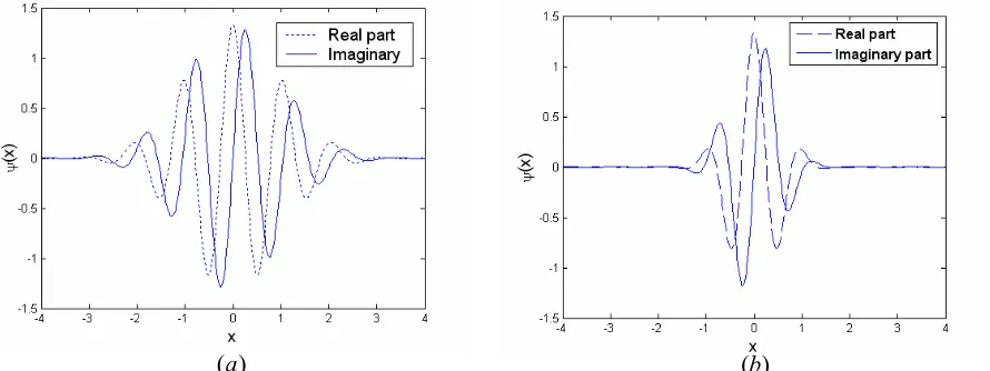
The conventional complex Morlet wavelet is a sine wave modulated by a Gaussian function [3], and is defined as
)
exp(
)
exp(
)
(
x
=
π
1/4icx
−
m
x
2ψ
(1)where c is a fixed spatial frequency, and chosen to be about 5 to 6 to satisfy the admissibility condition [5] and
x
is the index to pixels in the x direction. Fig. 1(a) shows the real part (dashed line) and the imaginary part (solid line) of the conventional Morlet wavelet where the m parameter is set to 0.5.However, the phase of a fringe pattern is extracted row by row when using the 1D-CWT and the process can be described as follows. The one-dimensional continuous wavelet transform of a row ƒ(x) of a fringe pattern is obtained by translation on the x axis by b (with y fixed) and dilation by s of the complex mother wavelet ψ(x) as given by
dx
s
b
x
x
f
s
b
s
W
⎟
⎠
⎞
⎜
⎝
⎛ −
=
∫
∞ ∞ − *)
(
1
)
,
(
ψ
(2)where * denotes complex conjugation and W(s,b) is the set of calculated CWT coefficients, which refers to the closeness of the signal to the wavelet at a particular scale. W(s,b) is a two dimensional complex array and hence the modulus and the phase arrays can be calculated by equations (3) and (4) respectively.
)
,
(
)
,
(
s
b
W
s
b
abs
=
(3)⎟⎟
⎠
⎞
⎜⎜
⎝
⎛
ℜ
ℑ
=
−)}
,
(
{
)}
,
(
{
tan
)
,
(
1b
s
W
b
s
W
b
s
ϕ
(4)Where ℜ{W(s,b)} and ℑ{W(s,b)} are the real and the imaginary parts of the CWT respectively. Once the row of the fringe pattern has been processed using the 1D-CWT, the phase of the row can be extracted by detecting the ridge of the WT from the modulus array. The next section explains the direct maximum algorithm that has been used in this work to extract the ridge of the CWT.
3. DIRECT MAXIMUM RIDGE EXTRACTION ALGORITHM FOR 1D-CWT
By definition, the ridge corresponds to the maximum of the CWT modulus and the modulus should have a maximum value when the complex Morlet wavelet frequency is very close to the frequency of the fringes [3]. In this paper, the direct maximum algorithm is employed to extract the ridge of the CWT. Other methods can be used to extract the ridge such as the cost function algorithm [7, 8].
The direct maximum ridge extraction algorithm was proposed by Carmona et al. [6]. In this approach, the ridge is extracted from the amplitude of the CWT as follows. The maximum value of each column in the modulus array is determined and then the corresponding phase is chosen from the phase array [3]. This process is repeated for all the rows of the fringe pattern and the final result is a wrapped phase map which needs to be subsequently unwrapped.
4. THE MODIFIED MORLET WAVELET
In the proposed algorithm, the complex Morlet wavelet is chosen and modified in order to cope with the large variations in phase within the fringe patterns. The modified Morlet wavelet is expressed by equation (1) with the parameter m set to 2. Fig. 1(b) shows the real part (dashed line) and the imaginary part (solid line) of the modified complex Morlet wavelet. It has been demonstrated by previous experimental investigation using the 2D-CWT in [4], that using a modified complex Morlet wavelet with the m parameter set to a value of 2 gives superior results over traditional techniques which use a value of m = 0.5. The modified complex Morlet wavelet performs better than the conventional complex Morlet
U.S
5*
-U.S
—l
-l S
-4 -3 -2
x
2 3 4 U.S
5*
-U.S
—l
-l S
-4 -3 -2
x
2 3 4
wavelet. This can be interpreted as follows. In CWT, the signal phase is assumed to be linear in the area covered by the Gaussian windows. If the fringe frequency varies dramatically, broad window size will generate error. Moreover, the window size is varying according to the signal frequency. It performs very poorly when the signal frequency is low, as it will automatically adjust the window size to be very large. This will generate errors because of the conflict with linear phase assumption. However, in this work, the superiority of using a value of m=2.0, as opposed to values of to m=0.5, 1 and 1.5, has been demonstrated by the processing of a number of different experimental interferograms using the 1D-CWT.
5. SIMULATION AND EXPERIMENTAL RESULTS
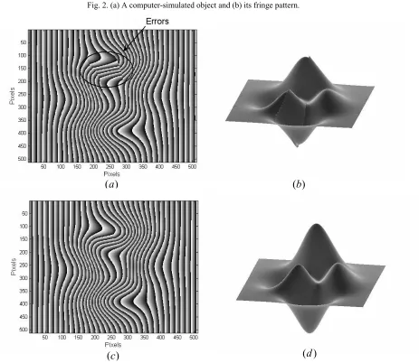
For testing purposes, 512×512 pixels images of both simulated and real objects are used in this work. A computer-generated object shown in Fig. 2(a) phase modulates fringes. The resulting fringe pattern is shown in Fig. 2(b) and it has been used to test the proposed algorithm. The computer-generated object is expressed by
)
)
1
(
exp(
3
1
)
exp(
)
5
(
10
)
)
1
(
exp(
)
1
(
3
)
,
(
x
y
=
−
x
2−
x
2−
y
+
2−
x
−
x
3−
y
5−
x
2−
y
2−
−
x
+
2−
y
2φ
(5)and its fringe pattern is given by;
))
,
(
7
.
3
2
cos(
)
,
(
x
y
f
x
x
y
I
=
π
o+
φ
(6)where ƒo is the spatial carrier frequency, which implies that the phase across the fringe pattern is monotonically
increasing and it is set to 1/16 and 3.7 is the sensitivity of the simulated fringe pattern projection system.
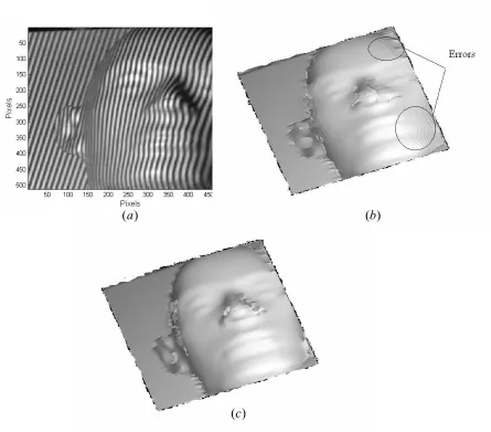
[image:4.612.69.514.167.334.2]As mentioned in section 2, in using the 1D-CWT, the phase of the simulated or the real fringe pattern is extracted on a row by row basis. The direct maximum ridge extraction algorithms is employed with the conventional complex Morlet wavelet and secondly with the modified Morlet wavelet. The scale values in these tests have been set to {1,2, …64}. Hence with the simulated object, two wrapped phase maps result, as shown in Figs. 3(a) and (c), and they must then be unwrapped, as shown in Figs. 3(b) and (d). The previous procedures have been repeated for a real fringe pattern, namely the mannequin’s face object shown in Fig. 4(a). Again two unwrapped phase maps result, as shown in Figs. 4(b) & (c). The results of testing both the simulated and the real fringe patterns show that the modified complex Morlet wavelet behaves much better than the conventional one. In addition, some areas in the wrapped phase map shown in Fig. 3(a); and also visible in the unwrapped phase maps in Figs. 3(b) & 4(b), exhibit errors when using the conventional Morlet wavelet. These errors are eliminated when the modified Morlet wavelet is adopted, as shown in Figs 3(c), (d) and Fig. 4(c). The proposed algorithm has succeeded in accurately demodulating both the simulated and the real objects, whilst the conventional Morlet wavelet has failed to do so.
Fig. 1. The complex Morlet mother wavelet (a) the conventional and (b) the modified.
)
(a (b)
200
250
0-355
350
400
450
50 100 ISO 200 260 300 360 400 460 600 Pixels
255
250
0-355
350
400
450
Errors
50 lOS ISO 255 265 355 365 455 465 655 Pixels
200
250
0-355
350
400
450
50 100 ISO 200 260 300 360 400 460 600 Pixels
Fig. 2. (a) A computer-simulated object and (b) its fringe pattern.
)
(
a
(
b
)
)
(
a
(
b
)
)
(
c
(
d
)
Fig. 3. (a) & (c) The wrapped phase of the simulated object using the conventional complex and modified Morlet wavelets respectively, (b) & (d) the unwrapped phase of the simulated object using the conventional complex and modified Morlet wavelets respectively.
[image:5.612.51.511.68.251.2] [image:5.612.66.529.260.662.2]255
265
0-355
365
•,,,1ifj7,7//7qj111
/ ('I,rhI/Ii1i/n
SO ISO ISO 200 260 300 360 PixelsEnors
H
[image:6.612.79.524.63.454.2]Finally in terms of performance, the proposed 1D-CWT algorithm outperforms one of the most popular fringe pattern analysis techniques which is that of Fourier Transform Fringe Analysis (FTFA) [9]. In this paragraph, a brief comparison between the 1D-CWT technique in two forms, employing both the conventional and the modified Morlet wavelet, and the Fourier transform method will be carried out. The fringe pattern shown in Fig. 2(b) was demodulated using both the 1D-CWT and FTFA methods. The mathematical difference between the unwrapped phase map and the original object shown in Fig. 2(a) is considered to be the error. For all cases, the root mean square error is calculated for the full image. Table 1 shows the results which demonstrate that the 1D-CWT employing the modified Morlet wavelet is more accurate than both the FTFA method and the 1D-CWT employing the conventional Morlet wavelet.
Table 1. Root mean square errors for 1D-CWT and FTFA techniques.
Fringe analysis technique Root mean square error (rad)
Conventional Morlet (m=0.5) 0.0400 Modified Morlet (m=2.0) 0.0021
Fourier Transform 0.0519
)
(
a
(
b
)
)
(
c
Fig. 4. (a) A fringe pattern of a mannequin’s face, (b) & (c) the unwrapped phase of the real object using the conventional and the modified complex Morlet wavelets respectively.
[image:6.612.140.466.636.689.2]All the algorithms in this paper were programmed in the C language and executed on a Pentium 4 computer with a 3.60 GHz clock speed and 2 GByte RAM memory. The execution time required to process the fringe pattern shown in Fig. 2(b) using the modified and conventional Morlet 1D-CWT algorithms on this hardware platform was approximately 21 seconds. Moreover, the fast Fourier transform algorithm has been used in the implementation of the 1D-CWT techniques to get faster calculation results. The unwrapped phase maps, both in simulation and experimental work, were produced using Herráez’s algorithm [10]. The C code for Herráez’s phase unwrapping algorithm can be freely downloaded from our website [11].
6. CONCLUSION
In this paper, a modified complex Morlet has been employed with the 1D-CWT. The direct maximum ridge extraction algorithm has been employed in order to extract the phase information from a fringe pattern. The performance of the proposed modified wavelet has been evaluated using both computer-generated and real fringe patterns. The resulting unwrapped phase maps from the proposed algorithm are confirmed to be smooth and accurate. In conclusion, the presented algorithm is shown to be reliable and very effective in demodulating fringe patterns.
REFERENCES
[1] Zhong, J. and Weng, J., “Spatial Carrier-Fringe Pattern Analysis by Means of Wavelet Transform: Wavelet
Transform Profilometry,” Appl. Opt. 43(26), 4993-498 (2004).
[2] Zeng, H. and Zhong, J., “Local frequency and phase analysis of interferogram, ”Proc. of SPIE 6150, 61503S
(2006).
[3] Gdeisat, M. A., Burton, D. R. and Lalor, M. J., “Spatial carrier fringe pattern demodulation by use of a
two-dimensional continuous wavelet transform,” Appl. Opt. 45(34), 8722-8732 (2006).
[4] Wang, Z. and Ma, H., “Advanced continuous wavelet transform algorithm for digital interferogram analysis and
processing,” Opt. Eng. 45(4), 045601 (2006).
[5] Dursun, A., Ozder, S. and Ecevit, F. N., “Continuous wavelet transform analysis of projected fringe patterns,”
Meas. Sci. and Tech. 15(9), 1768-1772 (2004).
[6] Carmona, R. A., Hwang, W. L. and Torrésani, B., “Characterization of signals by the ridges of their wavelet
transforms,” IEEE Trans. on sig. proc. 45(10), 2586-2590 (1997).
[7] Liu, H., Cartwright, A. N. and Basaran, C., “Moiré Interferogram Phase Extraction: A Ridge Detection
Algorithm for Continuous Wavelet Transforms,” Appl. Opt. 43(4), 850-857 (2004).
[8] Abid, A. Z., Gdeisat, M. A., Burton, D. R., Lalor, M. J. and Lilley, F., “Spatial fringe pattern analysis using the
two-dimensional continuous wavelet transform employing a cost function,” Appl. Opt. 46(24), 6120-6126 (2007).
[9] Lilley, F., Lalor, M. J. and Burton, D. R., "Robust Fringe Analysis System for Human Body Shape
Measurement", Opt. Eng, 39(1), 187 – 195 (2000).
[10] Herráez, M. A., Burton, D. R., Lalor, M. J. and Gdeisat, M. A., “Robust, Fast, and Effective Two-Dimensional
Automatic Phase Unwrapping Algorithm Based on Image Decomposition,” Appl. Opt. 41(35), 7437-7444 (2002).
[11] M. A. Gdeisat, http://www.ljmu.ac.uk/GERI/90202.htm.