Copyright © 2014 IJECCE, All right reserved
Power Quality Enhancement use DSTATCOM Based on
Sinusoidal Pulse Width Modulation
Pawan Jawlkar
Electrical Engineering Department, Gyanganga College of Technology, Jabalpur India
Email: [email protected]
Mrs. Ritu Sharma
Electrical Engineering Department, Gyanganga College of Technology, Jabalpur India
Email:[email protected]
Abstract–This paper investigates the effects Distribution STATCOM (DSTATCOM)[1] for power quality problems, like voltage sag and swell based on Sinusoidal Pulse Width Modulation (SPWM)[4] technique. A three-phase four-wire DSTATCOM (distribution static compensator) based on three-leg VSC (voltage source converter) and a star/delta transformer is proposed for power quality improvement. A harmonic current, reactive power and balances the load. Three single phase transformers are connected as star/delta transformer for interfacing to a three phase four-wire power distribution system and the required rating of the VSC [2] is reduced. However, a 4-leg VSC (voltage source converter[5]) based DSTATCOM (Distribution Static Compensator) is used for the load compensation and neutral current compensation in 3-phase 4-wire distribution system Power quality is an occurrence manifested as a nonstandard voltage, current or frequency that results in a failure of end use equipments. The major problems dealt here is the voltage sag and swell. To solve this problem, custom power devices are used. One of those devices is the Distribution STATCOM (D-STATCOM), which is the most efficient and effective modern custom power device used in power distribution networks. D-STATCOM injects a current in to the system to correct the voltage sag and swell. The control of the Voltage Source Converter (VSC) is done with the help of SPWM. The proposed D-STATCOM [11] is modelled and simulated using MATLAB/SIMULINK software [13].
Keywords – Distribution STATCOM (D-STATCOM),
MATLAB/ SIMULINK, Power Quality Problems, Sinusoidal Pulse Width Modulation (SPWM), Voltage Sag and Swell, Voltage Source Converter (VSC).
I. I
NTRODUCTIONModern industrial devices are mostly based on the electronic devices such as programmable logic controllers and electronic drives. The electronic devices are very sensitive to disturbances and become less tolerant to power quality problems such as voltage sags [3], swells and harmonics. Voltage dips are considered to be one of the most severe disturbances to the industrial equipments. Voltage support at a load can be achieved by reactive power injection at the load point of common coupling. D-STATCOM [6] injects a current into the system to correct the voltage sag and swell [2]. These power quality devices are power electronic converters connected in parallel or series with the lines and the operation is controlled by a digital controllers. The modelling of these complex systems that contains both power circuits and control systems can be done different bases. One of those power electronic solutions to the voltage regulation is the use of a Distribution STATCOM [10] (STATCOM).
D-STATCOM is a class of custom power devices for providing reliable distribution power quality. They employ a shunt of voltage boost technology using solid state switches for compensating voltage sags and swells. The D-STATCOM applications are mainly for sensitive loads that may be drastically affected by fluctuations in the system voltage
II. P
OWERQ
UALITYP
ROBLEMSThe power disturbances occur on all electrical systems,[12] the sensitivity of today's sophisticated electronic devices make them more susceptible to the quality of power supply. For some sensitive devices, a momentary disturbance can cause scrambled data, interrupted communications, a frozen mouse, system crashes and equipment failure etc. A power voltage spike can damage valuable components. Power quality problems [10] encompass a wide range of disturbances such as voltage sags, swells, flickers, harmonic distortion, impulse transients, and interruptions.
Causes of Voltage Sags and swells
Rural location remote from power source
Unbalanced load on a three phase system
Switching of heavy loads
Long distance from a distribution transformer with
Interposed loads
Unreliable grid systems
Equipments not suitable for local supply
Copyright © 2014 IJECCE, All right reserved major role in improving the inherent Supply quality; some
of the effective and economic measures can be identified as following [12]:
1) Lightning and Surge Arrester: Arrester is designed for lightning protection of transformers, but is not limited to sufficient voltage limiting for protecting sensitive electronic control circuits from voltage surges.
2) Thyristor Based Static Switch: The static switch is a versatile device for switching a new element in to the circuit when the voltage support is needed. It has a dynamic response time of about one cycle. To correct quickly for voltage spikes, sags or interruptions, the static switch can used to switch one or more devises such as capacitor, filter, alternate power line, energy storage systems etc. The static switch can be used in The alternate power line applications.
3) Energy Storage Systems: Storage system can be used to protect sensitive protection equipment from shutdowns caused by voltage sags or momentary interruptions. These are usually dc storage systems such as UPS, batteries, superconducting magnet energy storage (SMES), storage capacitors or even fly wheels driving dc generators. The output of these devices can be supplied to the system through an inverter on a momentary Basis by a fast acting electronic switch. Enough energy is fed to the system to compensate for the energy that would be lost by the voltage sag or interruption
III. D
ISTRIBUTIONSTATCOM
(D-STATCOM)
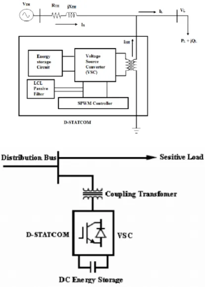
A D-SATTCOM which is schematically depicted in Fig. 2 consists of a two level voltage source converter (VSC), a dc energy storage device, a coupling transformer connected in shunt to the distribution network through a coupling transformer [6], [7]. Such configuration allows the device to absorb or generate controllable active and reactive power. The D-STATCOM [3] has been utilized mainly for regulation of voltage, correction of power factor and elimination of current harmonics. Such a device is employed to provide continuous voltage regulation using an indirectly controlled converter [7]. In this paper, the D-STATCOM is used to regulate the voltage at the point of connection. The control is based on sinusoidal PWM and only requires the measurement of the rms voltage at the load point.
IV. D
ISTRIBUTEDS
TATICC
OMPENSATOR(DSTATCOM)
The Distribution Static Compensator (DSTATCOM) is a voltage source inverter based static compensator (Similar in many respects to the DVR)[8] that is used for the correction of bus voltage sags. Connection (shunt) to the distribution network is via a standard power distribution transformer. The DSTATCOM is capable of Generating continuously variable inductive or capacitive shunt compensation at a level up its maximum MVA Rating. The DSTATCOM continuously checks the line waveform with respect to a reference ac signal, and therefore, it can
provide the correct amount of leading or lagging reactive current compensation to reduce the Amount of voltage fluctuations. The major components of a DSTATCOM are shown in Fig. 1. It consists of a dc capacitor, one or more inverter modules, an ac filter, a transformer to match the inverter output to the line voltage, and a PWM control strategy. In this DSTATCOM implementation, a voltage-source inverter converts a dc voltage into a three-phase ac voltage that is synchronized with, and connected to, the ac line through a small tie reactor and capacitor (ac filter)[9]. The control is based on sinusoidal PWM [4] and only requires the measurement of the rms[9] voltage at the load point
Fig.1. Schematic diagram of a D-STATCOM It may be mentioned that the effectiveness of the D-STATCOM in correcting voltage sag depends on the value of ZTH or fault level of the load bus. When the shunt injected current ISH is kept in quadrature with VL, the desired voltage correction can be achieved without injecting any active power into the system. On the other hand, when the value of ISH is minimized, the same voltage correction can be achieved with minimum apparent power injection into the system.
DSTATCOM components: DSTATCOM involves mainly three parts
A. IGBT or GTO based dc-to-ac inverters:
These inverters are used which create an output voltage wave that’s controlled in magnitude and phase angle to produce either leading or lagging reactive current, depending on the Compensation required.
B. L-C Filter
:Copyright © 2014 IJECCE, All right reserved in accordance with the type of the system and the
harmonics present at the output of the inverter.
C. Control Block:
Control block is used which switch Pure Wave DSTATCOM modules as required. They can Control external devices such as mechanically switched capacitor banks too. These control blocks are designed Based on the various control theories and algorithms like instantaneous PQ theory, synchronous frame theory Etc.
V. V
OLTAGES
OURCEC
ONVERTERS(VSC)
A voltage-source converter is a power electronic device, which can generate a sinusoidal voltage with any required magnitude, frequency and phase angle. Voltage source converters are widely used in adjustable-speed drives, but can also be used to mitigate voltage dips. The VSC [5] is used to either completely replace the voltage or to inject the „missing voltage‟. The „missing voltage is the difference between the nominal voltage and the actual. The converter is normally based on some kind of energy storage, which will supply the converter with a DC voltage. The solid-state electronics in the converter is then switched to get the desired output voltage. Normally the VSC [6] is not only used for voltage dip mitigation, but also for other power quality issues, e.g. flicker and harmonics. A special gate unit and voltage divider across each IGBT maintain an even voltage distribution across the series connected IGBTs. The gate unit not only maintains proper voltage sharing within the valve during normal switching conditions but also during system disturbances and fault conditions. A reliable short circuit failure mode exists for individual IGBTs within each valve position.[9] Depending on the converter rating, series-connected IGBT valves are arranged in either a three-phase two-level or three-level bridge. In three-level converters, IGBT valves may also be used in place of diodes for neutral point clamping. Each IGBT position is individually controlled and monitored via fibber optics and equipped with integrated ant parallel, free-wheeling diodes. Each IGBT has a rated voltage of 2.5 kV with rated currents up to 1500 A. Each VSC station is built up with modular valve housings which are constructed to shield electromagnetic interference (EMI). The valves are cooled with circulating water and water to air heat exchangers. PWM switching frequencies for the VSC typically range between 1-2 kHz depending on the converter topology, system frequency and specific application.
VI. S
INUSOIDALPWM B
ASEDC
ONTROLThe aim of the control scheme is to maintain constant voltage magnitude at the point where a sensitive load is connected, under system disturbance. The control system only measures the rms voltage at the load point i.e., no reactive power measurements are required [9]. The VSC switching strategy is based on sinusoidal PWM technique which offers simplicity and good response. The PI controller process identifies the error signal and Generates
the required angle () to drive the error to zero, i.e., the load rms voltage is brought back to the reference voltage. In the PWM generator, the sinusoidal signal vcontrolis compared against a triangular signal (carrier) in order to generate the switching signals for the VSC valves [3], [9]. The main parameters of the sinusoidal PWM scheme are the amplitude modulation index ma of signal vcontrol and the frequency modulation index Mf of the triangular signal. The amplitude index Mais kept fixed at 1 pu.
Ma=vcontrol/vtrl (1)
Where vcontrol is the Peak amplitude of the signal.
vtrl is the peak amplitude of the Triangular signal. In order to obtain the highest fundamental voltage component at the controller output [10], the switching frequency is set at 450 Hz. The frequency of modulation index is given by, In this paper, balanced network and operating conditions are assumed. The modulation angle () is applied to the PWM generator in phase A. The angle for phases B and C are shifted by 240° and 120°, respectively [9]
VII. M
ODELING ANDS
IMULATIONThe aim of the control scheme is to maintain constant voltage magnitude at the point where a sensitive load is connected, under system disturbance. The control system only measures the rms voltage at the load point i.e., no reactive power[12] measurements are required. The VSC switching strategy is based on sinusoidal PWM [4] technique which offers simplicity and good response
Fig. 2 shows the test system used to carry out the various D-STATCOM simulations presented in this section. The test system composes a 230 kV, 50 Hz generation system. A varying load is connected to the 11 kV, secondary side of the transformer. A two-level D-STATCOM is connected to the 11 kV tertiary winding to provide instantaneous voltage support at the load point.
Copyright © 2014 IJECCE, All right reserved
VIII. R
ESULTSFig.3. Output voltage D-STATCOM
Fig.4. Outpout of Voltage Source Converter (VSC)
Fig.5. Output of Sinusoidal Pulse Width Modulation (SPWM)
Fig.6. Output of Sinusoidal Pulse Width Modulation (SPWM)
Fig.7. Output of 3-phase line
IX. ACKNOWLEDGMENT
I would like to thank (Mrs) Ritu sharma for technical support and helpful discussions about Matlab software programming
X. C
ONCLUSIONCopyright © 2014 IJECCE, All right reserved
S
COPE OFF
UTUREW
ORKFurther investigation of the D-STATCOM applications the newly development of the semiconductor devices and the rising demands in utility application provide a lot of opportunities of power flow control. With the promotion and development of smart grid and renewable energy application in the power system, the D-STATCOM applications will extend to different areas, from the high voltage transmission system to the residential distribution system. Further improvement of D-STATCOM power stage design Modular converter topology, ETO semiconductor device enable the low cost, high reliability and transformer less connection of D-STATCOM in transmission system application. With the new proposal of the D-STATCOM applications, the power stage design with different voltage/current rating in different application areas should be paid more attentions.
R
EFERENCES[1] MITIGATION OF POWER QUALITY PROBLEMS BY USING D-STATCOMISSN (Online): 2347-2812, Volume-1, Issue -3, 2013
[2] DQ based Control of DSTATCOM for Power Quality ImprovementVSRD-IJEECE, Vol. 2 (5), 2012, 207-227 [3] Comparison of Three leg and Four Leg VSC DSTATCOM for
Power Quality Assessment IOSR Journal of Electrical and Electronics Engineering (IOSR-JEEE) e-ISSN: 2278-1676, p-ISSN: 2320-3331, Volume 6, Issue 5 (Jul.- Aug. 2013), PP 43-49 [4] Modelling and Simulation of a Distribution STATCOM (D-STATCOM) for Power Quality Problems-Voltage Sag and Swell Based on Sinusoidal Pulse Width Modulation (SPWM) IEEE-International Conference On Advances In Engineering, Science And Management (ICAESM -2012) March 30, 31,2012 436 [5] O. Anaya-Lara, E. Acha, "Modeling and analysis of custom
power systems by PSCAD/EMTDC," IEEE Trans. Power Delivery, vol. 17, no . I, pp. 266-272, January 2002
[6] Noramin Ismail, Wan Norainin Wan Abdullah, "Enhancement of Power Quality in Distribution System Using D-STATCOM, the 4th International Power Engineering and Optimization Conference (PEOCO2010), Shah Alam, Selangor, MALAYSIA. 23-24 June 2010.
[7] Mohit Bajaj, Vinay Kumar Dwivedi, Ankit Kumar, Anurag Bansal, "Design and simulation of DSTATCOM for power quality Enhancement in distribution Networks under various Fault Condition," International Journal of Emerging Technology and Advanced Engineering, Volume 3, Issue 4, pp 620-626, April 2013
[8] G. Venkataramana, and BJohnson, "A pulse width modulated power line conditioner for sensitive load centers," IEEE Trans. Power Delivery,vol. 12, pp. 844-849, Apr. 1997.
[9] Rosli omar, Nasrudin abd rahim and Mazizan sulaiman "Modeling and simulation for voltage sags/swells mitigation using dynamic voltage restorer (DVR), " journal of theoretical and applied information technology, pp 464-470.
[10] Bhattacharya Sourabh, "Applications of DSTATCOM Using MATLAB/Simulation in Power System," Research Journal of Recent Sciences, Vol. 1(ISC-2011), pp 430-433 (2012). [11] Rodda Shobha Rani, B. Jyothi, "VSC Based DSTATCOM &
Pulse-width modulation for Power Quality Improvement," International Journal of Engineering Trends and Technology-Vol. 2, pp 38-41, 2011.
[12] M. Mohammadi, M. Akbari Nasab, "Voltage Sag Mitigation with D-STATCOM In Distribution Systems," Australian Journal of Basic and Applied Sciences, 5(5), pp 201-207, 2011 [13] I. Papic, “Power quality improvement using distribution static
compensator with energy storage system,” inProc. 9th Int. Conf. Harmon. Quality Power, 2000, pp. 916–920.