1
EXPERIMENTAL AND 3D-CFD STUDY ON OPTIMIZATION OF
CONTROL VALVE DIAMETER FOR A CONVERGENT VORTEX TUBE
Seyed Ehsan Rafiee
*, M. M. Sadeghiazad
Department of Mechanical Engineering, Urmia University of Technology, Urmia, Iran
A
BSTRACTThe aim of this investigation is study on separation phenomenon inside a special vortex tube affected by structural and physical factors including; throttle diameter, nozzle number and injection pressure as well as the parametric optimization based on separation efficiency using experimental and 3D-CFD methods. The results show that convergent VT with Dth=5.5mm provides 30.01% and 20.04% higher cooling and heating effectiveness compared to basic model. As another result, the higher injection pressure, the higher cooling effectiveness. The cooling effectiveness improves (16.86%) with increase in slot number up to N=4, then decreases. The maximum disagreement between experimental and predicted values is 6.25%.
Keywords: Control valve diameter; Nozzle number; Separation process; Convergent vortex tube; Injection pressure.
1.
INTRODUCTION
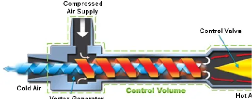
The vortex tube (VT) cyclone, also called separator in respect of the inventors to its invention and development (Ranque, 1933; Hilsch, 1947), is a useful and simple device with simplified structure but very wide usages. When a pressured gas (sometimes liquid such as hydrocarbon mixtures) is injected through the slots into the chamber of the VT cyclone separator, the temperature of the escaping flow at the central exhaust near the vortex chamber or slots area is lower than the flow incoming from the storage tank, at the same time, the temperature of the flow exiting from the circumferential exhaust at the other side of the cyclone separator tube is higher than the inlet flow.
Figure 1 describes a schematic representation of a counter-flow VT cyclone separator by air flow division within the main tube. The structure of the VT cyclone separator system can be divided into a number of components such as; a cold end orifice, a vortex-chamber, a number of nozzle slots, a main or hot tube and a control valve. The gas or fluid is pressured by a compressor and is stored in the storage tank. This pressured gas has been transported through the pipes and has been injected into the chamber via the nozzle slots. The tangential injection of pressured gas creates the strong rotating layers of gas inside the cyclone separator.
Fig. 1 Schematic diagram of a VT air separator with flow directions
* Corresponding author. Email: [email protected]
The gas has been injected tangentially via the nozzle slots and rotates around the central axis of the main tube, so the gas will be expanded and cooled. After the occurrence of the phenomenon of the flow separation inside the main tube, the input gas through the nozzle slots is divided into two streams (hot and cold) with large temperature differences. The first output is known as "cold exhaust" and is located close the nozzle slots. The hot exhaust is located on the other side of the main tube and this output is covered by a control valve which controls the rate of the hot flow. Opening the mentioned valve leads to increase in the flow rate at the hot exhaust, consequently, the cold air flow rate is reduced. It should be said that the VT cyclone separator performance has been managed with motion of the control valve.
Several scientific works have been done to develop the VT cyclone separator structure and efficiency. Here, we look at a brief review of some of these researches. Dutta et al (2011) tried to apply a CFD model for analyzing the fluid flow inside the main tube using the NIST real gas model. The ability to predict for several numerical models (the k–ɛ, k–ω and SST k–ω) was examined by Baghdad et al (2011). The effect of the main tube bending on the VT cyclone separator efficiency is studied by Valipour et al. (2011), Bovand et al. (2014a and 2014b) and Rafiee et al. (2016). Dincer et al. (2011) tested the VT cyclone separator in three different sorts (the conventional VT, threefold cascade type VT and six cascade type RHVT) under different pressure injections. Some structural parameters (the length of straight main tube, the cold and hot exhausts, the nozzle area ratio and the inlet slots) have been optimized by Im et al. (2012). Han et al. (2013) and Rafiee and Sadeghiazad (2016a) examined the effects of applying different types of inlet gases (R32, R728, R134a, R744, R161, R22, NO2, CO2, N2, O2 and air) on the heating and the cooling performance of a VT cooling system based on pressure analysis. Also, the effect of this operating parameter (different working gases) was numerically studied by Thakare and Parekh (2015). Mohammadi et al. (2013) tested a cooling VT cyclone separator system to optimize the
Frontiers in Heat and Mass Transfer
2 number and the diameter of the nozzles, the cold mass ratio and the intake pressure. Some researchers (Rafiee and Sadeghiazad, 2014a; Shamsoddini and Hossein Nezhad, 2010) focused on the effect of nozzle numbers and proved that the straight VT cyclone separator with the greater nozzle numbers has higher cooling power. A new type of nozzles were tested and optimized by Rafiee and Rahimi (2013) as the convergent nozzles. Their work showed that if the velocity of the gas entering the chamber increases (To a certain extent), the efficiency of the straight VT cyclone separator can be improved. The separated flow hysteresis phenomenon in the process of the streamlining the gas-turbine engines axial compressor is analyzed by Kulyk et al. (2012). The accuracy of different turbulence models in prediction of separation phenomenon has been analyzed by Rafiee and Sadeghiazad (2016b).In order to increase the energy separation rate and the thermal efficiency, and optimize the dimensions of the straight VT cyclone separator system, thereby decreasing the operating costs, the geometrical optimization techniques are usually applied. The length of hot tube has been optimized in a numerical work by Rafiee and Sadeghiazad (2016c). Pourmahmoud et al. (2014) investigated the effect of inlet temperature on the vortex tube performance.
Various tools are successfully used to optimize the structural parameters of the straight VT cyclone separator such as the exergy analysis (Saidi and Allaf Yazdi, 1999; Ouadha et al. 2013; Rafiee and Sadeghiazad, 2014b). Secchiaroli et al. (2009) designed a numerical investigation to analyze the internal flow in a straight VT cyclone separator which is used in a jet impingement system. Some numerical methods like the Taguchi (Murat et al. 2009), the Neural networks (Korkmaz, 2012) and the Rule-Based Mamdani-Type Fuzzy (RBMTF) modeling technique (Berber et al. 2013) recently have been used to optimize the operating conditions of the straight VT cyclone separator. Saidi and Valipour (2003) classified the effective parameters on the thermal performance of the straight VT cyclone separator into two categories namely; thermo-physical and structural ones. The influence of the geometrical parameters of the nozzle intakes such as the internal diameters has been experimentally investigated by Aydin and Baki (2006). A special type of VT is the divergent VT which in some small angles can have the better performance than the straight ones (Chang et al. 2011 and Rahimi et al. 2013). Dincer et al. (2008) and Agrawal et al. (2014) have accomplished some complete experimental works on the straight VT cyclone separator with various length to diameter ratios (L/D). The secondary circulation inside the straight VT cyclone separator is explained and described by Ahlborn and Gordon (2000). There are many benefits of working with the CFD numerical models. One of these advantages is that the CFD models present a clear and detailed description regarding the thermal distribution and the velocity field inside the straight VT cyclone separator (Akhesmeh et al. 2008; Rafiee and Rahimi, 2014; Aljuwayhel et al. 2005 and Skye et al. 2006). Two detailed reviews (Subudhi and Sen, 2015; Thakare et al. 2015) have been presented related to VT cyclone separator contents. The convergent angle and the cold orifice diameter of convergent vortex tube have been optimized (numerically and experimentally) by Rafiee et al. (2015).
Piralishvili and Polyaev (1996) and Alekhin et al. (2015) introduced a new type of the VT cyclone separator as double-circuit VTs. In this kind of VT cyclone separator an additional inlet is added on the hot throttle valve. Kandil and Abdelghany (2015) assessed the effect of some geometrical parameters such as the length to tube diameter ratio on the straight VT cyclone separator performance. Liu and his co-author (2014) proposed a three-dimensional model applied for predicting and calculating the temperature and velocity distributions to describe the energy and the gas separation phenomenon inside the straight VT cyclone separator.
Pourmahmoud et al. (2012) reported that the cold temperature difference can be improved using the helical nozzles. Khazaei et al. (2012) found that the size of the hot exhaust do not affect the thermal efficiency of the straight VT cyclone separator. Li et al. (2015) showed that the increase of the cold flow fraction (or the decrease of the pressure
at injectors) moves the stagnation point to the cold end. Gutak (2015) utilized a straight VT cyclone separator with high pressure natural gas stream. He found that the Joule Thomson effect has an important effect on the energy distribution process. Mohammadi and Farhadi (2014), in a valuable work, analyzed the separation process and the gas fractions inside a straight VT cyclone separator for a hydrocarbon mixture. The effect of conical valve angle has been analyzed (for straight vortex tubes) by Rafiee and Sadeghiazad (2014c). Khait et al. (2014) employed the RSM turbulence model to introduce a comprehensive CFD model for predicting the flow distribution inside the straight VT cyclone separator. The annular straight VT cyclone separator (The hot flow is redirected on the hot tube) was introduced by Sadi and Farzaneh-Gord (2014). Bej and Sinhamahapatra (2014) worked on the hot cascade type straight VT cyclone separator. In this kind of straight VT cyclone separator the hot gas flow exiting the first VT cycle is utilized as the inlet of the second VT cycle. The concept of nozzle aspect ratio and its effect on the separation phenomenon are studied in an experimental work by Avci (2013).
The effects of working tube radius and rounding off edge have been analyzed by Rafiee et al. (2013) and Rafiee and Sadeghiazad (2015). The convergent nozzle effect has been analyzed by Pourmahmoud et al. (2012). Kargaran and Farzaneh-Gord (2013) analyzed the effect of pressure inlet on the vortex tube performance in a experimental work. However, optimization of the separation process inside the convergent VT cyclone separator and the impact of its geometrical parameters on cooling/heating effectiveness have not been analyzed yet. In spite of the need to the employing of the convergent ones in special industries, to the best of our knowledge, there is no comprehensive analysis on the convergent VT cyclone separator separation process. Therefore, the mentioned deficiencies motivated us to provide a comprehensive study on the separation performance of convergent VT cyclone separators. We believe that, an appropriate and precise design of throttle diameter, slots number and injection pressure leads to the better cooling and heating performance of the convergent VT cyclone separators.
2.
EXPERMENTAL STUDY
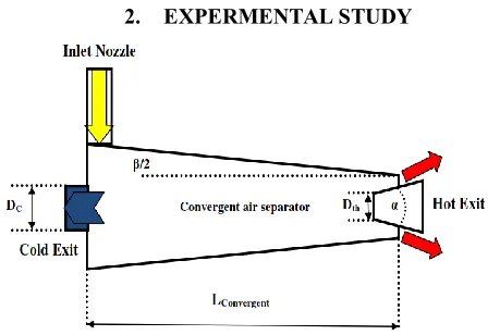
Fig. 2 A schematic drawing of the convergent air separator with
geometrical parameters
Table 1 Structural parameters
Length of convergent main tube 185mm
Diameter of cold exhaust 9 mm
slots number 2, 3, 4, 6
The shape of control valve Truncated cone
Nozzle section 2×1.7
Angle of throttle valve 30deg
Convergence angle 2 deg
Throttle diameter 4, 4.5, 5, 5.5, 6 and 6.5 mm
3 the separation phenomenon of the compressed air as the operational fluid. A steel convergent VT cyclone separator is designed with structural parameters as shown in Table 1.
Fig. 3 Schematic drawing of the experimental setup.
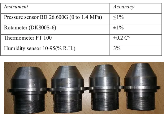
Also the schematic approach of the experimental set up utilized in the investigation is shown in Fig. 3. The system is designed so that all components have the ability to change, specially the conical valve and the convergent main tube. The changeable design makes the capability to study the effects of several structural parameters on the convergent VT cyclone separator performance. Room temperature was 21 degrees during the tests. The measuring instruments with details are listed in the Table 2.
Table 2 Measuring instruments
Instrument Accuracy
Pressure sensor BD 26.600G (0 to 1.4 MPa) ≤1%
Rotameter (DK800S-6) ±1%
Thermometer PT 100 ±0.2 C°
Humidity sensor 10-95(% R.H.) 3%
Fig. 4 The photographs of control valves with different throttle diameter(in comparison form) used in the tests
Six different hot control valves with different diameters have been manufactured and used in the tests. Two Ø2 mm holes are drilled on the VT cyclone separator axis for adjusting the thermo probes. The distances between the exhausts (cold and hot) and the holes are considered to be 1.25 cm. Before beginning the tests, the hot valve is adjusted in the open situation. In the next stage the tank starts to work. The used pressure (0.45 MPa) in the cycle is supplied by the action of the valve set on the inlet of the VT cyclone separator. The pressures and the mass rates are measured by the pressure sensors and the rotameters during the tests. Then, each convergent VT cyclone separator with specified parameters is tested. The
test processes are repeated several times for each parameter to determine the reliable values for the exhaust temperatures and pressures. The photographs of some control valves (in comparison form) used in the tests are shown in Fig. 4.
In this section, the uncertainty and the error analysis regarding the measurements of the pressure and temperature are discussed. A differential method is presented by Moffat (1985) to estimate the maximum temperature and pressure uncertainties. This method uses two parameters namely instrument accuracy and minimum values of output for estimating the errors. We assumed that an especial quantity like g is calculated by some independent variables such as yi, so the value of error for g is estimated by:
2
1( )
n i i y g g y
(1)In the present equation the terms of
y
i, yi and i iy y
represent the
minimum value of the independent parameter, the measuring instruments accuracy and the error of the independent parameter, respectively. The accuracies of the pressure and the temperature are 0.025 bar and 0.2 C respectively. Also the logged pressure and the temperature accuracies are 0.01 bar and 0.1 C. So, we can calculate the maximum errors for the pressure and the temperature as bellow:
Logged
2 2 2 2
Thermometer
m m
0.2 0.1
( ) ( ) ( ) ( ) 0.017 1.7
T T 13 13
T T T T % Logged
2 2 2 2
Sensor
m m
0.025 0.01
( ) ( ) ( ) ( ) 0.024 2.4
P P 1.1 1.1
P P P P %
3.
NUMERICAL APPROACH
3.1
Equations
The fluid stream has a compressible pattern with the high rotational specifications, so the RSM turbulence model is applied to solve the nonlinear equations (conservation of momentum, mass and the energy equation) of flow streams inside the tested convergent VT cyclone separator. A numerical model (three dimensional) is developed to predict the fluid treatment inside the convergent VT cyclone separator. This model is employed to create an accurate validation between the experimental and the numerical outputs. This model is executed by a finite volume commercial code (Fluent 6.3.26) using the steady state conditions. Then we have the equations of conservation of mass, momentum and energy which are provided as bellow:
.( ) Sm
t (2)
The fluid flow in the present work is considered to be steady, so the term
t
is equal to zero. If any mass flow is entered to the domain, the term Sm is added to the equation. In other words, this term refers to the additional mass entering to the main domain.
Momentum equation: ) ( 3 2 )
( i j
j k k ij i j j i j i j i j u u p x x u x u x u x x u u
x
(3) Energy equation: eff ij i j eff j j j i
i
u
u
u
x
k
x
u
x
T
h ( )
2 1
Prp tt
eff
c K k
(4)
4
RT
P (5)
The Fluent software provides the (RSM) Reynolds stress model as the most elaborate numerical modeling to simulate the full turbulent rotational flows. The transport equations have been solved together with the equation of dissipation rate to close the Reynolds-averaged Navier-Stokes equations by the RSM (Abandoning the isotropic eddy-viscosity assumption). So, seven transport equations are solved in the three-dimensional issues, while, five transport equations are required to be solved in the two dimensional problems.
This model has several advantages compared with other models (two-equation or one-equation models). Some of these benefits can be listed as: (a) considering the streamline curvature effect and involving the impact of the sharp changes in the rate of strain and (b) modeling the high rotational and swirl patterns. These great potentials and excellent performances convince the researchers to use this model, in spite of a lot of time to solve the 3D problems by this model. The main transport equations of the Reynolds stresses,
i j
u u
, can be written as bellow:
, ,
( ) ( ) [ ( )] [ ]
ij T ij L ij
i j k i j i j k kj i ik j i j
k k k k
C D D
u u u u u u u u p u u u u
t x x x x
( ) ( ) ( )
ij
ij ij
j i i j
i k j k i j j i
k k G j i
P
u u u u
u u u u g u g u p
x x x x
2 2 ( )
ij ij
j i
k j m ikm i m jkm user
k k
F
u u
u u u u S
x x
(6 )
where Suser, Fij, ɛij, ϕij, Gij, Pij, DL, ij, DT, ij, Cij and ( )
i j
u u
t
are considered
as User-Defined Source Term, Production By System Rotation, Dissipation, Pressure Strain, Buoyancy Production, Stress Production, Molecular Diffusion, Turbulent Diffusion, Convection and Local Time Derivative, respectively. In Equation (6), some terms such as Fij, Pij, DL, ij and Cij don’t require any discretizing. However some terms (ɛij, ϕij, Gij and DT, ij) should be discretized and modeled to manage the Eq (6). A complete explanation is provided in Ref [52].
3.2
Physical simulation
3. 2. 1. Modeling
The three dimensional numerical model developed in the numerical section is created on basis of the exact structural parameters of the real model. This means that the geometrical parameters are completely similar to the laboratory model (Table 1).
In the numerical simulation and the experimental study, the cold diameter of the VT cyclone separator is 9 mm as the fixed property. The flow pattern and the rate of energy separation are changed by changing the mentioned parameters (throttle diameter and slots number), and then these changes appear as a change in output temperatures. This research uses a 3D model to provide a clear observation for the process of energy separation inside the convergent VT cyclone separator.
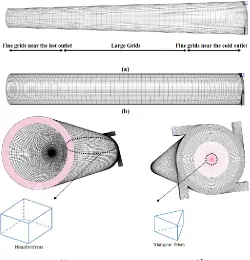
The variations in the axial and tangential velocities also the total pressure are presented in comparison form to analyze the flow properties. There are different meshing methods (Unstructured and Structured); each can be usable to different geometries. The better the mesh quality leads to the greater and faster the convergence rate. In other words, the correct solving has been achieved faster. It should be said that the accuracy of the results is very important near the outlets, so this issue shows the importance of using the finer mesh grids near the hot and cold outlets
(Fig.5 a). A normal VT cyclone separator with the straight main tube is shown in Fig. 5b (compared with convergent one). In the following, we have a solution with more accuracy using a better mesh quality.
Furthermore the CPU time is an important factor in the computational problems. In some problems which the quality of the arrangement of the cells is not efficient, the CPU time needed can be relatively increased. The CPU time will usually be proportional to the quality of the mesh grids. In three dimensional modeling, there are 3-dimensional elements namely; hexahedron , quadrilateral pyramid and tetrahedron. For the same number of elements, the accuracy of solutions has the highest value using the triangular prism and the hexahedral meshes. So these two types of mesh units have been used in the developed model as seen in Fig. 5c and 5d.
The volume around the center line of the VT cyclone separator is arranged by the triangular prism units; consequently the rest volume is made by the hexahedral meshes. So, in this way, both time and accuracy are combined together and produce the reliable results. The turbulence intensity of the air flow in the VT cyclone separator is so high, so that the conventional numerical methods have not the ability to solve the equations in this instrument. The URFs (Under-relaxation factors) play an important role in the process of the computation. It should be said that these factors determine the development path of the calculations.
The calculations should be a step by step process. The number of stages is determined by the URFs. In fact, the calculation, in this way, significantly increases the stability of the solution. In this article, the URF's changes have been proposed to solve the equations of the flow pattern in the convergent VT cyclone separator to be used by researchers (as seen in Table 3). First and Second Order Schemes (intermittent) are applied for the pressure discretization, since according to the CFD experiences, these combinations work better than other Schemes for both the swirling flow with high rotational speed (1000000 rpm) and the steep pressure variation.
Fig. 5 Schematic demonstration of mesh domain and the shape of the
unit volumes, (a) Convergent air separator, (b) Straight air separator, (c) Control valve position, (d) Nozzle injectors position
5 research, the convergences have been occurred in the range of 150000 to 210000 iterations. The changes of the values for the URFs are presented in Table 3, step by step.
Table 3 Under-relaxation factors used for computations
URF Step
1 2 4 5 7 8 10 11
Energy 0.1 0.2 0.4 0.5 0.7 0.8 0.95 1 Turbulent
Dissipation Rate
0.1 0.1 0.2 0.3 0.5 0.5 0.7 0.8
Body Force 0.1 0.2 0.4 0.5 0.7 0.8 0.95 1 Reynolds
Stresses 0.1 0.15 0.25 0.3 0.4 0.45 0.5 0.5 Density 0.1 0.2 0.4 0.5 0.7 0.8 0.95 1
Turbulent
Viscosity 0.1 0.2 0.4 0.5 0.7 0.8 0.95 1 Turbulent
Kinetic Energy
0.1 0.1 0.2 0.3 0.5 0.5 0.7 0.8
Momentum 0.1 0.1 0.2 0.3 0.4 0.4 0.6 0.7 Pressure 0.1 0.1 0.1 0.2 0.2 0.3 0.3 0.3
3. 2. 2. Boundary conditions
The computational domain requires the boundary conditions which are shown in Fig. 6. At the hot exit (bottom) and the cold exhaust (top) of the CFD domain, the Pressure Outlet boundary conditions are assumed. On the wall of the 3D model, the adiabatic boundary condition is applied (there is no heat transfer between the convergent VT cyclone separator and the ambient air), consequently, the convection effect is neglected here. There is a No-slip boundary-condition between the wall and the rotational flow inside the VT cyclone separator. The other boundary conditions are applied as follow: the nozzle slots (injectors) is set as the pressure inlet (Experimental values) with the pressure 0.45 MPa. The slots surface temperature is adjusted to 294.2 K (ambient temperature). The operating fluid inside the convergent VT cyclone separator is considered to be air with the ideal gas properties, so1.4.So the boundary conditions can be summarized as below:
(1) At the slots of the injectors, the boundaries are modeled as the
Pressure Inlet, with the specified pressure value at 4.5 bar and the fixed stagnation temperature at 294.2 K.(2) Cold and hot exits set as the Pressure-Outlet.
(3) The walls around the domain are set to be the Adiabatic Boundary Conditions, also with no slip properties.
Fig. 6 Boundary conditions required for the simulation
3. 3. Grid independence study
Before beginning the process of the numerical modeling, calculation or simulation, the grid independence check is very important. According to this fact, six different numbers of the unit cell volumes are examined as reported in Fig. 7. A convergent VT cyclone separator with a truncated cone throttle valve (for
2
deg, α=30 deg, Dth=4 mm,Lconvergent=185mm and D cold=9 mm as the basic model) was modeled with different unit cell volumes to guarantee the mesh sensitivity and the grid independence of the numerical outputs. Fig. 7 focuses on the predicted cold temperature difference at the location of the cold exhaust for the domains with 0.95 million (denoted ‘‘coarse’’), 1.12 million, 1.44 million (denoted "medium"), 1.67 million, 2.02 million and 2.35 million (denoted "fine") unit volumes. The influence of the mesh resolution and the discretization schemes can be explained (in this case) by comparing the cold temperature differences (Fig. 7). As seen in Fig. 7, the comparison of different unit cell volumes or the resolution of the mesh grids proves that the calculation obtained applying 2.02 million units have the competency to be the mesh independent model as the relative difference in maximum cold temperature difference (cold mass fraction α=0.27) applying 2.02 million units and 2.35 million units (denoted "fine") is less than 1.31%. This represents that enhancing the unit volume number has no necessary change in the accuracy of the results. To decrease the computational time and the cost, we choose 2.02 million unit cell volumes in all our models.
Fig. 7 Maximum cold temperature difference obtained with
different average unit cell volumes
4.
RESULTS AND DESCUSION
To create a clear insight into the effects of throttle diameter, slots number and injection pressure on the separation capabilities of the convergent VT cyclone separator (resulting from the exhausts), some experiments and numerical simulations as parametric studies are presented. This research focuses on the use of the convergent VT cyclone separator in various structural conditions, in other words, what different operating conditions or structural parameters can have the sensitive effect on the separation performance of the VT cyclone separator equipped with convergent main tube. So, this research tries to present the optimum values for the mentioned parameters to create the best possible separation capability (for the convergent VT cyclone separator) applying both experiments and CFD methods (RSM). This involves some terms such as; (a) testing the effects of six different throttle diameters (4-6.5mm), (b) the effect of applying different slots numbers (inside the chamber), and finally (c) the thermal reactions of the convergent VT cyclone separator against different operating pressures (Pi=0.45, 0.55, 0.65MPa with compressed air) have been analyzed. The separation capabilities of the convergent VT cyclone separator can be represented as ΔTc and ΔTh which are defined as following equations:
Cooling Inlet Cold
T
T
T
(7)Heating Hot Inlet
T
T
T
(8)The cold flow fraction is an important factor in the calculation of the convergent VT cyclone separator efficiency, because this is an output parameter which defines the flow rate of the cold exhaust. This important parameter is obtained by dividing the rate of the cold flow by the rate of the inlet flow. Equation (9) shows this relation by:
c
i
m m
(9)As mentioned before, the cold air flow is managed by the control valve performance. So, this part of the system has a direct impact on the
11 12 13 14 15 16 17
0 0.05 0.1 0.15 0.2 0.25
ΔT
c
/K
Average unit cell volume (mm3)
6 separation efficiency. Therefore, the optimal design of this part of the system can have a significant influence on the performance of the convergent VT separator system. So, in the first step, we try to optimize this part of convergent VT cyclone separator.
4. 1. Experimental Results 4. 1. 1. Effect of throttle diameter
In the preliminary analysis, the effects of throttle diameter of the valve (Dth) on the heating ability and cooling effectiveness of the convergent VT cyclone separator are investigated experimentally. Six conical valves with different throttle diameters Dth are utilized in the experiments with the diameter ofDth4, 4.5, 5, 5.5, 6 and 6.5mm .
The convergence angle of main tube, the throttle angle, the length of convergent main tube and the slots number for all the convergent VT cyclone separator were adjusted equal for a correct comparison. The hot and cold temperature drops are presented in Figs. 8 and 9, this result can be achieve that, the cold and hot temperature differences (cold and hot thermal drops ΔTc and ΔTh ) are highest at Dth=5.5mm (the optimum value for the throttle diameter in experimental tests).
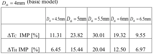
So, the analyzed range of the throttle diameter can be divided into two subsets, which the first subrange contains the diameters that are smaller than 5.5 mm, and the second subrange contains the diameters that are larger than 5.5 mm. It can be seen from Figs. 8 and 9 that, for the first subrange, the smaller throttle diameters provide smaller hot and cold temperature drops. Also, the heating and the cooling (flow separation) capabilities increases extremely with an increase in the throttle diameter up to Dth= 5.5 mm, then beyond Dth= 5.5 mm, the heating and the cooling capabilities are decreased. The details of the heating and the cooling improvements are presented in Table 4 (This table is taken from Figs. 8 and 9).
According to Table 4, the convergent VT cyclone separator equipped with a throttle valve with Dth = 5.5 mm provides 30.01 % higher cooling temperature drop and 20.04 % higher heating temperature drop as compared to basic model (Dth = 4 mm). So, the convergent VT cyclone separator with throttle diameter of 5.5 mm provides best separation (both cooling and heating) performance among all the convergent VT designs. Therefore, the conical valve with 5.5 mm throttle diameter has been selected for performing further investigations for the design of the optimum convergent VT cyclone separator.
Fig. 8 The effects of throttle diameter of the valve(Dth) on heating performance of convergent air separator
Fig. 9 The effects of the throttle diameter of the valve(Dth) on cooling performance of convergent air separator
Fig. 10 The effect of throttle diameter of the control valve (Dth) on convergent air separator efficiency
Table 4 Cooling and heating improvements of the convergent VT air separator with different values of Dth as compared to
4mm
th
D (basic model)
4.5mm th
D Dth5mmDth5.5mmDth6mmDth6.5mm
ΔTC IMP [%] 11.31 23.82 30.01 19.32 9.55
ΔTH IMP [%] 6.45 15.44 20.04 12.50 6.97
Also, in this case (convergent VT); the change in the location of optimum cold mass fraction is almost negligible with increasing throttle diameter from 4 to 6.5 mm (Fig. 9). In other words, the behavior of the optimum cold flow ratio point is not significantly affected by the throttle diameter.
The isentropic efficiency is evaluated utilizing the following equation:
1 Isentropic Isentropic [1 ( ) ]
Cold Inlet Cold Inlet Cold
is
Inlet Atm
Inlet Inlet
T T T T T
T T T T P
P
(10)
5 7 9 11 13 15 17 19 21 23 25
0 0.2 0.4 0.6 0.8 1
H
ea
ti
n
g
E
ff
ec
ti
v
en
es
s
(Δ
T
h
/K
)
Cold Mass Fraction
β=2 deg
P=4.5 bar
α=30 deg
Dth=4 mm Dth=4.5 mm
Dth=5 mm Dth=5.5 mm
Dth=6 mm Dth=6.5 mm
6 8 10 12 14 16 18 20 22 24
0 0.2 0.4 0.6 0.8 1
C
oo
lin
g
E
ff
ec
ti
ve
n
es
s (
Δ
T
c/
K
)
Cold Mass Fraction
β=2 deg P=4.5 bar
α=30 deg
Dth=4 mm Dth=4.5 mm
Dth=5 mm Dth=5.5 mm
Dth=6 mm Dth=6.5 mm The optimum cold flow raio position
0 5 10 15 20 25
0 0.2 0.4 0.6 0.8 1
η
%
Cold Mass Fraction
β=2 deg α=30 deg P= 4.5 bar
7 where
P
Atm,P
Inlet,T
Coldand
T
Isentropic represent the ambient pressure, the injection pressure, the cold exhaust temperature and the isentropic temperature drop, respectively. Fig. 10 shows the isentropic efficiency for the convergent VT cyclone separator equipped with different control valves with different throttle diameters. As seen in Fig. 10, the best efficiency is provided by the throttle diameter of 5.5 mm. The cooling efficiency of the convergent VT cyclone separator with Dth=5.5 mm is 22.34 % at the cold mass fraction of 0.27, which creates 5.16 % higher cooling efficiency as compared to basic model (Dth=4 mm). For greater and smaller diameters than 5.5 mm the efficiency allays.4. 1. 2. The slots number effect
In the case of straight VT cyclone separator, Rafiee and Rahimi (2013) stated thatthe cold temperature drop improves by 45.7 percent (11.9°C) as the nozzle slot number increases from 2 to 6. In other words, the cooling effectiveness increases continuously with an increase in the nozzles number.
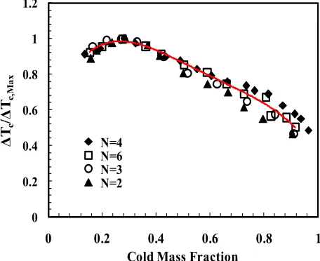
So the nozzles number has very impressive effect on the cooling performance of the VT cyclone separator with straight main tube. Fig. 11 shows the variation of cooling effectiveness of the optimum convergent VT cyclone separator with cold mass fraction for different nozzles (slots) numbers. Unlike the conclusion provided by Rafiee and Rahimi (2013) (in the case of straight VT cyclone separator), this research proves that the convergent VT cyclone separator has a different reaction against increasing the slot number. The cooling effectiveness improves sharply with an increase in the slot number up to N= 4 (the basic model has 4 slots), then beyond N= 4, the cooling effectiveness decreases (nominal).
It can be seen that the cooling effectiveness has the lowest values at minimum slots number N=2. As slot number is increased from 2 to 4, the cold temperature difference increases by 16.86%. The physical reason can be explained in this way; when the slots number is increased from 2 to 4, the turbulence kinetic energy improves, and then beyond 4 slots, it becomes constant (approximately). This is on basis of the fact that the pressure and the velocity drops increase as the increasing number of slots in the range of 2 to 4, then this event is also seen with an enhance in the cold temperature drop when the slots number is increased from 2 to 4. According to the statements, it can be concluded that, by increasing the slot number, the level of turbulence improves in the convergent VT cyclone separator, which leads to an increase in the cold temperature drop.
Fig. 11 Impact of number of slots on cold temperature drop
as a function of cold mass fraction for the optimum model (
2deg,
30deg, Dth5.5mm and L=185 mm)An investigation has been conducted on similar VT cyclone separator equipped with straight main tube by Stephan et al. (1983). Their results
show that the ratio of the cold temperature drop to the maximum temperature drop illustrates a special fraction which varies only with the cold flow fraction as bellow:
,max ( )
c
c
T f
T
(11)
According to Fig. 12, the Stephan's theory is confirmed for the slots numbers. As seen in Fig. 12, it can be said that the variation of slots number does not vary the balance of the pressure patterns, so the optimum cold flow fraction is not changed. The similarity relation for the slots number can be reported as bellow:
4 3 2
6.093 14.30 12.45 4.034 0.553
y x x x x (12)
The Equation (12) (reported from Fig. 12), indicates that the ratio of
,max
c
c T T
for the convergent VT cyclone separators is independent of the slots number, and can be reported as only one variable parameter namely cold flow fraction.
Fig.12 Effects of slots number on non-dimensional cold
temperature drop as a function of cold flow fraction
Fig. 13 Verification of the similarity relation for the present work, the similarity relation for different works are compared against each other (with different optimum cold mass fraction)
5 7 9 11 13 15 17 19 21 23 25
0 0.2 0.4 0.6 0.8 1
C
o
o
li
n
g
E
ff
ec
ti
v
en
es
s
(Δ
T
c/
K
)
Cold Mass Fraction
β=2 deg α=30 deg P= 4.5 bar Dth=5.5 mm
L=185 mm
N=4 N=6 N=2 N=3
0 0.2 0.4 0.6 0.8 1 1.2
0
0.2
0.4
0.6
0.8
1
ΔT
c
/Δ
T
c,Max
Cold Mass Fraction
N=4 N=6 N=3 N=2
0.2 0.3 0.4 0.5 0.6 0.7 0.8 0.9 1 1.1 1.2
0 0.2 0.4 0.6 0.8 1
ΔT
c
/ΔT
c,
M
a
x
Cold Mass Fraction
Prasent Work
Hilsch (1947)
Stephan et al. (1983)
8 The results by Stephan et al. (1983), Farzaneh-Gord et al. (2014) and Hilsch (1947) are employed to verify the similarity equation for the present convergent VT cyclone separator. The variation of
,max
c
c T T
with
the cold flow fraction is presented for four different works in Fig. 13. The results of
,max
c
c T T
for different researches are showing the same trend but with different optimum cold mass fractions (red lines). The red lines determine the point of the optimum cold flow fraction for each VT cyclone separator. This difference refers to the dissimilarity of the pressure balance inside the used VT cyclone separators. The structural parameters of the VT cyclone separators in other researches (which are compared to our convergent VT cyclone separator) are presented in Table 5.
Table 5 The VT air separators applied by other researchers compared to present work
Dcold
(mm) Shape Tube Slots Tube Length (mm) Shape of Control Valve Present
Work 9 Convergent 4 185 Truncated
Hilsch (1947
2.6 Straight 1 300 cone
Stephan et al. (1983)
6.5 Straight 1 352 cone
Farzaneh-Gord et al.
(2014)
7.76 Straight 6 95.2 N/A
Fig. 14 The pressure effect on the cooling performance of
convergent air separators
In this section, to evaluate the effect of injection pressure on cooling effectiveness of convergent vortex tube, three different values of injection pressure (4.5, 5.5 and 6.5 bar) have been applied on the convergent VT cyclone separator, and the results are shown in Fig. 14. As a result, the higher injection pressure, the higher cold temperature difference, so the increasing injection pressure at the injectors is a favor factor which causes a better energy separation inside the convergent VT cyclone separator and greatly increases the convergent VT cyclone separator performance.
As another result, the cold temperature difference improves more seriously with an increase in the injection pressure upto P= 5.5 bar and beyond P= 5.5 bar the increase in the cold temperature difference is nominal. According to Fig. 14, when the pressure is increased from 4.5 to 5.5 bar, the cooling performance is increased by 23.39%, and, for 5.5 to 6.5 bar this improvement is equal to 8.15%.
4. 2. Numerical Results 4. 2. 1. Validation
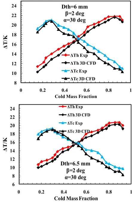
In the following, the three dimensional numerical results are validated through a comparison with the experimental outputs. In this way, to validate the computational data, the computed outputs are compared with the laboratory results gained in the experimental section. Fig. 15, Table 6 and 7 demonstrate the comparison result between the temperature results of the real model (with six throttle valve diameters) and the three dimensional computing which was considered as same as the geometrical and the operating conditions of the real case. Fig. 15 shows the temperature differences at the hot and cold exhausts of the convergent VT cyclone system with four nozzle slots, an injection temperature of 294.2 K and the pressure of 0.45 MPa.
The comparison between the computed and the laboratory outputs presents a favorable consent even though some disagreements exist at some temperature points. The average and the maximum disagreements between the experimental quantities and the predicted values of the cold temperature difference are 2.59% and 6.25%, respectively. Also, the average and the maximum values regarding the disagreements between the experimental data and the predicted values for the hot temperature difference are 1.95 % and 2.51 %. These validations depict that the simulations can present the successful and reliable predictions regarding the laboratory sets. The quantified and detailed presentation of the disagreements regarding the cold temperature difference at the cold mass fraction of 0.27 (optimum cold flow fraction for cooling effectiveness) is described in Table 6.
According to Table 6, the cold temperature drop values confirm the experimental measurements with 1–6.25% disagreement. As the result of Table 7, it can be seen that, the hot temperature difference results agree very well with the experimental results including a deviation in the range of 0.91–2.51 %. The disagreement between the experimental results and the CFD predictions is due to some assumptions (in this case, the walls of convergent VT cyclone separator are adjusted as adiabatic boundary condition) which are considered in the simulations.
Table 6 The disagreement between laboratory and measured results for cold thermal drop at optimal cold flow ratio
Throttle Diameter ΔTc Exp (K) ΔTc Num (K) Disagreement (%)
= 4 mm
th
D 17.59 16.49 6.25
= 4.5 mm
th
D 19.58 18.96 3.16
= 5 mm
th
D 21.78 21.22 2.57
= 5.5 mm
th
D 22.87 22.57 1.31
= 6 mm
th
D
20.99 20.78 1.00= 6.5 mm
th
D 19.27 19.02 1.29
Table 7 The disagreement between laboratory and measured results for hot thermal drop at optimal cold flow ratio
Throttle Diameter ΔTh Exp (K) ΔTh Num (K) Disagreement (%)
= 4 mm
th
D 19.36 18.91 2.32
= 4.5 mm
thD
20.61 20.13 2.32= 5 mm
th
D 22.35 21.89 2.05
= 5.5 mm
th
D
23.24 22.87 1.59= 6 mm
thD
21.78 21.58 0.91= 6.5 mm
th
D 20.71 20.19 2.51
8 13 18 23 28 33
0 0.2 0.4 0.6 0.8 1
C
oo
li
ng
E
ff
ec
ti
ve
ne
ss
(Δ
Tc
/K
)
Cold Mass Fraction
β=2 deg α=30 deg Dth=5.5 mm
L=185 mm
9
Fig. 15 Validation of the laboratory results and the outputs gained by the numerical modeling
In the case of pressure inlet and pressure outlet boundary conditions, the total pressure (
p
0
) and the static pressure (ps) are related as:0 2 1
0
1
(1
)
2
op
op
p
p
M
p
p
(13)
And:
s
v v
M
c
RT (14)
where, p
v C C
and c is the sound speed. It should be said that
p
op(operating pressure) comes in Eq (13), since our boundary condition inputs are defined as a function of pressure relative to operating pressure.
4. 2. 2. Contours
Because of the main objective of this investigation (study on the correlation between the flow separation and the energy pattern with different geometrical parameters) this is very important to describe some relevant factors within the convergent VT cyclone separator. The total temperature variations throughout the convergent VT cyclone separator are presented in Fig. 16. This is clearly certifiable that the total temperature of the region close the walls has the higher value compared to the central region. This temperature difference is very clear at entrance of the chamber (near the cold orifice) in comparison with other longitudinal areas. The volume of the cold core is constantly growing
5 7 9 11 13 15 17 19 21 23
0 0.2 0.4 0.6 0.8 1
Δ
T
/K
Cold Mass Fraction
Dth=4 mm
β=2 deg
α=30 deg
ΔTh Exp ΔTh 3D CFD
ΔTc Exp ΔTc 3D CFD
5 7 9 11 13 15 17 19 21 23 25
0 0.2 0.4 0.6 0.8 1
Δ
T
/K
Cold Mass Fraction Dth=4.5 mm
β=2 deg α=30 deg
ΔTh Exp ΔTh 3D CFD
ΔTc Exp ΔTc 3D CFD
8 10 12 14 16 18 20 22 24 26
0 0.2 0.4 0.6 0.8 1
Δ
T
/K
Cold Mass Fraction Dth=5 mm
β=2 deg α=30 deg
ΔTh Exp ΔTh 3D CFD
ΔTc Exp ΔTc 3D CFD
8 10 12 14 16 18 20 22 24
0 0.2 0.4 0.6 0.8 1
Δ
T
/K
Cold Mass Fraction Dth=5.5 mm
β=2 deg α=30 deg
ΔTh Exp
ΔTh 3D CFD
ΔTc Exp
ΔTc 3D CFD
8 10 12 14 16 18 20 22 24
0 0.2 0.4 0.6 0.8 1
Δ
T
/K
Cold Mass Fraction Dth=6 mm
β=2 deg α=30 deg
ΔTh Exp ΔTh 3D CFD ΔTc Exp ΔTc 3D CFD
6 8 10 12 14 16 18 20 22 24
0 0.2 0.4 0.6 0.8 1
Δ
T
/K
Cold Mass Fraction Dth=6.5 mm
β=2 deg α=30 deg
ΔTh Exp ΔTh 3D CFD
10
Dth=6 mm Dth=5.5 mm
Dth=4 mm (a)
(b)
Fig. 16 The local contours of temperature distribution for convergent VT
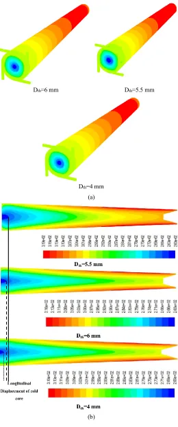
air separators with different throttle diameters; (a) 3D contours, (b) Longitudinal displacement of the cold core and the cross section contours
from bottom to top of Fig. 16 based on the cold exhaust temperature using different throttle diameters. In fact, the use of different values of throttle diameter causes an obvious change in the volume of the cold core. The volume of cold core belongs to Dth= 5.5 mm (Fig. 16 b) is the coldest core and has the highest volume in comparison with other control valves. The next control valve is Dth=6 mm which has the second place in the cold core volume list. In other words, Dth=6 mm is located into the second place in the highest cold volume and the lowest temperature rankings. The last position belongs to the control valve with Dth=4 mm. According to these results, this can be said that Fig. 16 confirms the results of Figs. 8 and 9 (experimental approach), completely.
In order to explain a clear understanding of the procedures happening inside the convergent VT cyclone separator, this section tries to analyze the flow pattern for these special cases involving the injection pressure equal to 0.45 MPa and the cold flow fraction equal to 0.27, which, corresponded to the laboratory operating conditions, and gives the lowest cold exhaust temperature. Fig. 17 describes the stream line structures within the developed convergent VT cyclone separators simulated by the RSM turbulence model. These patterns are shown on the longitudinal cross section of the convergent VT cyclone separators equipped with three different valves (with different throttle diameters). All the models emphasize on the creation of some recirculation areas named vortices near the chamber (cold exit) and near the control valve, which have different sizes and properties. It should be noted that, the larger the size of the vortices, the higher the level of mixing between the central cold core and the peripheral layers, so the separation capability of the convergent VT cyclone separator decreases with increasing size of the vortices. As seen in Fig. 17 (a), that's why the convergent VT cyclone separator equipped with the valve with Dth=4mm has the lowest cooling efficiency.
In this way, the flow inside this convergent VT cyclone separator has the highest amount or level of turbulence (turbulent viscosity Fig. 18). The convergent VT cyclone separator with the throttle diameter of Dth=4mm has two longitudinal vortices, while the rest of VT cyclone separators have three longitudinal vortices. This is because of the better aerodynamic shape of the valve of Dth=4mm which causes the fluid moves easily inside the main tube. Also Fig. 17 (a) shows the effect of level of turbulence on the location of the stagnation point. It can be pointed that the distance between the stagnation point and the control valve is limited by the amount or level of the turbulence. As said before, the convergent VT cyclone separator with Dth=4 mm has two vortices and the VT cyclone separators with Dth=5.5 mm and 6 mm have three vortices. According to Fig. 17 (a), it can be concluded that the development of third vortex has a very important role in improving system performance by moving the stagnation point towards the control valve. So that, the stagnation point gets closer to the valve with third vortex growth. Fig. 17 (b) demonstrates the process of stagnation point transfer along the main tube by the third vortex. Third vortex in the convergent VT cyclone separator with Dth=5.5 mm is more developed as compared to the convergent VT cyclone separator with Dth=6 mm, as a result, the stagnation point is closer to the valve in Dth=5.5 mm. So, the convergent VT cyclone separator with Dth=5.5 mm has the smallest distance between the stagnation point and the hot valve as well as the highest cooling ability.
On the other hand, the largest distance between that point and the valve belongs to the convergent VT cyclone separator with Dth=4 mm which has the lowest separation efficiency. It can be obvious from the explanations above that the cooling capability can moves to the maximum value by decreasing the distance between the stagnation point and the control valve as much as possible. Two top cases having the smallest distances between the stagnation point and the valve are the convergent VT cyclone separator with Dth=5.5 mm and 6 mm (because of third vortex). These results confirm the Nimbalkar and Muller [56] statements.
11 valve. Consequently, the convergent VT cyclone separator with Dth=5.5 mm has the best separation process and thermal performance among all simulated VT cyclone separators. In highly rotating and fully turbulent flow pattern within the domain of the convergent VT cyclone separator, the turbulent viscosity can be considered as the dominant parameter in comparison with the molecular viscosity [12], so the turbulent viscosity can play an important role to explain the amount of the turbulence during the energy separation process. Fig. 18 describes the turbulent viscosity contours inside the convergent VTs with different throttle diameters. As said before, the separation process quality was lower for the larger turbulent viscosities. The turbulent viscosity decreased by 26.64 % with an increase in the throttle diameter from 4 mm to 5.5 mm. also the turbulent viscosity at Dth=6 mm is 9.98 % higher than at Dth=5.5 mm. Consequently, for the convergent VT cyclone separators, the smaller level of turbulent viscosity provides relatively higher separation process quality or smaller vortices near the chamber.
In highly rotating and fully turbulent flow pattern within the domain of the convergent VT cyclone separator, the turbulent viscosity can be considered as the dominant parameter in comparison with the molecular viscosity [12], so the turbulent viscosity can play an important role to explain the amount of the turbulence during the energy separation process. Fig. 18 describes the turbulent viscosity contours inside the convergent VTs with different throttle diameters. As said before, the separation process quality was lower for the larger turbulent viscosities. The turbulent viscosity decreased by 26.64 % with an increase in the throttle diameter from 4 mm to 5.5 mm. also the turbulent viscosity at Dth=6 mm is 9.98 % higher than at Dth=5.5 mm. Consequently, for the convergent VT cyclone separators, the smaller level of turbulent viscosity provides relatively higher separation process quality or smaller vortices near the chamber.
(a)
(b)
Fig. 17 a) Structural plot of streamlines, vortices, location of stagnation point and the shrinking of vortices for three convergent VT air separators with different throttle diameters, b) Direction of stream lines around the third auxiliary vortex near the valve (Dth=5.5 mm)
Dth=4 mm
Dth=5.5 mm
Dth=6 mm
Fig. 18 Contour plot of turbulent viscosity for longitudinal sections in comparison form
The change of the rotational velocity for different convergent VT cyclone separators equipped with different control valves (with different throttle diameters) is shown in Fig. 19(a). This figure is presented for different streamwise sections (Z/L=0.1 and 0.7) along the main tube. Fig. 19(a) indicates that the rotational or the tangential velocity (along the radius) varies greatly with different throttle diameters. The maximum value of the tangential velocity is changed with the streamwise section and has a downward trend along the length of the hot tube. In this way, the largest possible rotational speeds are occurred at the entrance of the main tube (Z/L=0.1) then drops to the lower values as the gas expansion along the tube. As previously mentioned, the convergent VT cyclone separator with Dth=5.5 mm exhibits the highest rate of the energy separation, also, according to the results of Fig. 19(b) the highest value of maximum tangential velocity drop belongs to this convergent VT cyclone separator. So, this result can be picked up that the higher the maximum tangential velocity drop, the higher the cooling and separation efficiency.
This issue reflects the fact that the high tangential velocity drop and the high temperature difference are the results of the efficient expansion of the gas inside the chamber. Consequently, the VT cyclone separators with Dth= 4mm and 6.5 mm have the minimum rotational velocity drops as well as the lowest cooling capabilities. Fig. 20(a) presents the axial velocity variations on the radial lines in different axial sections. As seen, the axial velocity values consist of some positive and negative speed values in each axial section. It can be said that, the cross section area has been assumed as a velocity domain in which the velocity of the flow changes from a maximum positive value to a minimum negative magnitude. This issue shows that there is a reversal pattern for the axial velocity.
12 (a)
(b)
Fig. 19 (a) The radial plot for swirl (tangential) velocity, the swirl velocity varies with dimensionless radial distances and different throttle diameters (for different Z/L) Z/L=0.1, Z/L=0.7. (b) Maximum tangential velocity drop for convergent VT air separators with different throttle diameters
process (expansion), the particle temperature decreases sharply and the fluid particle redirects to the central cold region. The pressure difference acting on the particles creates an accelerating movement which increases the axial velocity towards the cold exit. As mentioned above, the convergent VT cyclone separator with Dth=5.5mm produces the highest cooling and separation capability, also, according to the results of Fig. 20(a) the highest value of axial speed belongs to this convergent VT cyclone separator and the VT cyclone separator with Dth=4 mm has the minimum axial velocity as well as the lowest cooling capability. Also, according to Fig. 20(b) the highest possible pressure values are occurred at the entrance of the main tube (Z/L=0.1) then drops to the lower values as the gas expansion along the tube. As mentioned before, the convergent VT cyclone separator with Dth=5.5 mm exhibits the highest rate of the energy separation, also, according to the results of Fig. 20(b and c) the highest values of the total pressure in the sectional locations (exactly in Z/L=0.1 and approximately in Z/L=0.7) and the maximum total pressure drop belong to this convergent VT cyclone separator.
(a)
(b)
(c)
Fig. 20 (a) The radial plot for axial velocity, the axial velocity varies with dimensionless radial distances and different throttle diameters (for different Z/L); (a) Z/L=0.1 (b) Z/L=0.7, (b) The radial plot for total pressure (Z/L=0.1 and Z/L=0.7), (c) Maximum total pressure drop for convergent VT air separators with different throttle diameters 0 50 100 150 200 250 300 350
0 0.2 0.4 0.6 0.8 1
S w ir l V el o ci ty ( m /s )
Dimensionless Radial Distance (r/R)
Z/L = 0.1
Dth= 4mm Dth= 6.5mm Dth= 4.5mm Dth= 6mm Dth= 5mm Dth= 5.5mm 0 50 100 150 200
0 0.2 0.4 0.6 0.8 1
S w ir l V el o ci ty ( m /s )
Dimensionless Radial Distance (r/R)
Z/L = 0.7
Dth= 4mm Dth= 6.5mm Dth= 4.5mm Dth= 6mm Dth= 5mm Dth= 5.5mm 128.595 121.882 135.105 146.239 155.326 167.848
Maximum Tangential Velocity Drop (m/s)
Dth= 5.5mm Dth= 5mm
Dth= 6mm Dth= 4.5mmDth= 6.5mm
Dth= 4mm -110 -90 -70 -50 -30 -10 10 30 50 70 90
0 0.2 0.4 0.6 0.8 1
A xi al V el oc it y (m /s )
Dimensionless Radial Distance (r/R) Z/L = 0.1
Dth= 4mm Dth= 6.5mm
Dth= 4.5mm Dth= 6mm Dth= 5mm Dth= 5.5mm
-70 -50 -30 -10 10 30 50
0 0.2 0.4 0.6 0.8 1
A xi al V el oc it y (m /s )
Dimensionless Radial Distance (r/R)
Z/L = 0.7
Dth= 4mm Dth= 6.5mm Dth= 4.5mm Dth= 6mm Dth= 5mm Dth= 5.5mm 0 50 100 150 200 250 300 350
0 0.2 0.4 0.6 0.8 1
T ot al P re ss u re ( k P a)
Dimensionless Radial Distance (r/R)
Z/L=0.1 Dth= 5mm Dth= 6mm Dth= 4.5mm Dth= 6.5mm Dth= 4mm Dth= 5.5mm 40 60 80 100 120 140
0 0.2 0.4 0.6 0.8 1
T ot al P re ss u re ( k P a)
Dimensionless Radial Distance (r/R) Z/L=0.7 Dth= 5mm Dth= 6mm Dth= 4.5mm Dth= 6.5mm Dth= 4mm Dth= 5.5mm 208282 174074 167910 162177 157659 146693
Maximum Total Pressure Drop (kPa)