126 Available online at www.ijiere.com
International Journal of Innovative and Emerging
Research in Engineering
e-ISSN: 2394 – 3343 p-ISSN: 2394 – 5494
Design and Implementation of Maximum Power Point
Tracking system for Solar PV Panels
Ketan Jore, Manish Kumar, Seema Jadhav, Aleena Babu, Andrick D’souza
Department of Electrical Engineering,Fr. C. Rodrigues Institute of Technology, Vashi, Navi Mumbai.
ABSTRACT:
The non-renewable energy sources are depleting fast and the solar energy has emerged as a future alternative energy source. It has limitations like less reliability, high installation cost and low conversion efficiency. In this paper, an efficient DC-DC boost converter is designed to step up the voltage from the solar panel and supply to the load. A digital signal processor is used to implement the MPPT algorithm to extract the maximum power from the solar panel at any instant of time. The circuit is simulated in MATLAB simulink and results are verified by hardware implementation. The power extracted can also be used to charge the batteries and can be used to supply power to loads when solar power is unavailable.
Keywords:Boost converter, converter efficiency, Incremental conductance, MPPT.
I. INTRODUCTION
In modern era, the consumption of electrical energy is increasing at very rapid rate with the increasing population. To fulfil this increased demand of electricity the conventional energy resources such as coal, oil, gas etc are consumed at very fast rate and thus they are on the verge of depletion. To find the solution to above problem, now the focus is on the renewable energy sources. These are the alternative energy resources that can be renewed and have no concern of depletion [1].
Solar energy is one of the most widely used renewable energy sources for generating electricity. Solar energy is most clean source of energy as it does not cause any kind of pollution as compared with conventional energy resources. Solar energy is an unlimited resource available in nature and set to become important in longer terms for providing heat and electricity to the user. In the last decade, there was a consistent development in the worldwide market of photovoltaic system. By the end of year 2008, 13GW of energy had been generated by the installed PV systems throughout the world [2].
There are many issues with solar photovoltaic system: the output power changes with the change in temperature, incident solar radiation and other environmental conditions. Also the output power is not available for complete twenty four hours and throughout the year. The main drawback with solar system is the efficiency. It has been found in literature that the efficiency of the PV system can be increased by improving the conversion efficiency of solar cell i.e. an improvement of the solar cell material but this single factor is not enough to get the maximum power at load. So, maximum power point tracking (MPPT) system is developed to track the maximum the power available from solar PV panels [3].
Many algorithms for maximum power point tracking are proposed and verified in past. One of the simplest method is the Perturb and Observe, also called “Hill climbing”, proposed by F. Iov et al [3, 4].It has the major drawback of oscillations near the MPP. Similar algorithm called Incremental Conductance (INC) was developed by Rosa A. Mastromauro et al [4]. This method intends to improve the P&O by replacing the derivative of the power versus voltage dP/dV used by the P&O with the PV panel instantaneous conductance (I/V) and incremental (dI/dV) conductance. Another method for maximum power point tracking is Constant Voltage (CV) method described by Ryousuke Nambaet al[5,6]in which maximum power point of the PV panel voltage changes slightly with irradiation. Open circuit and slope detection tracking algorithm was developed by Chih-Yu Yang et al. which overcomes the drawback of constant voltage algorithm. A variable step perturbation technique (VSP) is used after the slope detection tracking technique to accelerate tracking speed and minimizing oscillation problem [7].
127 Fig. 1 Basic block diagram of MPPT system
In this paper, the incremental conductance method is implemented for extracting maximum power from solar PV panels. The paper is arranged as follows: Section II explains Block diagram of the complete system, Section III describes design of the DC-DC converter as per the specifications of the solar panel, Section IV presents simulation and hardware results, Section V concludes about the efficiency. The block diagram of the complete system is explained briefly in the next section.
II. DESIGNOFBOOSTCONVERTER
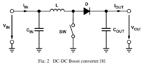
Before starting with design, we must understand the working of boost converter. In this converter, the output voltage is greater than the input voltage. A boost converter using a power MOSFET (SW) is shown in Fig.2.
Fig. 2 DC-DC Boost converter [8]
Mode 1: When SW is ON at time t=0. The input current rises and flows through inductor L and SW.
Mode 2: When SW is OFF at time t=t1. The input current now flows through L, diode D,Cout and load. The inductor current falls until the next cycle. The energy stored in inductor L flows through the load. The design of DC-DC converter involves following calculations.
i) Calculation of Duty cycle: To calculate the duty cycle D, minimum input voltage because this leads to the maximum switch current. The duty cycle of the switch is given by equation (1).
𝐷 = 1 −𝑉𝐼𝑁(𝑀𝐼𝑁)× η 𝑉𝑂𝑈𝑇
(1)
where𝑉𝐼𝑁(𝑀𝐼𝑁) = minimum input voltage, 𝑉𝑂𝑈𝑇 = desired output voltage, η = efficiency of the converter, e.g. estimated
95% to 100%.
ii) Inductor ripple current:Maximum switch current is required to determine the inductor ripple current using equation (2).
∆𝐼𝐿=
𝑉𝐼𝑁(𝑀𝐼𝑁)× 𝐷
𝑓𝑆× 𝐿
(2)
where𝑓𝑆= minimum switching frequency of the converter, L=selected inductor value.
iii) Maximum switch current:Now maximum switch current is determinedto know whether the selected IC can deliver the maximum output current using equation (3).
𝐼𝑀𝐴𝑋(𝑂𝑈𝑇)= (𝐼𝐿(𝑀𝐼𝑁)−
∆𝐼𝐿
2 ) × (1 − 𝐷) (3)
where 𝐼𝐿(𝑀𝐼𝑁)= minimum value of the current limit of the integrated switch (given in the data sheet), ∆𝐼𝐿 = inductor ripple
current.
128
𝐿 =𝑉𝐼𝑁× (𝑉𝑂𝑈𝑇− 𝑉𝐼𝑁) ∆𝐼𝐿× 𝑓𝑆× 𝑉𝑂𝑈𝑇
(4)
The inductor ripple current cannot be calculated because the inductor is not known. A good estimation for the inductor ripple current is 10% to 20% of the output current. The ripple in inductor current is given by equation (5).
∆𝐼𝐿= (0.1 𝑡𝑜 0.2) × 𝐼𝑂𝑈𝑇(𝑀𝐴𝑋)×
𝑉𝑂𝑈𝑇
𝑉𝐼𝑁
( 5)
where𝐼𝑂𝑈𝑇(𝑀𝐴𝑋)= maximum output current necessary in the application.
v) Selection of Output Capacitor: Best practice is to use low ESR capacitors to minimize the ripple on the output voltage. Generally output ripple voltage is about 5% of output voltage.Output capacitor values for a desired output voltage ripple is calculated as in equation (6)
𝐶𝑂𝑈𝑇 =
𝑉𝑂𝑈𝑇× 𝐷
2 × 𝑅𝑂× 𝑓𝑆× ∆𝑉𝑂𝑈𝑇
(6)
where𝐶𝑂𝑈𝑇= output capacitance, ∆𝑉𝑂𝑈𝑇 = desired output voltage ripple.
v) Selection of diode: The diode is selected such that itsforward current ratingis equal to the maximum outputcurrent i.e. 𝐼𝐹= 𝐼𝑂𝑈𝑇(𝑀𝐴𝑋)where 𝐼𝐹= average forward current of the rectifier diode and 𝐼𝑂𝑈𝑇(𝑀𝐴𝑋)=maximum output current
necessary in the application [8,9]. The calculated values of components for Boost converter are tabulated below in Table 1. The incremental conductance method is discussed in detail in next section.
Table 1. Calculated values of Components for Boost Circuit
III. .INCREMENTALCONDUCTANCEMETHOD
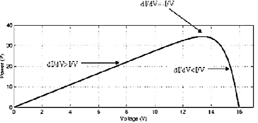
In order to continuously harvest the maximum power from the solar panels, it is necessary to control optimal impedance between the storage device and the PV cell, so that the system can be operated at their maximum power point (MPP), despite of the inevitable change in the environment. The MPPT control is a real time detecting panel output power and adapting the control algorithm to make the system operate under the optimum work state. MPPT system controls the impedance to track the maximum power point by sensing the current and voltage from the PV panel. Now, in order to sense the current and voltage from the panel, voltage and current sensor with additional analog circuit is required. Moreover, high speed energy storage device is needed to store maximum power which changes according to the climate conditions. This requirement can be fulfilled by using a controller like DSP, which reduces the need of separate analog circuits and act as an intelligent MPPT controller [5, 6]. The P-V characteristic of Solar PV panel is as shown in Fig 3.
Fig 3. P-V characteristics of solar panel [5,6 ]
Sr. no. Parameters Values
1 Duty Cycle 0.5
2 Input Voltage 30V
3 Output Voltage 60V
4 Inductor 350H
5 Ripple in Inductor current 1.6A
6 Output Capacitor 220F
129 The main objective of incremental conductance method is to find the distance of PV operating point from the Maximum Power Point and can determine when the MPP has been reached and hence stop the perturbation. At maximum power point, the variation of power with operating point voltage of PV cell becomes zero and then algorithm stops to perturb the operating point.
ΔI/ΔV = - I/V , at MPP
Incremental conductance considers the fact that the slope of the power-voltage curve is zero at the maximum power point, positive at the left of the MPP, and negative at the right of the MPP.
ΔI/ΔV > - I/V, left of MPP
ΔI/ΔV < - I/V, right of MPP
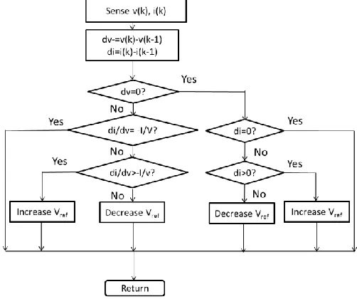
When operating point is varied, method determines in which direction it must perturb the system depending upon the sign of differential conductance. This results in a relationship between PV conductance and incremental conductance. The algorithm is as shown in Fig. 4.The simulation and hardware results are discussed in detail in next section.
Fig.4 Flowchart for Incremental Conductance method [5,6 ]
IV. SIMULATIONANDHARDWARERESULTS
A. Simulation results:
The simulation has been carried out in Matlab Simulink by considering the solar panelof 250 Wp with the specifications as given in Appendix I. The Simulink model of complete system using boost converter is shown in Fig. 5.
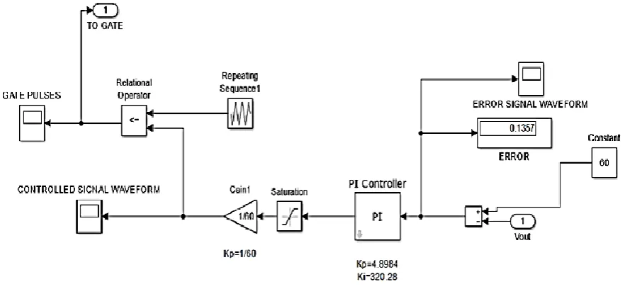
130 The MATLAB Simulink model of closed loop control using PI controller is shown in Fig 6.To obtain the gate switching pulses we have used sinusoidal pulse width modulation technique.The actual output voltage V0of Boost Converter is compared with the reference constant voltage of 60 V. Then the error is passed through a PI controller which reduces the steady state error in the output voltage. This error is limited by using saturation block. At the output of saturation block we get the controlled signal waveform which is then compared with the repeating sequence of the frequency same as switching frequency of boost circuit. Whenever the magnitude of error signal is greater than the magnitude of repeating sequence we get the gate pulses. These gate pulses are given to MOSFET of boost converter.
Fig 6. Simulink Model of close loop PI controller
The inductor current, gate pulses, output voltage and output current waveforms are as shown in the Fig 7, Fig 8 and Fig 9 respectively.
Fig 7Waveform of Inductor Current Fig 8Waveform of Gate pulses
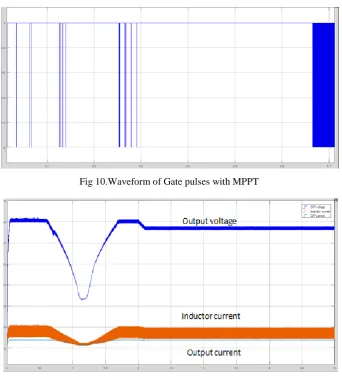
131 For decrease in irradiance from 1000 W/m2 to 250 W/m2for the time duration from t=0.7 s to t=0.17 s, the duty cycle of switching increases and whenever it reach to MPP, the duty cycle remains almost constant to maintain the MPP as shown in Fig 10 and Fig 11 respectively.
Fig 10.Waveform of Gate pulses with MPPT
Fig.11. Inductor current, output current and output voltage waveforms
B. Hardware results:
The Incremental conductance algorithm is implemented using DSP. The code of the implementation is written using C programming. We generate the gate pulses from DSP for an operating frequency of 15 kHz and DSP oscillator frequency 80 kHz. For obtaining square pulses we need to calculate the TBPRD and CMPA i.e. Duty cycle.The TBPRD and CMPA values are calculated as follows:
TBPRD= 𝑂𝑠𝑐𝑖𝑙𝑙𝑎𝑡𝑜𝑟 𝑓𝑟𝑒𝑞𝑢𝑒𝑛𝑐𝑦
2∗𝑜𝑝𝑒𝑟𝑡𝑎𝑡𝑖𝑛𝑓 𝐹𝑟𝑒𝑞𝑢𝑒𝑛𝑐𝑦
= 80∗10𝑒6
2∗15∗𝑒3
= 2666.667
CMPA= (1-Duty cycle)*TBPRD
Assuming duty cycle of 0.5,
CMPA= (1-0.5)*2666.667
= 1333.333
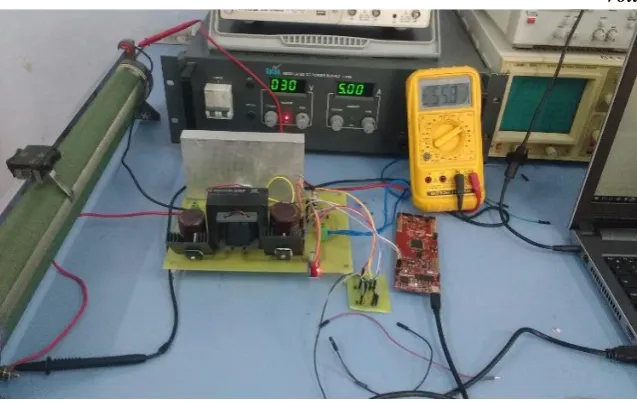
132 Fig 12 Experimental setup with constant DC source
For the input of 30V and 5 A current, the output voltage is boosted to 55.89 V which is almost twice the input voltage which is below 60V due to losses in the circuit. The duty cycle is around 0.5. The sensed values from the solar panel are shown in the window of DSP Fig 13.
Fig 13 Solar panel sensed values obtained from DSP
V. CONCLUSION
Solar energy has a lot of potential to emerge as a reliable and stable source of power in the coming years. In this project, a solar panel of rated output 250Wp at STC is considered for designing the system. Solar panel produces DC power at low voltage, hence design of boost converter is essential. It is modelled, simulated in MATLAB Simulink and implemented in hardware to verify the simulated results. The solar radiation is not predictable and its intensity varies throughout the day. Therefore, to harness maximum power from the source, an MPPT system using Incremental conductance method is implemented to get constant voltage during extraction of maximum power. The power extracted can be delivered to load as well as can be stored in battery for future use.
Appendix I. Specifications of Solar panel at Standard Temperature Conditions [11]
Parameter Specification
Maximum Power 250 Wp
Open circuit voltage 37V
Short circuit current 8.55A
Voltage at maximum power 30.91V
133 REFERENCES
[1] Ministry of New and Renewable Energy, “Solar Mission: Jawaharlal Nehru National Solar Mission”. [2] CEA-India, “Growth of Electricity Sector in India from 1947-2015”.
[3] C.-X. Liu and L.-Q. Liu, “An improved perturbation and observation MPPT method of photovoltaic generate system,” in Proc. IEEE Conf. Ind. Electron. Appl. (ICIEA), 2009, pp. 2966–2970.
[4] F. Iov, M. Ciobotaru, D. Sera, R. Teodorescu, F. Blaabjerg, “Power Electronics and Control of Renewable Energy Systems,” IEEE Trans. On Industrial Electronics, Vol. 55, No. 7, pp.1−27, July. 2007.
[5] Rosa Mastromauro, Marco Liserre, and Antonio Dell‟Aquila, “Control Issues in Single Stage Photovoltaic Systems: MPPT, Current and Voltage Control,” IEEE Trans. On Industrial Informatics, Vol. 8, No. 2, pp.241−254, May. 2012.
[6] D. Sera, “Optimized Maximum Power Point Tracker for Fast-Changing Environmental Conditions,” IEEE Trans. On Industrial Electronics, Vol. 55, 2008, pp. 2629–2637.
[7] Weidong Xiao, Magnus G. J. Lind, William G. Dunford, and Antoine Capel, “Real-Time Identification of Optimal Operating Points in Photovoltaic Power Systems,” IEEE Trans. On Industrial Electronics, Vol. 53, No. 4, pp.1017−1026, Aug. 2006.
[8] Chih-Yu Yang, Chun-Yu Hsieh, Fu-Kuei Feng, and Ke-Horng Chen, “Highly Efficient Analog Maximum Power Point Tracking (AMPPT) in a Photovoltaic System”, IEEE transactions on Circuits and Systems—I: Regular papers, vol. 59, no. 7, July 2012.
[9] L.Umanand and S.R. Bhat, “Design of Magnetic Componenets for switched mode Power Converters”, 1stEdition, 1992,New Age International Publishers Ltd.
[10] Ned Mohan, Tore M. Undeland, William P. Robbins, “Power Electronics: Converters, Applications, and Design”, Wiley; Third edition (16 January 2007).