Available Online at www.ijpret.com
436
INTERNATIONAL JOURNAL OF PURE AND
APPLIED RESEARCH IN ENGINEERING AND
TECHNOLOGY
A PATH FOR HORIZING YOUR INNOVATIVE WORK
ANALYSIS OF EXPANSION JOINT IN HEAT EXCHANGER USING FINITE ELEMENT
ANALYSIS METHOD
GAURAV R. MOHITE1, A. P. EDLABADKAR2
1. PG Student, Department of Mechanical Engineering, Yeshwantrao Chavan College of Engineering, Nagpur, India.
2. Professor, Department of Mechanical Engineering, Yeshwantrao Chavan College of Engineering, Nagpur, India.
Accepted Date: 27/02/2014 ; Published Date: 01/05/2014
\
Abstract: The paper mainly focuses on Finite Element Analysis of Expansion Joint in heat
Exchangers using ANSYS. The main Purpose of Expansion joint is to withstand axial deformation (thermal Expansion) & loads inside a High Pressure heat Exchanger. Hence the design of Expansion joint becomes critical. Heat Exchanger with Expansion bellows are widely used in Oil & gas industries today.
Keywords: Expansion Joint, Heat Exchanger, Design Optimization, FEA Analysis
Corresponding Author: MR. GAURAV R. MOHITE
Access Online On:
www.ijpret.com
How to Cite This Article:
Gaurav Mohite, IJPRET, 2014; Volume 2 (9): 436-449
Available Online at www.ijpret.com
437 INTRODUCTION
The main Purpose of Expansion joint is to withstand axial deformation (thermal Expansion) & loads inside a High Pressure heat Exchanger. Sometimes it becomes an indispensable need to carry regular FEA of Expansion joints subjected to Pressure & temperature loads & Optimize the design for smooth functioning of Heat Exchanger. Design Optimization involves lot of analysis Iterations to be carried so as to come up with final safe design.
During normal operation of Heat Exchanger the Expansion Joint is subjected to following loads
i) Internal Pressure load
ii) Internal Temperature load
iii)Both Internal Pressure & Temperature
The Following analysis is involved in Expansion Bellow design
1. Axial load + Thermal expansion (for spring rate calculation)
2. Differential Thermal Expansion
3. Axial Load + Shell Side Pressure + Differential Thermal Expansion
The Analysis is carried in ANSYS Mechanical APDL.
3. MECHANISM OF EXPANSION JOINT:
An expansion joint in a heat exchanger is a specially designed component of compact dimension that allows differential moment between two adjacent components and maintains the pressure envelope. Heat exchangers are always equipped with the hot or cold fluid flowing inside the tubes hence therefore the design of expansion joint plays vital role in maintaining the pressure envelope. The design of expansion joint includes a half symmetry axisymmetric 2D solid model of the flexible sheet element used for the analysis. All thicknesses are considered in minimum thickness condition.
4. DESIGNOF THE EXPANSION JOINT:
Available Online at www.ijpret.com
438 Figure 1- Design Drawing of Expansion joint
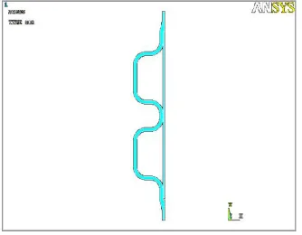
Design of expansion joint using ANSYS Mechanical package is as shown in figure 2.
Figure 2- Design of Expansion Joint using ANSYS Mechanical Package
5. ANALYSIS:-
The analysis is carried out for three load cases.
1. Axial load + Thermal expansion (for spring rate calculation)
2. Differential Thermal Expansion
Available Online at www.ijpret.com
439 The thermo-mechanical analysis is carried out in two steps.
STEP-1 - Thermal analysis is done in which thermal boundary conditions are applied to find out temperature distribution during operating condition of the expansion bellow.
STEP-2 - Second Step is structural analysis in which, side pressures are applied along with the temperature distribution obtained from STEP-1. By applying this temperature, the effect of differential thermal expansion is taken in to account.
6. PROCEDURE FOR DESIGN AND ANALYSIS:-
Following procedure is to be carried out for design and analysis of expansion to obtain the desired result.
6.1. Model Description
A half symmetry axisymmetric 2D solid model of the flexible sheet element is used for the analysis.
All thicknesses are considered in minimum thickness condition without corrosion.
Shell length considered is 400 mm.
Nozzles and other details on shell/channel are not modeled.
Elements used in the analysis:
a) Structure Elements: Solid 183
b) Thermal Elements: Solid 77
Number of elements across thickness in the model
a) Across shell 5
b) Across FSE 6
6.2. Analysis Procedure Details
Component Expansion Bellow
Available Online at www.ijpret.com
440 Analysis type Thermo – Mechanical
Element type Solid Elements
6.3. Design Data
Design code ASME 2007 Ed., Add 2009 (Section I for Shell Side, Sec VIII -Div 1 for Tube Side)
Internal Design Pressure, Pi “0.17329kg/mm2” (Shell Side)
Design Temperature Shell side in 3150 C, Ambient Temperature (External) 480 C
Corrosion allowance 3 mm (shell side)
6.4. Material Data
Material Properties has been taken from ASME Sec II Part D
Mechanical & Thermal properties of Material Used for Various Components
Expansion bellow and shell-
Material- SA 516 Gr 70
Design temperature- 3150 C
Modulus of elasticity- 18632 Kg/mm2
Allowable design stress at design temperature- 13.614 Kg/mm2
Thermal Conductivity - 4.3W/mC
Coefficient of thermal expansion- 1.332E-05 /C
6.5. Units
a) Force – kg
b) Pressure – kg/mm2
c) Length – mm
6.6. Load Cases
Available Online at www.ijpret.com
441 6.6.2 Mechanical loading and boundary conditions
a) Load case 1 – Axial Load + Thermal Expansion (for spring rate calculation)
b) Differential Thermal Expansion
c) Load case 2- Axial Load + Shell Side pressure + Differential Thermal Expansion
Shell side pressure = 0.17329 kg/mm2
Temperature Distribution obtained from 6.6.1 above
6.7. Boundary conditions and loads
6.7.1. Design internal pressure on Shell side.
6.7.2. Bellow end is constrained in axial direction.
6.7.3. Pressure Thrust on Shell (small diameter) end.
6.7.4. Temperature distribution from thermal load case.
6.7.5. Calculation of axial thrust on Shell
Axial Pressure Thrust at Shell End = Pi*Di2/ (Do2 - Di2) = 2.773296 kg/mm2
Pi = 0.17329 kg/mm2
Do = OD of Shell = 670mm
Di = ID of Shell = 650mm
6.8. Thermal boundary conditions
6.8.1. Convective Heat Transfer Coefficients & Temperatures On shell side-
Convective heat transfer coefficient-0.063426 kgf-mm/S/C, Temperature- 160
Between Sleeve Plate and Expansion Bellow-
Convective heat transfer coefficient-0.010275 kgf-mm/S/C, Temperature- 160
Available Online at www.ijpret.com
442 Shell side temperature is found out from separate thermal analysis using above boundary conditions in ANSYS Mechanical APDL 13.0
6.9. Geometry Model
Solid Model Plot IN ANSYS
6.10. FE Model
Meshed model in ANSYS
6.11. Boundary Conditions and Loads
Boundary conditions and loads applied as follows
6.11.1. Thermal Boundary Condition
Available Online at www.ijpret.com
443 6.11.2. Mechanical Boundary Condition and Loads
Load case 1 – Axial Load + Thermal Expansion (for spring rate calculation)
The model is restrained axially in the symmetric location.
Shell length considered for t his analysis is 1430 mm.
Axial load applied – 57502.9462 kg
Axial Pressure Thrust load at Shell End = Pi* π *Di2/4 = 57502.9462 kg
Pi = 0.17329 kg/mm2
Di = ID of Shell = 650mm
Load case 2- Differential Thermal Expansion
Available Online at www.ijpret.com
444 Load case 3- Axial Load + Shell Side pressure + Differential Thermal Expansion
The model is restrained axially in the symmetric location. The pressure applied on the shell side. The pressure applied on the shell side is 0.17329 kg/mm2. Axial load from load case 1 and load case 2 is applied at the small diameter end. It also takes the thermal expansion effects.
6.11.3. Mechanical Boundary Condition and Loads
Load case 1–Axial Load + Thermal Expansion (for spring rate calculation)
The model is restrained axially in the symmetric location. Shell length considered for this analysis is 1430mm.
Axial load applied – 58569.44 kg
Axial Pressure Thrust load at shell end = Pi* π *Di2/4 =58569.44 kg
Pi = 0.17329 kg/mm2
Available Online at www.ijpret.com
445 Load case 2- Differential Thermal Expansion
This load step calculates the axial load due to differential thermal expansion. Only symmetric half of the Flexible Shell Element is modeled. The model is restrained axially in the symmetric location. Temperature is applied on the model from the thermal analysis. No pressure loads are applied. At the FSE end an axial displacement of 0.06325mm is applied in the negative Y direction.
Load case 3- Axial Load + Shell Side pressure + Differential Thermal Expansion
The model is restrained axially in the symmetric location. The pressure applied on the shell side is 0.17329 kg/mm2. Axial load from load case 1 and load case 2 is applied at the small diameter end. It also takes the thermal expansion effects.
6.12. Results
Various results plotted for the following with obtained result and calculations (as shown in figures)
Available Online at www.ijpret.com
446 Axial Pressure Thrust at Shell End = Pi* π *Di2/4 = 57502.9462 kg
Pi = 0.17329 kg/mm2
Di = ID of Shell = 650 mm
Axial stiffness of Expansion Bellow = 3778.38 kg/mm
6.12.2. Temperature Distribution from Thermal Analysis (Unit 0C)
6.12.3. Deformation Plots for Load Case -1 (Unit-mm)
Available Online at www.ijpret.com
447 Zoomed view
6.13. CONCLUSION
The Expansion bellow is being analyzed both for thermal and mechanical loading. If induced stresses are lower than the allowable limits for all conditions, the design passes the criteria.
7. LITERATURE SURVEY: -
In the field of Heat Exchangers it is important to know the type of fluid and its properties for which the Heat Exchanger is to be designed. Since different fluid requires different arrangement of tubes therefore the design of expansion joint also gets affected and frequent design and analysis procedure is to be carried out over it.
J.A Dreister[1] provides modern achievements to be considered in the field of heat transfer in tubular heat exchangers. The requirements are to stated to be met by highly efficient tubular heat exchange surface. It is shown that it is quite possible to make tubular heat exchangers more compact than the plate ones. A critical analysis of the up-to-date methods for evaluation of the efficiency of heat transfer enhancement in channels is presented.
Available Online at www.ijpret.com
448 Delvonei Alves de Andrade, Gabriel Angelo, Gerson Fainer and Edvaldo Angelo [3] worked on IEA-R1 heat exchanger. IEA-R1 heat exchanger is of the type shell-and-tube, STHE, with one-pass shell and one-one-pass tube in countercurrent flow. Its total length is 7 meters. It was commissioned in 2009.
Qi-Wu Dong and Min-Shan Liu [4] suggested that in recent years fatigue fracture and wear damage caused by flow-induced vibration have been common occurrences. In order to improve the safety and stability of heat exchangers, mechanism of vibration in heat exchangers are studied and anti vibration criterion and measures are presented for the design of heat exchangers in the paper.
Y. A. Khulief, S. A. Al-Kaabi, S. A. Said, M. Anis [5] worked on Flow-induced vibrations due to cross flow in the shell side of heat exchangers pose a problem of major interest to researchers and practicing engineers. Tube array vibrations may lead to tube failure due to fretting wear and fatigue. Such failures have resulted in numerous plant shutdowns, which are often very costly. The need for accurate prediction of vibration and wear of heat exchangers in service has placed greater emphasis on the improved modeling of the associated phenomenon of flow-induced vibrations.
K. C. Leong, K. C. Toh, Y.C. Leong [6] gives information in their paper about a software for the thermal and hydraulic design of shell and tube heat exchangers with flow induced vibration checks has been developed in a Windows-based Delphi programming environment. Its user-friendly input format and excellent colour graphics features make it an excellent tool for the teaching, learning and preliminary design of shell and tube heat exchangers. Design methodology is based on the open literature Delaware method while flow-induced vibration calculations adhere closely to the methodology prescribed by the latest TEMA standards for industry practice.
8. REFERENCES
1. J. A Dreister, ‘’Problems in Developing Highly Efficient Tubular Heat Exchanger’’, ISSN 0040-6015 vol 53 no.4
2. J. A. Guirao, Silvia Iglesias, Benéitez and S.L. J. PistonoIn, Research on ‘’New Method for Optimized Design of Heat Exchangers’’
Available Online at www.ijpret.com
449 4. Qi-Wu Dong and Min-Shan Liu, ‘’Anti vibration Design of Tubular Heat Exchangers’’, Journal of Pressurized Equipment and Systems 2 (2004) 21-24
5. Y. A. Khulief, S. A. Al-Kaabi, S. A. Said, M. Anis, ‘’Prediction of Flow-Induced Vibrations in Tubular Heat Exchangers—Part I: Numerical modeling’’, Journal of Pressure Vessel Technology Copyright © 2009 by ASME FEBRUARY 2009, Vol. 131 / 011301-1
6. K. C. Leong, K. C. Toh, Y.C. Leong, “Shell and Tube Heat Exchanger Design Software for Educational Applications” , International Journal Engng Ed. Vol. 14, No. 3, p. 217-224, 1998