Improving the Efficiency of an I.C. Engine by Using Secondary
Fuel (HHO)
Dr. V.V. Prathibha Bharathi
1I. Parameshwara Rao
2V.V.Naga deepthi
3I. Prasanna
4A. Lakshmi Jyothi
51 Head of Mechanical Department Mallareddy college of engineering 2,3,4,5 Assistant professor in Mechanical Department
INTRODUCTION
Energy is the primary and most universal measure of all kinds of work by human beings and nature. Everything that happens in the world is the expression of flow of energy in one o fits forms. Energy is an important input in all sectors of a country’s economy. The standard of living is directly related to per capita energy consumption (Vader and Joshi, 2005). Conventional energy sources based on oil, coal, and natural gas have proven to be highly effective drivers of economic progress, but at the same time damaging to the environment and to human health. Furthermo re, they tend to be cyclicalin nature, due to the effects of oligopoly in production and distribution. These traditional fossil fuelbased energy sources are facing increasing pressure on a host of environmental fronts, w i t h perhaps the most serious challenge confronting the future use of coal being the Kyoto Protocol greenhouse gas reduction targets (Herzogetal, 2006). Spark ignition (SI) and compression ignition(CI) engines are commonly used for transportation. Fossil fuels used as energy resources for internal combustion engines (ICEs) are known as “ automotive fuels” (gasoline, diesel fuel, liquefied petroleum gas (LPG), natural gas). Gasoline i s always used in SI engines, with a current maximum compression ratio of eleven. A thigher ratios, the mixture in the combustion chamber ignites spontaneously, causing e n g i n e knock, which may lead to severe engine damage. Very recently, gasoline has come into consideration as a hydrogen carrier for fuel cell vehicles. Diesel (diesel oil) burns in CI engines. Pure LPG can function only in SI engines a gasoline engine retro fitted for dual fuel use, a dedicated gas engine or a heavy- duty diesel engine retro fitted with a SI system.
EXPERIMENTATI ON ENGINE DETAILS
All automobile engines are categorized into its CC. For example an engine has single cylinder is 100CC. 1000 CC is equal to one litre. The HHO requirements also depend upon the level of engine CC and other devices. Approximately 100 CC engine requires 0.05 litre of HHO per minute.
BASIC DETAILS FOR HHO:
As said before, the HHO generator involves in the production of hydrogen and oxygen with a help of process of electrolysis. In this process, Direct Current is passed through electrodes to water, due to chemical reaction, the positive plates generate Oxygen and negative plates generate Hydrogen. Pure water does not conduct
EXPERIMTAL SET UP
COMPONENTSThe following are the components
•
HHO kit, Catalyst (baking soda), Hero Honda passion pro bike, Tools, Distilled water, Petrol testing meter
HHO-KIT:-Electrolyzing chamber, Moisture filter, HHO transfer hoses, Injection nozzle, Plastic bottle, Camp
ELECTROLYZING CHAMBER:-
It is made up of titanium dioxide which is from of metal oxide .It separates pure gases using and oxygen gases using DC amps. At the top of electrolyzing water feed nozzle is placed .It is used to feed the water into the electrolyzing chamber .The DC current is taken through the wires connected from the pulse dozer which supplies the current. The wires are connected to the cathode and anode securely inside the electrolyzing chamber .It is nearly 10mm diameter opening into the chamber
Electrolyzingchamber
MOISTUREFILTER:
It is used to filter the moisture particles in the hydrogen gas produced in the electrolyze chamber .It is main function is to prevent entering these moisture particles into the engine
Moisturefilter
HHO TRANSFER HOSES:
HHO transferhouse
INJECTIONNOZZLE:
It is like a passage for the hydrogen gas to enter into engine .It is like acylindrical shaped pipe leak proof caps and it is connector one of its sides is connected to theconnecting hose in which the hydrogen gas is passing another end is connected into the air filter bootof thevehicle.
Injectionnozzl
PLASTICBOTTLE:
It is tube shaped small size bottle narrowed at its top and a cap having along opening. It is used to mix the electrolyte and the distilled water thoroughly .Later top is cutto feed the water into theelectrolyze
CLAMP:
It is used for the purpose of holding the electrolyze to the safety rod of thevehicle very tightly by using bolt and nut .It is made ofsteel.
PlasticClamp
BAJAJ CT-100 BIKE:
Theengineis97.2ccair–cooled,four–strokesinglecylinder.Thechassisisa tubular double cradle type .Bajaj CT-100 millage is 85-90 kmph. Its transmission is4-speed constantmeshgear.Ittyreshasdrumtypebrakes.Itsfuelcapacityis12.8liters(1.1liters reserve)
Assembly of HHO kit Bajaj CT -100BIKE
TOOLS:
The tools used in this in this projectare:
DISTILLEDWATER:
Distilled water is water that has many of its impurities removed through distillation involves boiling the water and then condensing the steam into a clean container. The distilled water is necessary because if we use generally available water then the impurities will clog up the electroes of HHO generator and further impede the operations of the HHO celloverall. ItisthattheseimpuritiesaccompanyknowngaseswhichmixwiththeHHOgastogoonto create unknown chemical reactions which are toxic to the environment .The distilledwater should be changed for periodical interval of every 5000-7000k Therefore only distilledwater should be used in the production of HHO gas from any type of HHOgenerator.
Fig 5.11: Distilledwater
PETROL TESTINGMETER:
It is the test equipment used to measure the quantity of fuel while conducting the test. It is in the shape of flask having avalveatits bottom. This valve is connected with a hose who seo the rend is connected to the inletofcarburetor. The opening of this valve allows the fuel to enter into the carburetor. This opening can be adjusted to the required rate offlow of fuel into the carburetor. It has readings marked on it. This facilitates in knowingthe quantity of fuel used in performing thetest.
Petrol testingmeter
INSTALLIATIONPROCEDURE
ELECTROLYSERINSTALLATION:
Firstremovethesafetycoverfromtheelectrolyzer.Connectthefittingclampand adjust the clamp according to the requirement. First position the vehicle in rest conditionby putting it in Centre stand. Fix the electrolyzer to safety rod in vertical position. Whilefixing the clamp fix it tightly by using cutting pliers. Adjust the fitting as per ourrequirement. After adjusting tighten the nut and bold rigidly. While fixing the electrolyzer check the position of the electrolyzer on the safety rod. Make sure that the electrolyzer is not shaking.
CONTROLLER INSTALLATION:
connect all wires safely. Now start the vehicle to check the lighting circuit. When lighting circuit is disconnected you can see the head light off. By doing this test we can ensure that the connection is correct. Check the voltage in wire using multimeter. Select the alternator selection in multimeter since the dynamo output is alternator supply. Check the voltage available in the socket separately. The wire which has more voltage is taken as correct wire. Here white wire gets more voltage. Hence it is taken as correct wire.
Now the second level of testing starts. When we increase acceleration, the voltage will also increase. While performing this test ensure that the white wire is connected with yellow wire. After ensuring the correct connection the sub socket is to be connected with the main socket. The positive connection is given on the right side cover of the vehicle. Red color wire is to be connected with the brake wire. Switch output is connected within circuit of the socket To check the correctable, disconnect the socket and then check the voltage by using multi meter by selecting the DC option ground to brake line voltage. Brake line supply will work only when you switch on the key. Hence switch on the key and then measure the voltage.
HOSECONNECTION:
The hose is the passage for the HHO gas to enter into the air intake of t h e engine. To filter the gas produced, afilterelementisusedin between its flow to the engine air intake. The filter element should be connected by facing the electrolyzer and fire arrestor should be facing air filter. The injection of HHO gas into the air intakepipe should be in such a way that it should mix with the oxygen in its way. According to required length the hose is to be connected. Injection nozzle should be connected at the air intake facing towards the air intake carburetor. To connect the injection nozzle make a small hole into the air filter boot by using screw driver. After ensuring the correct connectivity, apply the glue on its neck to prevent the leakage. Now the HHO systemis ready towork.
PREPARATION OFELECTROLYTE:
The catalyst used to produce oxy hydrogen gas (HHO) is Potassium hydroxide (KOH). Mix this catalyst with the distilled water in the plastic bottle. Shake it properly and check whether it is mixed completely or not. This mixing should bedone properly in the plastic bottle. After mixing, cut the top of the bottle and then fill the water and feed it into the electrolyzer through the water feed nozzle. It should not exceed the limit above the electrolyzer
TESTING:
After filling the water in the electrolyzer start the engine.
After starting, check the voltage and current by using multi meter.
DC amperes can be between 1.2 to1.3 DC voltage can be between 6.2 to6.5
INSTALLATIONCOMPLETE:
Working of electrolyzer can been sured by seeing the oxy hydrogen bubbles in the electrolyzer. Now the vehicle is ready to drive.
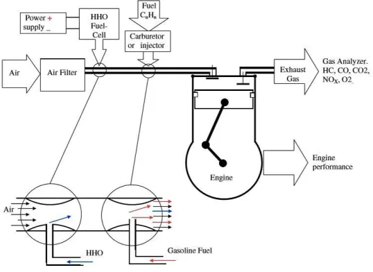
WORKINGPRINCIPLE
After installing electrolyzing chamber to safety rod of bike the engine is started. Then the pulse dozer generates 12V-13V in it. But it supplies only 3V-4V to the electrolyzing chamber. When the current is supplied, the electrolys is process starts in the electrolyzing chamber. There action stake place between the anode and cathode. This will dissolve H2O into 2 parts Hydrogen and 1part Oxygen and combing this two generates oxy hydrogen (HHO) gas inside the electrolyzer.
and energy is produced. This energy produce dis greater than the energy produced when only petrol and air is combusted in the enginecylinder.
TEST
Fig 5.13: Basic layout ofHHO
Here in this project we are going to conduct two types of test to ensurethe advantage gained on using this innovativetechnique.
MILEAGE TESTING:-
Mileage is nothing but the fuel economy of any automobile. It is the totaldistance travelled by the automobile for specified quantity of fuel. For example BAJAJCT100 (petrol) bike gives the mileage of 80 kmpl. So our project aims to increase this mileage compared with vehicle running without this equipment.
FIRSTSTEP:
•
Before installing the equipment run the vehicle with 1 litre fuel either petrol ordiesel.•
Note down the distance (kms) travelled by the vehicle in complete 1 litrefuel.SECONDSTEP:
•
Now install the equipment to the vehicle and run it with1 litre fuel.•
Note down the distance (kms) travelled by the vehicle in complete 1 litre fuel.•
Make minimum three trail runs and note thereadings.THIRDSTEP:
•
Tabulate the readings obtained in the above twosteps.•
Take the difference of these readings and note the resultedvalue.•
This would be extra mileage added to the vehicle on using thistechnique.EMMISIONTEST:
Due to the combustion of fuels in the vehicle some gases (exhaust gases) areproduced such as hydrocarbons, carbon monoxide (CO), nitrogen oxides (NOx), sulphur oxide etc,.
This is called emission of gases in automobile. We know that these gases are one of the reasons for global warming. So our project aims to reduce these harmful emission with the help this new technique.
FIRSTSTEP:
Make a trail run with one litre petrol/diesel.
Check the emission at mobile pollution checkvehicle.
As the pollution check certificate has validity up to 6 months of period it canbe conformed for the next two moretrails.
SECONDSTEP:
After installing the equipment make a trail run with one litre petrol/diesel.
Check the emission at mobile pollution check vehicle.
As the pollution check certificate has validity up to 6 months of period it canbe conformed for the next two moretrails
THIRDSTEP:
Tabulate the readings obtained in the above twosteps.
Take the difference of these readings and note the resultedvalue.
Next convert the resulted value into percentage.
This would be the percentage of reduced emission obtained by usingthis technique
RESULTS
RESULT OF MILEAGETEST:
SLNO By usingpetrol By usingPetrol+HHO
1 80 90.5
2 79 92.8
3 79 94
Table 5.2 – Result Of MileageTest
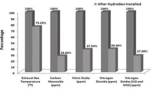
RESULT OF EMISSIONTEST:
Fig 5.14: HHO Performance in emissiontest
ADVANTAGES:
Increases millage up to20%-40%.
ReducesEmission.
Increases Pick- uppower.
Complete combustion of fuel upto98%Reduces Engine noise & vibration.
No need of R.T.O approval.
Easy toinstall.
Increases life of engine &battery.
DISADVANTAGES:
•
Initial cost is high.•
One of the main limitations of HHO based automobile is that it takes about5 minutes for the production of HHO gas.•
Anotherlimitationofthistypeofproductionofgasisthewaterusedinthistype of production should be very pure without any contaminants.•
APPLICATIONS
It is used in both S.I. Engines and C.I.Engines.
It is used in both 2-wheelers and4-wheelers.
Thiskitisoneofthepollutioncontroldeviceusedtocontrolthepollutionin automobiles.
HHO is used instead of traditional fuels like petrol, dieselgasoline…etc.
CONCLUSIONS
Our project is to obtain advancement in the field of automobile. For that reason we made combustion in vehicles using HHO gas. It resulted in the increase of mileage up to 20% and also reducing the emission of harmful gases up to 60%. This technique acts as a source to decrease money towards vehicle fuelling and also it makes us a part in the contribution made in reducing the global warming.
THE FOLLOWING CONCLUSIONS ARE OBSERVED AS FOLLOWS
The use of HHO in gasoline engines combustion efficiencies consequently fuel consumption by20%.
Use of HHO in gasoline engines leads to emission of harmful pollutants such as monoxide and un burnt hydrocarbons.
Use of HHO in gasoline engine increases the output of the engine around 5.7%. The HHO gas kit can be easily constructed and integrated with existing engines at low cost.
REFERENCES
[1]. Apostolescu, N., Chiriac, R., “A Study of Combustion of Hydrogen-EnrichedGasoline in a Spark Ignition
Engine,” Publication #960603, February, 1996,Society of Automotive Engineers, Troy,MI.
[2]. Conte, E., Boulouchos, K., “Influence of Hydrogen-Rich-Gas AdditiononCombustion, Pollutant
Formation and Efficiency of an IC-SI Engine,”Publication #2004-01-0972, March, 2004, Society of
Automotive Engineers, Troy,MI.
[3]. Fontana, G., Galloni, E., Jannelli, E., Minutillo, M., “Performance and FuelConsumption Estimation
of a Hydrogen Enriched Gasoline Engine at Part-LoadOperation,” Publication #2002-01-2196, July,