Using Modular Pole for Multi-Objective Design Optimization
of a Linear Permanent Magnet Synchronous Motor by
Particle Swarm Optimization (PSO)
C. Lucas*, Z. Nasiri-Gheidari** and F. Tootoonchian***
Abstract: In this paper particle swarm optimization (PSO) is used for a design optimization of a linear permanent magnet synchronous motor (LPMSM) considering ultra low thrust force ripples, low magnet consumption, improved efficiency and thrust. The influence of PM material is discussed, too and the modular poles are proposed to achieve the best characteristic. PM dimensions and material, air gap and motor width are chosen as design variables. Finally 2-D finite element analyses validate the optimization results.
Keywords: Particle Swarm Optimization (PSO), Linear Permanent Magnet Synchronous Motor, Optimization, Modular Poles, Finite-Element Analysis.
1 Introduction1
Slot less permanent magnet linear synchronous motor (PMLSM) has many advantages. So, it is widely used in variety of industrial applications. It does not generate detent force. So, it has not only low thrust ripple but also low normal force [1]. And because it has no iron core, its iron loss is negligible and it has fast dynamic [2]. But in the precise applications, it is important to eliminate even low ripples by optimal design or control strategies. On the other hand excessive use of permanent-magnet materials lead to undesirable performance and a wrong selection of PM material lead to high production cost [1-3].
There is much work on the design and optimization of linear synchronous motors has been reported in [4-8]. Such optimization of the LSMs has been performed based on different objective functions.
In [1], power density increases with a method of inserting core between windings of each phase of the slotless PMLSM model. In this method by inserting a core, detent force is generated due to dispersion of air-gap magnetic reluctance. Thrust ripples are generated due to that detent force. Therefore, [1] has proposed the
Iranian Journal of Electrical & Electronic Engineering, 2010. Paper first received 4 Apr. 2010 and in revised form 2 Oct. 2010. * The Author is with the Center of Excellence, Control and Intelligent Processing, Faculty of Electrical and Computer Engineering, University of Tehran, Tehran, Iran.
E-mail: [email protected]
** The Author is with the Department of Electrical and Computer Engineering, University of Tehran, Tehran, Iran.
E-mail: [email protected]
*** The Author is with the Department of Electrical Engineering, K. N. Toosi University of Technology, Tehran, Iran.
E-mail: [email protected].
method of dividing permanent magnet (PM) in order to reduce the higher harmonics of the magnetic flux, and consequently, the ripples in the thrust. In [4] a two-dimensional finite-element analysis is used to predict detent force and thrust due to structural factors and nonlinearity of iron core LSM. In this paper moving node techniques for the drawing models is used to reduce modeling time and efforts. An optimum design of LPMSM with considering low thrust pulsation is discussed in [2]. This reference uses the genetic algorithm for searching optimal dimensions. A substantial reduction of force pulsations in air cored LPMS motors is the focus of design optimization in this paper. In [9] an optimal design of permanent magnet disc motor using GA as an optimization tool is performed and the efficiency of the motor are selected as an objective function of the optimization. Although some papers presents the optimized arrangement of the permanent magnets to reduce thrust ripples, there are some publications which use control strategies to avoid force ripple. In [10] a neuronal-network based feed forward controller is proposed to reduce the effect of force ripple. In [11-12] a model based approach for the limitation of the force ripple is proposed, because force ripple is a highly reproducible and time-invariant disturbance. The force ripple model is based on a Fourier series approximation and is identified by measuring the control signal in a closed position control loop for different load forces. Ref. [11] presents a method of optimal design for minimization of force ripple and maximization of thrust force in linear brushless permanent magnet motor without Finite Element Analysis. But in this paper the volume of
permanent magnet and efficiency is ignored. In [13] modular poles are used for shape optimization of flux density distribution in permanent magnet machines and in [3] a multi-objective optimization is presented based on Genetic algorithm. Thrust mean, thrust ripple and magnet volume are chosen as objective functions.
In this paper thrust mean, thrust ripple, magnet volume, and efficiency of a LPMSM are optimized. Motor length, air gap, magnet dimensions, and material are chosen as design variables. A modular poles configuration is decided in this paper which reduced the cost of permanent magnet. In this configuration central PM is chosen from a stronger permanent magnet than the lateral ones. A flexible objective function is defined including thrust mean, thrust ripple, and efficiency. A multi-objective optimization is then carried out by particle swarm optimization (PSO) to find out the best set of design variables. Since an increase in thrust may result an increase in PM volumes and it can lead to the magnet consumption and high product cost, the ratio of thrust per volume (thrust density) is considered, too. Finally, finite-element method (FEM) is used to verify the optimization results.
2 Structure of Modular Pole
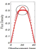
The flux density distribution of a conventional pole with one PM material is depicted in Fig. 1. The solid line shows the fundamental harmonic component of flux density and circles show the real flux density. It is seen that there is a flat region at the top of the real flux density distribution which results in more harmonics in the flux density distribution and non-optimal performance of the electric machine. It seems that using a stronger permanent magnet to produce a stronger magnetic field in the middle of the pole may form a more sinusoidal flux density distribution. To follow this proposal, the MPMP and its design optimization are presented. The proposed MPMPs consist of three or more PM pieces (as modules), with the same height, and different or equal widths, attached together. As so, a MPMP has the same height as the height of a permanent-magnet piece, but a width equal to the sum of widths of all PM pieces forming the pole [13].
Figure 2 shows a modular PM pole. The pole is made of two different permanent-magnet materials. The outside permanent-magnet modules are made of a lower quality permanent-magnet material with a weaker magnetization, while the middle permanent magnet module is made of a higher quality permanent-magnet material with a stronger magnetization. If all PM materials are of rare-earth type, such as Nd-B-Fe with linear characteristic, there would be no danger of demagnetization of lower quality magnets [13].
3 Machine Modeling With Maxwell Equations In order to determine the flux density distribution of a MPMP, it is disassembled into three virtual pieces of
Fig. 1 Flux density distribution of a conventional PM pole.
Solid line: fundamental harmonic component. Circles: total flux density [13].
Fig. 2 Proposed modular PM pole with different material
quality [13].
magnet, as shown in Fig. 2. Flux density distribution produced by each magnet piece is then calculated separately [13].
In machine modeling with Maxwell equations, the permanent magnet synchronous machine is divided to several layers such as: back iron, magnet, air, coils and yoke. Solving Laplace and Poisson equations in each layer gives flux density (B) and field intensity (H) in each point [6].
A physical and layer model of Air cored LPMS motor is shown Fig. 3 and 4 [2,9]. The model consists of two iron layers extended to infinity, two permanent magnet layers and a large air layer, representing the back irons, PM poles and the air gaps plus the primary windings, respectively. In proposed model, the effect of teeth have ignored because there is not any primary iron core with teeth and slots. Magnet layer are shown by current layer. The density of this current will be [2]:
⎟ ⎠ ⎞ ⎜ ⎝ ⎛ τ π ⎟ ⎠ ⎞ ⎜ ⎝ ⎛η π μ π = ∑ = x n Sin 2 n Sin B 4 ) x ( J M r .. . , 3 , 1 n M (1) where τ =
η Wm (the ratio of the magnet width to pole pitch) and x axis is placed in the middle of the magnets. Maxwell equations in the different layers of the physical model are derived. The equations lead to Laplace and Poisson equations as follows [2]:
⎪ ⎪ ⎩ ⎪ ⎪ ⎨ ⎧ = ∂ ∂ + ∂ ∂ μ − = ∂ ∂ + ∂ ∂ II Layer 0 y ) y , x ( A x ) y , x ( A I Layer ) x ( J y ) y , x ( A x ) y , x ( A 2 2 2 2 M 0 2 2 2 2 (2)
where μM is the permeability of the magnet and JM(x) is the PM equivalent current density, which is given by equation (1).
Also, Br is the magnetic flux density. The boundary conditions of these equations are [2]:
⎪ ⎩ ⎪ ⎨ ⎧ = − = = = = = = 0 H h y B B and H H 0 y 0 H g y xII M yII yI xII xI xI (3)
The corresponding general solutions of Eq. (2) are [2]:
I
n y n y
r r
1 2
n 1, 3,... A (x)
n x
C e C e Sin
π π π
τ ∞ − = = ⎛ + ⎞ ⎛ ⎞ ⎜ ⎟ ⎜ ⎟ ⎝ ⎠ ⎝ ⎠
∑
(4)II
n y n y
r
r r
3 4 2 2
n 1, 3,... A (x)
4B n n x
C e C e Sin Sin
n
π π τ η π π
π τ τ
∞ − = = ⎛ + + ⎛ ⎞⎞ ⎛ ⎞ ⎜ ⎜⎝ ⎟⎠⎟ ⎜⎝ ⎟⎠ ⎝ ⎠
∑
(5)The permeability of the back iron is supposed to be infinity. Considering those conditions the constants of Eqs. (4) and (5) can be found as follows [2]:
M M M M 2n g 1 2 2 r 2 2
2n g 2n h
M 2n g 2n h 0 2n h 3 4 2n g M
4 2n h 2
C C e
C
4B n
Sin
n 2
e 1 e 1
e 1
e 1
C C e
e 1 C C e 1 π τ π π τ τ π τ π τ π τ π τ π τ
τ η π
π μ μ μ − − − − = = ⎛ ⎞ ⎜ ⎟ ⎝ ⎠ ⎛ ⎛− + ⎞⎛ + ⎞⎞ ⎜ ⎜ ⎟⎜ ⎟⎟ ⎛ + ⎞⎜ ⎝ ⎠⎝ ⎠⎟ ⎜ ⎟⎜ ⎛ ⎞ ⎟ ⎝ ⎠ − ⎜ ⎟ ⎜ ⎝ ⎠ ⎟ ⎝ ⎠ = ⎛− + ⎞ ⎜ ⎟ ⎝ ⎠ = ⎛ − ⎞ ⎜ ⎟
⎝ ⎠ (6)
The flux density can be obtained by the curl of the magnetic vector potential. As the direction of the magnetic vector potential is normal to the x–y plane, the flux density distribution is [2]:
j x A i y A A
Br r r r
∂ ∂ + ∂ ∂ = × ∇ = (7)
Therefore, the flux density in middle of the magnetic air gap has only a normal component given by [2]:
y
n g n g
1 2
n 1,3,... A B (x)
x
n n x
C e C e Cos
π π τ τ π π τ τ ∞ − = ∂ = − = ∂ ⎛⎛ ⎞ ⎛ ⎞⎞ − ⎜⎜ + ⎟ ⎜ ⎟⎟ ⎝ ⎠ ⎝ ⎠ ⎝ ⎠
∑
(8)Since the magnetic air gap is large, saturation has not occurred and all materials behave linearly.
Fig. 3 Schematic view of a double sided air-core LPMS motor
[3]. ∞ = μ ∞ = μ II. Magnet II. Magnet I. Air hM hM g X Y
Fig. 4 A layer model of an air core LPMS motor [2].
Therefore, the normal component of the resultant air gap flux density is obtained by using the superposition theorem as [13]:
∑
=
= n
1
i yi
y(x) B (x)
B (9)
where Byi is the normal components of flux density due to ith permanent magnet.
From Eq. (9), the fundamental component of the PM field, as well as its harmonics, can be obtained. Therefore, the maximum value of the PM flux under each pole is obtained as [2]:
L B 2
lg
PM = π τ
ϕ (10)
where Blg is the fundamental component of the PM flux density. According to a conventional electrical d–q model of the machine in a synchronously rotating reference frame the motor force is obtained as [2]:
(
)
[
PM d q d]
qav 23 L L i .i
F λ + −
τ π
= (11)
A surface PM type motor with rare earth PM poles having relative permeability close to unity is used in which saturation rarely occurs; thus, Ld ≈Lq . As a result, by ignoring very low reluctance thrust, (11) is simplified to [3]
q PM av 23 i
F λ
τ π
= (12)
If the coil dimensions and current density are known, (12) can be represented by [3]
P J A 2
3
Fav = πτϕPM s rms (13)
where As and Jrms stand for coil area per pole per phase, effective current density, and pole pairs, respectively. Also, φPM stands for flux per pole given by (10).
In this kind of motor, iron loss is negligible due to lack of iron in moving part and large effective air gap. Therefore, the essential part of electrical loss is the copper loss expressed as [3]
(
L l)P
A J 6 I R 3Pcu 1 2 cu 2 s e
rms
rms = ρ +
= (14)
where R1, ρcu and le are phase winding resistance, resistivity of copper, and the length of end connection, respectively. Also, there are additional losses (Padd=0.03Pout), including mechanical loss and stray loss. Therefore, motor efficiency is given by [3]
add cu out
out
P P P
P
+ + =
η (15)
where Pout=Fav.vs and vs is the synchronous speed [11].
4 Optimization
4.1 Objective Function Selection
In this paper a multi-objective optimization problem is discussed. Design variables are motor length, air gap and magnet dimensions (magnet height and magnet width). On the other hand maximization of thrust mean and efficiency and minimization of thrust ripple and magnet volume are chosen as objective functions.
It seems that by minimizing the total harmonic distortion (THD) of Bg as an objective function, the force pulsations can be minimized. In the case of supplying the motor by a three phase power supply, the multiples of the third harmonic component do not influence the operation, so it is not necessary to remove them. Therefore, the multiples of the third harmonic component are eliminated in the THD formulation. Thus, an alternative objective function, without multiples of the third harmonic, can be defined for the thrust ripple minimization as follows [2]
y 1
,... 11 , 7 , 5 n
2 ny
B B THD
∑
∞ == (16)
By minimizing this objective function, the force pulsations would be minimized.
In this paper, the objective function of (16) with the general form is proposed for optimization.
k n av
m
. F THD J
η
= (17)
where THD, Fav and η are total harmonic distortion, motor thrust and efficiency, respectively. The parameters m, n and k are cost powers and are chosen by designer to determine the importance of each objective functions. Optimization is carried out for different values of cost powers. Four sets of the power coefficients are used to optimize the motor. In the three first steps, only the THD, Fav or efficiency is optimized by setting its coefficient equal to one and the others equal to zero. Eventually, in the last step all the objective functions are optimized simultaneously using m= 0.7, n=1.1 and k=1. The volume of permanent magnet is important factor in all optimization process and it should be reported in each steps.
A number of constraints can also be taken into account during the optimization to prevent the possibility of reaching unrealistic optimization results.
The magnet height is limited by a lower bound to prevent demagnetization and to provide a minimum required force. The motor width is limited by an upper bound to prevent low efficiency and by a lower bound to reduce the leakage flux effect. The air gap is also limited since a large air gap leads to an increase in PM volume and a reduction in the motor force. A small air gap, on the other hand, causes mechanical faults and manufacturing difficulties. The PM dimensions are also bounded by a lower limit to have an acceptable force density and their upper limit leads to an increase in PM volume [3]. The geometric parameters of the original motor and the list of the numerical values of the constraints are presented in Table 1 and 2 respectively. Two similar motor with the same geometric parameters are chosen as typical motors. The only difference between two motors is their magnet type. In motor 1, magnet type is N40 and in the second motor it is N27. N40 and N27s’ characteristics i.e., remanence and coercive force are chosen from among available standard PMs which are shown in Table 3.
Figure 5 shows the variation of objective functions versus design variables. The thrust and magnet volume both increase with the increase of the magnet dimensions. But the former goes toward saturation (Fig. 5-h) while the latter continues to increase with the increase of PM dimensions. Efficiency increases with the increase of the magnet dimensions, too. THD shows a different pattern of variation with PM dimensions (Fig. 5-d). It can be concluded that the objectives do not have a simple common optimal point as far as the
Table 1 The parameters of original motor [3].
Parameter Unit Value
Pole pitch (τ) m m 42
Motor width (L) m m 90
Number of phases - 3
Pole pair (P) - 1
Number of Coil/Phase/Pole (q) - 1
Synchronous velocity (vs) s m/ 2.1
Air gap (g) m m 8.5
Coil height (hc) m m 7
Coil width (wc) m m 12
Current density (Jrms) mmA/2 5
Magnet Height (hM) m m 4.8
Magnet width (wM) m m 37.8
Magnet Type (for Motor 1) - N40
Magnet Type (for Motor 2) - N27
Table 2 Design Constrains [3, 13].
Parameter Symbol Min Max
Air gap length [mm]
g 8.5 11
Central Magnet
width [mm] wcM 0 29.4
Magnet Width
[mm] wM 16.8 42
Magnet height
[mm] hM 2 7
Motor Width [mm]
L 70 110
Table 3 Specifications of Permanent Magnet [13].
Type Br Hc
N27: Lateral Magnet ≈ 1.05 T ≈ 800 KA/m N40: Central Magnet ≈ 1.27 T ≈ 928 KA/m
(a) Variations of efficiency with air gap and motor width.
(b) Variations of efficiency with magnet dimensions..
(c) Variations of THD with air gap and motor width.
(d) Variations of THD with magnet dimensions.
(e) Variations of magnet volume with air gap and motor
width.
(f) Variations of magnet volume with magnet dimensions.
(g) Variations of the motor thrust with air gap and motor
width.
(h) Variations of thrust with magnet dimensions.
Fig. 5 Variation of objective functions versus design variables.
magnet dimensions are concerned. In fact, meeting an objective may accompany the deterioration of other objectives.
Figures 5-a,c,e and g show the variations of objective functions with the motor width and air gap when the magnet width and height are constant. THD is constant with motor width variations and both thrust and THD reduce with an increase in air gap.
4.2 Optimization Method
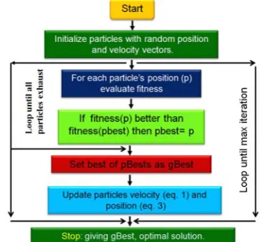
Particle Swarm Optimization is an evolutionary computation algorithm developed by Kennedy and Eberhart in 1995 [14]. PSO mimics the social behavior of a flock of birds where information is shared among the individuals of the population. It starts with an initial swarm of random particles in the search space where each particle is also assigned a randomized velocity. The velocity of each particle is dynamically updated based on the particle’s best previous position reached and the best position reached among previous generations [14].
The position and the velocity of a particle in a PSO algorithm is updated at each iteration towards its Pi and Pg positions according to (18) and (19):
) x p ().( rand . c
) x p ().( rand . c v . w v
id gd 2
id id 1
id id
− +
− +
=
(18)
id id
id x v
x = + (19)
where w is inertia weight, c1 and c2 are acceleration constants, and rand() is a random function in the range [0, 1]. The first term in (18) represents the inertia of previous velocity, the second is the “cognition” part which represents the private thinking of a particle, and the third term is the “social” part which represents the sharing of information among the population. The velocity of each particle is limited by Vmax when the updated velocity exceeds this value. Vmax is determined by the user and represents the resolution of the search process between the present position and the target position [14]. The flowchart of this algorithm is shown in Fig. 6. More details about this algorithm are presented in [14].
Fig. 6 Flowchart of the particle swarm optimization (PSO)
[14].
In this optimization problem the objective function is (17). Optimization variables are the height of magnet (hm), Magnet width (wM), central Magnet width (wcM), motor length (L) and air gap length (g) with constrains mentioned in table 2.
5 Results
The method described in section 4-2 is used to optimize the design of a typical air cored LPMS motor with specifications as presented in Table 1. Optimization is done in four cases, resulting different designs. These cases are explained in section 4-1.
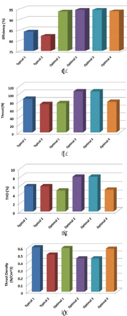
Design variables in these cases are listed in table 4. Table 5 and Fig. 7 show the characteristics of motor in the different optimization problems and those of two typical motors.
It can be seen in table 5 and Fig. 7 that the typical motor 1 with N40 as magnets has the efficiency of 84.2%, thrust and THD of 87.35 N and 5.82% respectively. The ratio of thrust to PM volume in this motor is 0.6 N/Cm3. In the typical motor 2 all the dimensions are equal to the first one and just the material of magnets are changed to a low quality one (N27). The characteristic of this motor are depicted as the efficiency of 82.18%, thrust, THD and thrust per PM volume of 73.7 N, 5.82% and 0.5 N/Cm3 respectively.
Although it was predictable that using the high quality magnet improves some characteristics, its cost is high and it can deteriorate some other characteristics such as thrust and thrust density.
Optimal design 1 is carried out considering THD of By as objective function. In this optimization THD is reduced almost 16.83% with respect to the typical motors. Table 5 shows that although efficiency is not considered in optimization process, it improved almost 11.34% with respect to the first motor. The average thrust is deteriorated about 12.71% with respect to the typical motor 1. Although the thrust density is collapsed about 1.6% with respect to the first motor, it improved about 18% with respect to the second motor.
In optimal design 2 we just optimized thrust. Results shows motor thrust has improved more than 22.24% and increased to 106.78 N. at the same time efficiency improved 12.28% too. But the thrust density and THD are deteriorated with respect to the both motors. The THD has increased to 8.03% in this case.
The results of optimal design 3 are similar to the optimal design 2. It means that maximum efficiency accompanies the maximum thrust (it is obvious from the comparisons of Figs. 5-a, b with Figs. 5-g, h).
Thrust, efficiency, and thrust ripple are simultaneously considered in the objective function by deciding nonzero values for m, n and k in (17).
Table 4 Dimensions of optimized motor for different objective functions.
Parameter Typical motor 1, 2
Optimal Design 1
Optimal Design 2
Optimal
Design 3 Optimal Design 4
m=1, n=k=0 n=1, m=k =0 m=n =0 k=1, m= 0.7, n=1.1, k=1
Air gap length [mm] 8.5 10.02 11 11 10.1
Magnet Width [mm] 37.8 32.12 41.97 41.97 33.03
Central Magnet
width [mm] 0 18.28 26.46 26.46 19.03
Magnet height [mm] 4.8 5.04 7 7 5.22
Motor Width [mm] 90 94.28 110 110 95.72
Table 5 The characteristics of optimized motor.
Parameter Typ.mot. 1 Typ.mot. 2 Opt. Design 1
Opt. Design 2
Opt. Design 3
Opt. Design 4
Efficiency (%) 84.2 82.18 93.75 94.54 94.54 93.86
Thrust (N) 87.35 73.7 76.26
106.78 106.78 79.47
THD (%) 5.82 5.82
4.84 8.03 8.03 5.03
Thrust/Vol.
(N/Cm3) 0.6 0.5 0.59 0.45 0.45 0.58
(a)
(b)
(c)
(d)
Fig. 7 The characteristics of the typical and optimized motors.
Although the values of coefficients in general depends on the designer’s will and the requirement of the motor application; here more emphasis is placed on the maximization of efficiency rather than the minimization of thrust ripple by choosing m=0.7, n=1.1 and k=1. In the last case the results of the design optimization show that motor thrust has improved 9.02% in the worst case and on the other hand this multi-objective optimization provides a design with almost 13.57% less thrust ripple (THD) and 11.47%
more efficiency with respect to the typical motor 1, while the thrust density is almost constant with respect to the first motor and is increased with respect to the second motor and high quality PM's consumption is decreased. This proves the effectiveness of the proposed optimization in simultaneously meeting all the objectives.
6 Design Evaluation
The design optimizations in this paper were carried out based on the analytical model of the machine presented in Section 2. This model is obtained by some simplifications such as ignoring saturation and considering a limited motor length. Thus, it is necessary to evaluate the extent of model accuracy. In this section, 2-D nonlinear time-stepping FEM is employed to validate the model. It is supposed that the motor is controlled by using a current-controlled inverter. The relative movement is taken into account in the FEM by using time-stepping analysis and Lagrange multiplier method [3].
A flowchart of the FEM is shown in Fig. 8. The 2-D FEM is carried out by a commercial package and numerical and graphical results are obtained. Fig. 9 shows a graphical representation of the flux lines and flux density distribution in the two typical motors and optimal design 4. Fig. 10 shows the flux density distribution in a pole pitch for the mentioned designs. It can be resulted from Fig. 10 that the flux density of optimal design 4 is more near to sinusoidal one and it leads to less THD for optimal design 4.
7 Conclusions
In this paper a novel multi-objective optimization method based on particle swarm optimization (PSO) is used to optimize the design of air core linear permanent magnet synchronous motor using modular poles. Central and lateral PM dimensions in addition to motor width and air gap are chosen as design variables and the objective functions are improving efficiency and motor thrust with low thrust force ripples. Since low magnet consumption and thrust density are major factors in the design and performance of LPMS motors, we have calculated and compared these items in each optimization steps.
We chose total harmonic distortion of normal magnetic flux density instead of the thrust ripples. Because it seems that by minimizing the total harmonic distortion of By, the force pulsations can be minimized. Optimization has carried out in four cases and in three of them only one objective function has been optimized and in the last one a multi-objective optimization has been carried out. The multi-objective optimization simultaneously provides a 9.02% more thrust in the worst case and almost 13.57% less thrust ripple (THD) and 11.47% more efficiency with respect to the typical motor 1, while the thrust density is almost constant in the worst case and high quality PM's consumption is
decreased. The validity of the performed design optimizations are confirmed by a 2-D finite element method.
Fig. 8 Flowchart of FEA [3].
(a) flux lines in typical motor 1
(b) flux lines in typical motor 2
(c) flux lines in optimal design 4
(d) flux density distribution in typical motor1
(e) flux density distribution in typical motor 2
(f) flux density distribution in optimal design 4
Fig. 9 Flux lines and flux density distribution in the LPMS
motors.
Fig. 10 Flux density distribution in a pole pitch for different
motors.
References
[1] Kim M. Y., Kim Y. C. and Kim G. T., "Design of Slotless-type PMLSM for High Power Density Using Divided PM," IEEE Trans. on Magnetics, Vol. 40, No. 2, pp. 746-749, March 2004.
[2] Isfahani A. H. and Vaez-Zadeh S., "Design optimization of a linear permanent magnet synchronous motor for extra low force pulsations," Elsevier, Energy Conversion and Management, Vol. 48, No. 2, pp. 443-449, 2007. [3] Vaez-Zadeh S. and Isfahani A. H.,
"Multiobjective Design Optimization of Air-Core Linear Permanent-Magnet Synchronous Motors for Improved Thrust and Low Magnet Consumption," IEEE Trans. On Magnetics, Vol. 42, No. 3, pp. 446-452, March 2006.
[4] Lim K. C., Woo J. K., Kang G. H., Hong J. P. and Kim G. T., "Detent Force Minimization Techniques in Permanent Magnet Linear Synchronous Motors," IEEE Tran. on Magnetics, Vol. 38, No. 2, pp. 1157-1160, March 2002. [5] Akmese R. and Eastham J. F., “Design of
permanent magnet flat linear motors for standstill application,” IEEE Trans. Magn., Vol. 28, No. 5, pp. 3042-3044, Sep. 1992.
[6] Moghani J. S., Eastham J. F., Akmese R. and Hill-Conttingham R. J., “Three dimensional force prediction in a model linear brushless DC motor,” IEEE Trans. Magn., Vol. 30, No. 6, pp. 4752-4754, Nov. 1994.
[7] Chen S. X., Low T. S., Mah Y. A. and Jabber M. A., “Super convergence theory and its application to precision force calculation,” IEEE Trans. Magn., Vol. 32, pp. 4275-4277, Sep. 1996.
[8] Felores Filho A. F., Nakata T. and Takahashi N., “Three dimensional computation of force in a novel brushless DC linear motor,” IEEE Trans. Magn., Vol. 33, No. 2, pp. 2030-2032, Mar. 1997. [9] Cvetkovsk G., Petkovska L. and Gair S.,
"Efficiency Improvement of PM Disc Motor Using Genetic Algorithm", proceedings of 9th Spanish Portuguese Congress on Electrical Engineering, 9CHLIE’2005 on CD, Marbella, Spain, pp. 1-7, 2005.
[10] Otten G., de Vries T.J.A., van Amerongen J., Rankers A.M. and Gaal E.W., “Linear Motor Motion Control Using a Learning Feedforward Controller,” IEEE IASME Transactions on Mechatronics, Vol. 2, No. 3, pp. 179-187,1997. [11] Rohrig C. and Jochheim A., " Identification and
Compensation of Force Ripple in Linear Permanent Magnet Motors," Proceedings of the American Control Conference Arlington, pp. 2161-2166, June 25-27, 2001.
[12] Chung M. J., Lee M. G., Lee S. Q. and Gweon D., " Optimal Design and Development of Linear Brushless Permanent Magnet Motor," IEEE conference, pp. 436-441, 2001.
[13] Isfahani A. H., Vaez-zadeh S. and Rahman M. A., "Using Modular Pole for Shape Optimization of Flux Density Distribution in Permanent-Magnet Machines," IEEE Trans. On Magnetics, Vol. 44, No. 8, pp. 1009-2015, August 2008.
[14] Arkadan A. A., ElBsat M. N. and Mneimneh M. A., "Particle Swarm Design Optimization of ALA Rotor SynRM for Traction Applications," IEEE Trans. On Magnetics, Vol. 45, No. 3, pp. 956-959, March 2009.
Caro Lucas received the M.S. degree
from the University of Tehran, Tehran, Iran in 1973 and the Ph.D. degree from the University of California, Berkeley, in 1976. He is a Professor, and a member (as well as the founder-Director) of Center of Excellence for Control and Intelligent Processing, Department of Electrical and Computer Engineering, University of Tehran, as well as a Researcher at the School of Cognitive Sciences (SCS), Institute for Studies in Theoretical Physics and Mathematics (IPM), Tehran, Iran. He has served as the Director of Intelligent Systems Research Faculty, IPM (1993-1997) and Chairman of the ECE Department at the University of Tehran (1986-1988). He was also a Visiting Associate Professor at the University of Toronto, Toronto, Canada (summer, 1989-1990), University of California, Berkeley (1988-1989), an Assistant Professor at Garyounis University (1984-1985), University of California, Los Angeles (1975-1976), a Senior Researcher at the International Center for Theoretical Physics, and the International Center for Genetic Engineering and Biotechnology, both in Trieste, Italy, the Institute of Applied Mathematics, Chinese Academy of Sciences, Harbin Institute of Electrical Technology, a Research Associate at the Manufacturing Research Corporation of Ontario, and a Research Assistant at the Electronic Research Laboratory, University of California, Berkeley. His research interests include biological computing, computational intelligence, uncertain systems, intelligent control, neural networks, multiagent systems, data mining, business intelligence, financial modeling, and knowledge management. He was the founder of the ISRF, IPM and has assisted in founding several new research organizations and engineering disciplines in Iran. He is the holder of the patent for Speaker Independent Farsi Isolated Word Neurorecognizer. Dr. Lucas has served as Managing Editor of the Memories of the Engineering Faculty, University of Tehran (1979-1991), Reviewer of Mathematical Reviewers (since 1987), Associate Editor of the Journal of Intelligent and Fuzzy Systems (1992-1999), and Chairman of the IEEE, Iran Section (1990-1992). He has served as the Chairman of several international conferences.
Zahra Nasiri-Gheidari has received her
B.Sc. degrees in Electrical Engineering from the Iran University of Sciences and Technology, Tehran, Iran in 2004. And she received the Master degrees in Electrical Power Engineering from the University of Tehran in Iran in 2006, graduating with First Class Honors in
both of them. She is now working toward the PhD. degree at the University of Tehran, Tehran, Iran. Her research interests include design and modeling of electrical machines and finite-element analysis of electromagnetic devices.
Farid Tootoonchian has received his
B.Sc. and M.Sc. degrees in Electrical Engineering from the Iran University of Sciences and Technology, Tehran, Iran in 2000 & 2007 respectively. He has done over 21 industrial projects including one national project about electrical machines over the years, and holds 5 patents. He is now PhD. Candidate at K. N. Toosi University of Technology, Tehran, Iran. His research interest is design and finite-element analysis of small electromagnetic sensors and machines.
![Fig. 4 A layer model of an air core LPMS motor [2].](https://thumb-us.123doks.com/thumbv2/123dok_us/215908.2016042/3.595.61.226.345.547/fig-layer-model-air-core-lpms-motor.webp)
![Table 1 The parameters of original motor [3].](https://thumb-us.123doks.com/thumbv2/123dok_us/215908.2016042/4.595.309.541.473.754/table-parameters-original-motor.webp)
![Fig. 8 Flowchart of FEA [3].](https://thumb-us.123doks.com/thumbv2/123dok_us/215908.2016042/8.595.316.559.83.510/fig-flowchart-of-fea.webp)
