TMS320F2812 BASED
IMPLEMENTATION OF SENSORLESS
CONTROL FOR BLDC MOTOR
Mr.R.VIJAYARAJESWARAN
Managing Director, vi micro systems pvt.Ltd.
Chennai. Tamilnadu, India,
Email id :[email protected]
Abstract: The paper attempts to develop a novel sensorless control scheme suitable for brushless dc permanent magnet (BLDC-PM) motor with a view to elaborate its flexible operating status. It orients its focus to detect the zero crossing instant of the back emf and there from assuage a methodology to control the speed of the motor. The state of the art technology facilitates the use of a powerful processor to realize the strategy in real time. It includes MATLAB simulation to evaluate its performance and seeks the role of DSP (Digital Signal Processor) TMS320F2812 controller to validate the same using a prototype. The results illustrate the ability of the proposed technique to improve the input power factor in addition to regulating the speed of the motor.
Keywords:Sensorless control; DSP; Back EMF; Speed Regulation.
I Introduction
The drive industry continues to experience a reformation in view of the elaborate automation and exhaustive sophistication. Though a large number of electric motors are available still the Brushless Direct Current (BLDC) motors appear to gain popularity on account of better speed versus torque characteristics, improved dynamic response, higher efficiency, longer operating life, noiseless operation and higher speed ranges. They are widely used in appliance, automotive, aerospace, consumer and medical industries.
The BLDC motors are electronically commutated and are usually operated with one or more position sensors. It is desirable to run the motor without position sensors and therefore prefer a sensorless operation.
A Fuzzy logic controller has been designed for a BLDC permanent magnet motor drive. The simulation and TMS320F2808 DSP based experimental results have been found to portray the superior performance of its dynamic characteristics [10]. An efficient simulation model for fuzzy logic controlled brushless direct current motor drives using Matlab/Simulink has been presented. The dynamic characteristics of the BLDC motor (i.e. speed and torque) and as well as currents and voltages of the inverter components have been analyzed using the developed model [11].
A current control mechanism for BLDC motors based on a mean DC signal (i.e., generation of quasi-square wave currents using only one current controller for three phases) has been suggested. It has been to successfully remove
excessive current and consequent back EMF present at the end of the commutation period and result in improvement in efficiency and lower acoustic noise [12].
A speed regulation scheme for a small BLDC motor with trapezoidal back-emf has been proposed. The control Strategy has been found to use the proportional controller where the proportional gain, kp, has been appropriately adjusted using a genetic algorithm. The scheme has been found to perform well in order to compensate the BLDC motor with load disturbance [13].
II Proposed Statement
simulation and implementation using a Digital Signal Processor (DSP) based experimental arrangement to bring out its applicability.
III Proposed Approach
Commutation in sensorless control strategy is based on indirect rotor position information. It revolves around the phenomenon of identifying the zero crossing instant of the BEMF that ideally acquires a unique position within an electrical cycle. The position dynamically varies and is monitored through an appropriate mechanism.
The sensorless control based on zero-crossing detection of BEMF claims the advantages of its suitability of use on a wide range of both Y and Δ connected 3-phase motors. It is relatively insensitive to motor manufacturing tolerance variations and found to work satisfactorily for either voltage or current control.
The Power module seen in Fig. 1 is constituted of a three phase MOSFET based PWM Inverter and involves the use of V/F algorithm to accelerate the motor regardless of its actual position. It starts with an initial hazzle because of the unknown rotor position and there after the motor proceeds using the reference voltage and frequency irrespective of the position of the rotor.
When the BLDC motor rotates, each winding generates BEMF that can be calculated using equation (1). BEMF = Nlrbω - (1)
Where
N= number of winding turns per phase l = length of the rotor
r = internal radius of the rotor B = rotor magnetic field density ω = motor angular velocity
Fig.1 Power Module
It is apparent from the expression that BEMF is governed only through the angular velocity or speed of the rotor. The Sensor less control of BLDC motor calls for commutation based on the BEMF produced in the stator windings. The theory shows that only two out of three phases are excited at any instant of time. The PWM drive signal can be applied either in the high or low or on both sides.
The operating equations are written as
b a
i
i
=
−
,i
cAGND A A AGND nGND
e
dt
di
L
R
i
v
v
=
−
(
+
)
−
(1)BGND A A BGND nGND
e
dt
di
L
R
i
v
v
=
+
(
+
)
−
(2)
GND GND
GND n c
C
v
e
v
=
+
=GND GND GND GND GND C B A B A
e
e
e
v
v
+
+
−
+
2
2
(3)Where
v
nGND is the neutral point voltage.But
e
AGND+
e
BGND=
0
So
GND GND
GND
GND C
B A
C e
v v
v = + +
2 (5)
The above equations reflect the situation in Fig.1 where C is the non-energized phase. The BEMF appears to
pass through zero, through a comparison of GND C
v
with half Vdc and serves to devise a strategy that realizesthe voltage sampling after PWM ON time. If
GND C
e
is equal to zero, the terminal voltage on phase C is equal to half of the sum (Vdc+0, with respect to the ground). It thus becomes necessary to monitor all the three phase terminal voltages and the DC supply voltage using potential dividers and ADCs to identify during appropriate sectors, when the phase BEMFs cross zero. However only one phase voltage is required to be monitored for a given sector.There is a need to synchronize the rotating magnetic field in the stator with the MMF vector in the rotor, above a certain speed, when BEMF zero-crossing detection is feasible. A ZCD window is created taking into consideration the commutation period. The ZCD signal is allowed to occur “in the middle” of the commutation period and ensure that each phase is powered through the ZCD pattern. However it turns out that “secure” zero-crossing detection is assured only for minimum 20% duty-cycle.
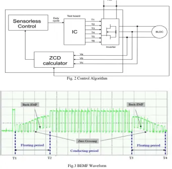
IV Control Algorithm
The ZCD in the control circuit seen in Fig. 2 is a toggle signal that changes from 1 to 0 each time the BEMF from one phase passes through zero. The zero crossing of back emf is shown in the Fig.3.
Fig. 2 Control Algorithm
Fig.3 BEMF Waveform
The ZCD circuit detects the crossings of back emf signal and attempts to generate the PWM signals for the power switches in the inverter to the drive BLDC motor in the sensor less mode.
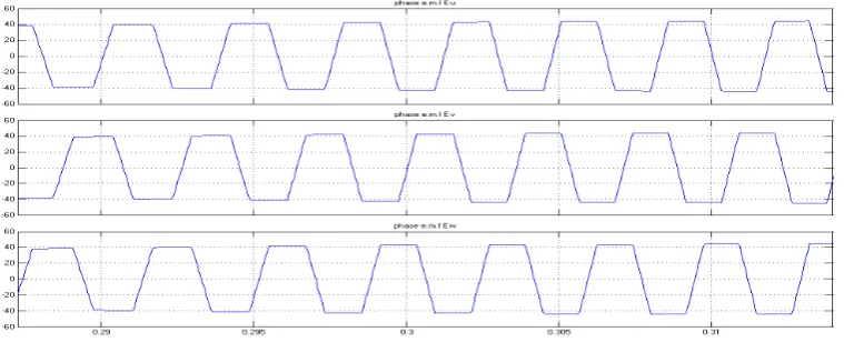
V Simulation
the speed regulating characteristics of the Sensorless approach in the event of the motor being subjected to step changes in load and reference speed respectively.
Fig. 4 Back emf in V/F control
Fig. 5 PWM pulse in V/F control
The BEMF and ZCD signals obtained in the sensorless mode, with a PI corrective action to control the speed are drawn in Figs.6 and 7
Fig. 7 PWM pulse in sensorless control
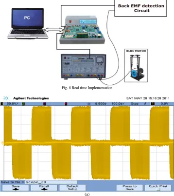
VI Real time implementation
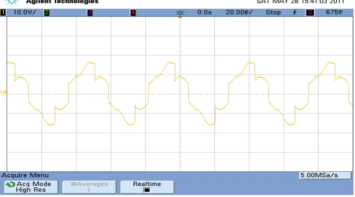
The scheme implemented in real time using a 1.1 HP, 4600 rpm, 310 volts BLDC-PM motor is shown in Fig. 8. The back emf waveforms without filtering , with filtering and PWM pulses for both V/F control and sensorless control are shown in the Figs 9 ,10 ,11 and 12 respectively.
Fig. 8 Real time Implementation
(b)
Fig. 9.Back emf (a) Without filtering (b) With filtering in V/F control
Fig. 10 Back emf and PWM pulse in V/F control
(b)
Fig. 11.Back emf without filtering and with filtering in sensorless control
Fig. 12 PWM pulse in sensorless control
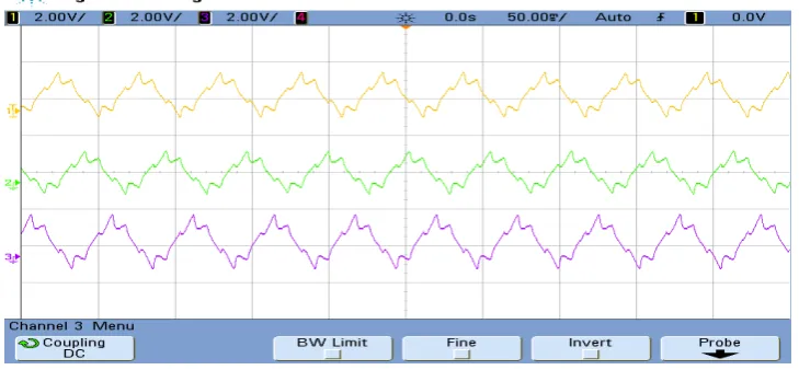
The three phase current wave forms for V/F control and sensor less control are shown in the Figs.13 and 14. It is observed that the current wave forms in V/F control are notsymmetrical because of switching that takes place without knowing the actual position of the rotor.
Fig. 14Current waveforms in sensorless control
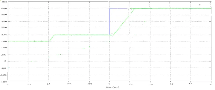
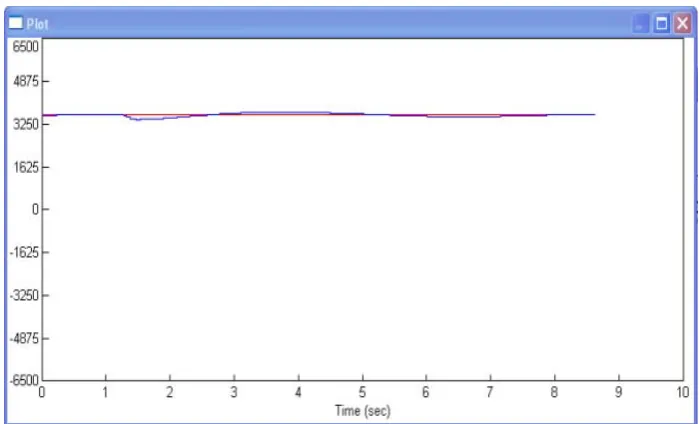
Fig. 15 Speed Vs Time waveform with a step change in load
Fig. 17 Speed Vs Time waveform with a step change in load
Fig.18 Speed Vs Time waveform a step change in reference speed
The speed regulating characteristics of the Sensorless approach in the event of the motor being subjected to step changes in load and reference speed respectively. The servo and regulatory responses obtained through simulation is seen in Figs.15 and 16. The same adequately valuated through experimental results in Figs 17 and 18 exhibit the ability of the scheme to allow the motor to reject the disturbances and reach steady state in reasonably quick time.
VII performance Comparison
TABLE 1 . COMPARISON OF INPUT POWER FACTOR AND SPEED REGULATION
VIII Conclusion
A novel sensorless control strategy has been developed to regulate the speed and improve the input power factor of an inverter fed BLDC-PM motor. It has been based on seamless commutation to BEMF zero-crossing detection. The TMS320F2812 controller has been found to offer an easy way of real-time implementation that does not require large computation time. The performance has been found to enhance the input power factor and thereby minimize the system VAR requirements, in addition to yielding a regulated speed over the entire operating range. It can be inferred that the proposed methodology will go a long way in exploring innovative applications in this domain.
IX References
[1] A.Ungurean, V. Coroban-Schramel and I. Boldea, IEEE Fellow “Sensorless control of a BLDC PM motor based on I-f starting and Back-EMF zero-crossing detection” 12th International Conference on Optimization of Electrical and Electronic Equipment, OPTIM 2010
[2] Yen-Shin Lai, Yong-Kai Lin, "Back-EMF Detection Technique of Brushless DC Motor Drives for Wide Range Control”, IEEE Trans. On Power Electronics, No. 6, pp 1006-1011, 2006
[3] Y. S. Lai, F. S. Shyu, and Y. H. Chang, "Novel loss reduction pulse width modulation technique for brushless DC motor drives fed by MOSFET inverter," IEEE Trans. on Power Electronics, Vol. 19, No. 6, pp. 1646-1652, 2004.
[4] K. Iizaka, H. Uzuhashi,M. Kano, T. Endo, and K. Mohri, “Microcomputer control for sensorless brushless DC motor,” IEEETrans. Ind. Applicat., vol. IA-21,p p. 595-601,M ay/June 1985.
[5] S.Ogasawara and H. Akagi,“Anapproach toposition sensorless drive for brushless DC motor,” IEEE Trans. Ind. Applicat., vol. IA 27, pp. 928-933,O ct. 1991
[6] R.Mizutani, T. Takeshita, and N.Matsui, “Cmnt model-based sensorless drives of salient-pole PMSM at low speed and standstill,”
IEEE Trans. Ind. Applicat., vol. 34,pp. 841-846, July/Aug., 1998.
[7] J.P.Johnson, M.Ehsani, and Y.Guzelgunler, “Review of sensorless methods for brushless DC,” IEEE IAS Annual Meeting Con$ Rec.vol. pp. 1033-1040, 1999.
[8] Wook-Jin Lee, Seung-Ki Sul, ”A New Starting Method of BLDC Motors Without Position Sensors”, IEEE Transactions on Industry Applications, Vol. 42, No. 6, pp 1532-1538, 2006
[9] Zhiwei Zhang; Libing Zhou,” Position sensorless control for permanent-magnet brushless DC motor based on ASIC ML4425”, Power Electronics and Motion Control Conference, 2009. IPEMC '09.IEEE 6th International, pp 1903 – 1905, 17-20 May 2009.
[10] Tan Chee Siong, Baharuddin Ismail, Siti Fatimah Siraj, Mohd Fayzul Mohammed, “Fuzzy Logic Controller for BLDC Permanent Magnet Motor Drives”, International Journal of Electrical & Computer Sciences IJECS-IJENS Vol. 11 No. 02, pp 13-18, April 2011. [11] Mehmet Cunkas, Omer Aydoğdu, “Realization of fuzzy logic controlled brushless dc motor drives using Matlab/simulink”,
Mathematical and Computational Applications, Vol. 15, No. 2, pp. 218-229, 2010.
[12] G.MadhusudhanaRao, Dr. B.V.SankerRam, “Speed Control of BLDC Motor with Common Current”, International Journal of Recent Trends in Engineering, Vol 2, No. 6, pp 182-187, November 2009.
[13] S. Poonsawat, T. Kulworawanichpong, “Speed Regulation of a Small BLDC Motor using Genetic-Based Proportional Control”, World Academy of Science, Engineering and Technology, 47, pp 232-237, 2008
Open loop control Closed loop control (Reference speed=4000 RPM) Current
in amps
Power factor in Hall sensor mode
Power factor in sensor less mode
Speed in Hall sensor mode
(RPM)
Speed in sensor less mode
(RPM)
Speed in Hall sensor mode
(RPM)
Speed in sensor less mode (RPM) Simulation Real Time Simulation Real Time Simulation Real Time Simulation Real Time Simulation Real Time Simulation Real Time 0.8 0.65 0.65 0.73 0.71 3381 3364 3385 3369 3999 3981 4000 3985
1.5 0.67 0.67 0.75 0.74 3175 3160 3179 3165 3991 3985 3996 3988
2.2 0.68 0.71 0.78 0.76 3021 3006 3024 3008 3990 3986 3992 3986
3 0.74 0.73 0.81 0.78 2901 2890 2905 2893 3992 3984 3994 3989