GSJ: Volume 7, Issue 9, September 2019, Online: ISSN 2320-9186
www.globalscientificjournal.comMODELING
OF
ECCENTRICITY
AND
PERFORMANCE
OF
INDUCTION
MOTORS
OLALEYE, Samuel Olalowo
HND (Bida) PGD (RSU) M.Tech(RSU)
(PG.2016/03739)
A THESIS SUBMITTED TO THE DEPARTMENT OF POST GRADUATE SCHOOL, RIVERS STATE UNIVERSITY, NKPOLU-OROWORUKWO, PORT HARCOURT IN PARTIAL FULFILMENT OF THE REQUIREMENTS FOR THE AWARD OF DOCTOR OF PHILOSOPHY (PHD) DEGREE IN ELECTRICAL ENGINEERING OF THE DEPARTMENT OF ELECTRICAL ENGINEERING.
Supervisors
Prof. D.C. Idoniboyeobu Prof. C. O. Ahiakwo Dr. S. Orike
TABLE OF CONTENTS
Title Page i
Table of Contents ii
CHAPTER 1 – INTRODUCTION 1.1 Background of Study 1
1.2 Problem Statement 6
1.3 Aim of Study 7
1.4 Objectives of Study 7
1.5 Significance of Study 7
1.6 Scope of Study 7
1.7 Limitation of Work 7
1.8 Organization of Study 8
CHAPTER 2 – LITERATURE REVIEW 2.1 Overview of Faults in Asynchronous Motors 9
2.1.1 Overloading 10
2.1.2 Single Phasing 11
2.1.3 Unbalanced Supply Voltage 12
2.1.4 Locked Rotor 12
2.1.5 Phase Reversal 13
2.1.7 Under Voltage 14
2.1.8 Over Voltage 14
2.1.9 Open Circuit 14
2.1.10 Motor Out-Of-Magnetic Center 15
2.1.11 Broken Rotor Bars 15
2.1.12 Stator Winding Faults 15
2.1.12 Turn-to-Turn Shorts in The Stator Windings 17
2.2 Airgap Eccentricity Fault 19
2.3 Eccentricity Detection Techniques 21
2.3.1 Normalized Splitting Severity (NSS) Factor 21
2.3.2 Difference of Area Under Park‘s Vector Current for Two Consecutive Current Cycles To The Average Of All The Areas (APC) 23
2.3.3 High-Frequency Component of Stator (HFS) Current 23
2.3.4 Low-Frequency Component of Stator (LFS) Current 24
2.3.5 Stator Current‘s Low and High (SLH) Frequency Component 25
2.3.6 Ratio of Summation of Low-Frequency Stator Current Components and No-Load Current of Motor (RSN) 25
2.3.7 Gyration Radius of The Torque Developed (GRT) 26
CHAPTER 2 – The Modeling of Asynchronous Motors
3.1 Design Technique of Induction Motor 28
3.2 Power Analysis for Induction Motor 31
3.3 Modeling Framework of Induction Motor 35
3.4 Stored Energy Derivable Inductance Equations 38
3.5 Airgap Eccentricity Modeling 41
REFERENCES 93
CHAPTER 1
INTRODUCTION
1.1 Background of Study
In industrial applications, 35% - 40% of the generated electrical energy is consumed by electrical
motors, (Nandi et al, 2005). Electrical machines are equipment using electromagnetic forces.
generators, (Aderiano, 2006). An electrical motor can either be a synchronous motor or
asynchronous (induction) motors.
The first electric induction motor was fabricated over 100 years ago by Arno, (Arno, 1863).
Bollee, (Bollee, 1969) believed that this motor exploited a dielectric hysteresis effect in the glass
and ebony rotors that Arno used. Since that time, very little research has been conducted, as
several authors have noted, (Bart, 1990), (Bart & Lang, 1989), (Krein & Crowley, 1985). The
modern form of the electric induction machine, which employs free surface charge, was first
fabricated 30 years ago, and measurements of the starting torque were made as a function of
excitation frequency (Choi & Dunn, 1971). Building upon these results, other authors fabricated
similar electric induction motors, (Mognaschi & Calderwood, 1990), (Mognaschi & Calderwood,
1991), and some investigated non-ideal effects inherent to the electric machine, (Krein &
Crowley, 1985), ((Mognaschi & Calderwood, 1995). The governing equations were explored on
by Kooy, (Kooy , 1969) and Ubbink, (Ubbink 1970) and more recently by (Bart & Lang, 1989),
(Mognaschi & Calderwood, 1990).
Asynchronous motors are used all over the world as the workhorse in industrial applications.
Within the industrial electrical motor applications, more than 90% of the motors are three-phase
induction motors, (Bonnett & Soukup, 1992) They are robust machines used for general
purposes like industrial pumps, conveyors, machine tools, centrifugal machines, presses,
elevators, packaging equipment and indeed all motor horse-powers. In hazardous locations, their
applications include petrochemical and natural gas plants, (Langsdorf, 1974). They are also used
in severe setups as grain elevators, shredders and equipment for coal plants.
The popularity of induction machines is due to their robustness, high efficiency, and low cost,
and have high efficiency, (Ferreira & Almeida, 2006). Additionally, the wide range of
asynchronous motors power of which is from hundreds of watts to megawatts satisfies the
production needs of most industrial processes, (Almeida et al, 2014).
Despite these many outstanding features of induction motors, they are still prone to many types
of faults in industrial applications (Thorsen & Dalva,1999). Some of these faults and failure
conditions are rotor broken bar, mass unbalance, stator faults, single phasing, crawling, bearing
faults etc. Research shows that the most vulnerable parts for fault in the induction motor are
bearing, stator winding, rotor bar, and shaft, (Radu, 2010).
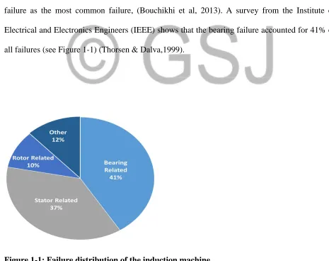
An overview of all the various types of failures in asynchronous motors concisely puts bearing
failure as the most common failure, (Bouchikhi et al, 2013). A survey from the Institute of
Electrical and Electronics Engineers (IEEE) shows that the bearing failure accounted for 41% of
all failures (see Figure 1-1) (Thorsen & Dalva,1999).
Source: Thorsen & Dalva,1999
In the petrochemical industry, the bearing faults constitute 52% of the induction machine faults,
(Vencl et al, 2007). Induction machines are the dominant type of technology used in medium and
large wind turbines, (Cao et al, 2012). For the induction machines used in military purposes,
which are installed in warships, the bearing failures can go as high as 95% of the total failures
because of high shock loading and harsh environments, (Tavner & Hasson, 1999).The causes of
bearing failure can be distributed into: inappropriate lubrication of the bearing rolling element
(80%), inadequate bearing selection (10%), improper mounting (5%), indirect failure (4%), and
manufacturing error (1%), (Radu, 2010).Certainly, the indirect failure is caused by overloading,
vibration, electric discharge, and temperature, (Modh et al, 2016).
Faults in induction motors can be categorized as follows:
(a) Electrical-related faults: Faults under this classification are unbalance supply voltage or
current, single phasing, under or over voltage of current, reverse phase sequence, earth
fault, overload, inter-turn short-circuit fault, and crawling. The stator related fault is the
biggest contributor under this category (Bakhri, 2013). This being so because if a small
fault in a stator is not detected timely, complete motor failure can occur more quickly
than with other faults.
(b) Mechanical-related faults: Faults under this classification are broken rotor bar, mass
unbalance, air gap eccentricity, bearing damage, rotor winding failure, and stator winding
failure.(Singh & Kazzaz, 2003).
(c) Environmental-related faults: Ambient temperature as well as external moisture will
due to any reason such as installation defect, foundation defect, etc., will also affect the
performance.
Table 1.1 Fault occurrence possibility on induction motor
Source: Allbrecht et al, 1986
A motor failure that is not identified in an initial stage may become catastrophic and the
induction motor may suffer severe damage. Thus, undetected motor faults may cascade into
motor failure, which in turn may cause production shutdowns. Such shutdowns are costly in
terms of lost production time, maintenance costs, and wasted raw materials (Vencl et al, 2007).
Additionally, induction motors are more susceptible to faults when supplied by alternating circuit
(ac) drives,(Raison et al, 2002). This is due to the extra voltage stress on the stator windings, the
high frequency stator current components, and the induced bearing currents, caused by ac drives.
In addition, motor over voltages can occur because of the length of cable connections between a
motor and an alternating current drive. This last effect is caused by reflected wave transient
voltages. Such electrical stresses (Obaid et al, 2003), may produce stator winding short circuits
and result in a complete motor failure.
Besides, due to non-uniformity of the airgap between stator-inner surface and rotor-outer surface
motor, eccentricity faults also occur. Many researches on electrical machines summarily show,
Any eccentricity in the machine will create excessive mechanical stress and cause more fatigue
in the bearings, (Stephan, 2005).
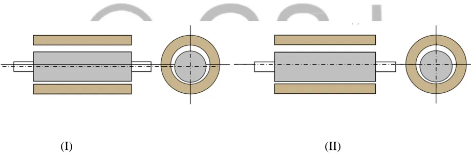
Basically, there are 2 types of eccentricities in induction motors, viz:
(I) Static Eccentricity: A rotor eccentricity is said to be static when the rotor rotates on
its own axis but not at the centre of the stator bore which causes the 2-times supply
frequency force to act towards the direction of the narrowest airgap (Dorrell, 1993).
See this shown in Figure 1.2 (I).
(II) Dynamic Eccentricity: This type of eccentricity occurs when the rotor rotates at the
centre of the stator bore axis but not on its own axis, in which case the minimum
airgap rotates with the rotor rotating frequency. This is depicted in Figure 1.2 (II).
(I) (II)
Figure 1.2: The 2 basic types of eccentricity: (I) static (II) dynamic
Source: Chuan & Shek, 2016
The degree of eccentricity,
ɛ
, is the ratio between the mean airgap length,g
0 and the length ofthe eccentricity rotor misalignment, . The degree of eccentricity can be written as:
The degree of eccentricity,
ɛ
from Figure 1.1 and the angle of the narrowest airgap isa function of both the static and dynamic eccentricity (Chuan & Shek, 2018), which is shown in
Figure 1-2.
B
=
(1.2)
Where,
Bis the magnetic flux density
p is the pole pair number J is the current density,
lm is the magnetic path length,
and,
u
e is the effective permeability1.2 Problem Statement
Asynchronous machines are the most widely used type of electrical machines because of their
robustness, simplicity, and relatively low cost. However, the small airgap in the induction
machine caused by eccentricity is unavoidable due to the manufacturing tolerance and 80% of
the mechanical faults could cause rotor eccentricity in electrical machines.
1.3 Aim of Study
The integral objective of this thesis is to model a control system to reduce eccentricity in
1.4 Objectives of Study
The specific objectives of this thesis are to:
1. Investigate the cause of static and dynamic eccentricity.
2. Analytically model concepts for the reduction of both types of eccentricities.
3. Simulate a cost-effective technique of reducing both types of eccentricities.
4. Improve the performance of three phase induction motors.
1.5 Significance of Study
This thesis hopes to achieve a performance improvement technique for induction motors as the
eccentricity faults are mitigated.
1.6 Scope of Work
1. This thesis work scope is strictly for 3-phase induction motors.
2. It is not applicable to synchronous motors.
1.7 Organization of Study
This thesis work is organized as follows. Chapter 2 presents a review of existing literatures on
asynchronous motors fault condition diagnosis and detection. In chapter 3, the material and
based on the obtained results from simulations whilst and discussion of the simulation results. In
Chapter 5, I conclude and make recommendation on my research.
CHAPTER 2
LITERATURE REVIEW
2.1 Overview of Faults in Asynchronous Motors
Induction motors being the power horses in industries have some faulty conditions that if not
fixed or resolved quickly can cause a complete downtime, (Mirafzal & Demerdash, 2016). Many
of the faults in induction motors result from manufacture defects, poor installation, mechanical
stress, electrical stress and environmental hazards, (Thorsen & Dalva, 1999). These affect
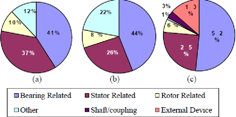
total asynchronous motor failures are bearing-related faults, followed by stator-related faults
which is about 37%, (Singh & Kazzaz, 2003) see Figure 2.1.
Figure 2.1 Distribution of common faults of induction motors
Sources:
EPRI survey results
(a) IEEE-IAS survey results &
(b)survey result in a petrochemical industry
Source: Bakhri, 2013
Some of these faults are enumerated below:
1. Over loading
2. Single phasing
4. Locked rotor
5. Phase reversal
6. Ground fault
7. Under voltage
8. Over voltage
9. Open circuit
10. Motor out-of-magnetic center
11. Broken rotor bars
12. Stator windings fault
2.1.1 Overloading
Overloading is a fault condition in an asynchronous motor experienced when the applied
mechanical load on the motor is greater than the specified full load rating specified by the
manufacturer. Basically here, the mechanical torque exceeds the threshold point. This fault
condition causes increased phase currents and over-heating, (Bonnett & Soukup, 1988). In a
traditional relay protection system, the overcurrent relay trips the motor off-line when the current
transformers (CT) encounter over current in the line.
2.1.2 Single Phasing
This is an unbalanced condition of induction motors whereby one of the three electrical power
winding and results into negative sequence current, (Masrur et al, 2009). A high-set
instantaneous trip unit relay and negative sequence relay are used in a legacy protection system
to diagnose this fault. (Elmore, 2004).
Effects of single phasing fault are as follows:
• For single phasing fault motor windings get over heated, primarily due to flow of negative
sequence current.
• If during running condition of the motor single phasing fault occurs motor continues to run due
to the torque produced by the remaining two phases and this torque is produced as per the
demand by the load—as a result healthy phases may be over loaded and hence over heated
resulting in critical damage to the motor itself.
• A three-phase motor will not start if a single phasing fault already exists in the supply line.
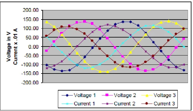
2.1.3 Unbalanced Supply Voltage
There are many causes of unbalance supply voltages such as unbalance loading, open delta
transformers and unequal tap setting. This condition leads to reduction in motor efficiency, raises
the motor temperature and excessive unbalanced full load current, (Sudha & Anbalagan, 2009).
Three-phase voltages and currents during an unbalanced supply are shown in Figure 2.1. A
Figure 2.2. Three-phase Voltages and Currents for Induction Motor Under Unbalanced
Supply Voltage.
Source: Hammo, 2014
2.1.4 Locked Rotor
Locked rotor fault occurs when electrical voltage is applied to a stationary induction motor.
Under this condition, the stator current may over shoot to about six times its rated value, (Sudha
& Anbalagan, 2009). There are many causes for this fault to occur, for instance; if the rotor shaft
is connected to heavy load the motor may experience locked rotor conditions. Locked rotor
causes high current which leads to heating the rotor. Therefore, locked rotor condition cannot be
withstood for a long time. The allowed duration of the motor overloaded under locked rotor
condition depends on the voltage applied to the motor terminals. Therefore, the protection
system should be able to disconnect the motor when locked rotor condition exceeds the amount
of allowed time. Traditional protective systems use over current relays with I-T characteristics,
2.1.5 Phase Reversal
Phase reversal occurs when any of the two phases are reversed from the normal sequence, which
leads the motor to rotate in the opposite direction. When the motor starts to rotate in the opposite
direction, it can cause intensive damage. Therefore, this condition should be corrected
immediately. Reverse-phase relays and negative sequence relays are used for the protection LR7
(Hammo, 2014).
2.1.6 Ground Fault
This is a fault condition experienced when any of the electrical power phases touches the ground.
When this happens, the motor runs under steady-state set speed conditions. During this time, the
induction motor can still run with reduced load subject to the application requirement since the
torque pulsations are high though. The impact of this fault is very huge as it causes hazards to
human safety and interfere with telecommunication systems, (Hammo, 2014). This fault is
diagnosable by measuring the ground leakage current, (Elmore, 2004).
2.1.7 Under Voltage
Under voltage fault is reducing the supply voltage on the three phases by specific percentage,
which impedes the motor from attaining rated speed in specified time, increases the current and
overheats the machine. Low voltage protection relays are used in traditional systems. However,
need a delay mechanism which delays the under-voltage protection for a period. This additional
mechanism needs high sensitive devices and involves calibrations (Elmore, 2004).
2.1.8 Over Voltage
Over voltage occurs if the three phase voltages are greater than rated voltage. The effect of this
fault is increasing current flow which leads to unacceptable stress on the motor insulation due to
high heat dissipation. Conventional protection systems use the over voltage relays to protect the
motor during this condition (Elmore, 2004).
2.1.9 Open Circuit
This open-circuit fault occurs when any of the phases becomes open-circuited. The torque pulses
in here are comparatively less as compared to that obtained during ground fault where one phase
is short-circuited to the ground. The fault mode current here is also very close and almost equal
the starting current. It is also possible for 2 phases to be open-circuited and even the three
complete phases. In a situation of two phases open circuited, both current and torque slowly
damp to zero. This leads to an outright stop of operation.
Finally, in a condition of all the three phases getting open-circuited, both current and torque
suddenly reach zero. This condition however takes a little extra time compared to the case of two
phases open-circuited. Thus, the motor grounds to a halt, (Faiz, 2017)
This condition normally occurs when the rotor is not positioned in the magnetic center of the
stator in the axial or lateral direction. An out-of-magnetic center condition could occur in the
radial direction when there is an uneven airgap between the rotor and stator. This problem may
not generate excessive vibration levels and is often overlooked because the data is not processed
with enough resolution to identify the problem.
2.1.11 Broken Rotor Bars
This problem is like the out-of-magnetic center problem. However, there are distinctive
differences. The similarity is that rotor speed is modulated by slip frequency times the number of
poles. A broken rotor bar, sometimes called open iron, creates a dead spot in the rotor and causes
sideband components, (Nandi et al, 2005), (Bellini et al, 2001), (Benbouzid, 2000). The resulting
electrical imbalance can generate significant vibration levels at one and two times RPM. Since
this problem is not interactive with line frequency, a spectral line at 60 Hz may not be present.
Once again, the data must be processed with enough resolution for accurate diagnosis. As a
result of this fault condition, there is high amplitudes at motor speed and/or the second
harmonics.
The main causes of rotor broken bar of an induction motor can be mentioned, pointwise, as
follows:
• manufacturing defects
• thermal stresses
• mechanical stress caused by bearing faults
• due to fatigue of metal of the rotor bar.
2.1.12 Stator Windings Faults
Motor stator windings are often called poles. When some wires in the winding/pole are shorted
together, the motor often slows down. When the motor speed is reduced, slip frequency
increases. Induction motors having this fault condition have slower speeds and higher slip
frequencies.
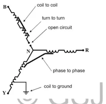
This fault is due to failure of insulation of the stator winding. It is mainly termed as inter-turn
short-circuit fault, (Gaeid & Mohamed, 2010). Different types of stator winding faults are (i)
short circuit between two turns of same phase—called turn-to-turn fault, (ii) short circuit
between two coils of same phase—called coil to coil fault, (iii) short circuit between turns of two
phases—called phase to phase fault, (iv) short circuit between turns of all three phases, (v) short
circuit between winding conductors and the stator core—called coil to ground fault, and (vi)
open-circuit fault when winding gets broken.
Different types of stator winding faults are depicted in Figure. 2.3.
Short-circuit winding fault shows up when total or a partial of the stator windings get shorted.
Open-circuit fault shows up when total or a partial of the stator windings get disconnected and no
Figure 2.3: Star-connected stator showing different types of stator winding fault
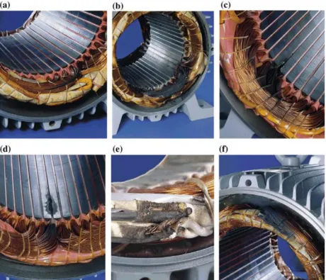
Fig. 2.5 Typical insulation damage leading to inter-turn short circuit of the stator windings in three-phase induction motors.
a. Inter-turn short circuits between turns of the same phase.
b. Winding short circuited.
c. Short circuits between winding and stator core at the end of the stator slot.
d. Short circuits between winding and stator core in the middle of the stator slot.
e. Short circuit at the leads.
f. Short circuit between phases
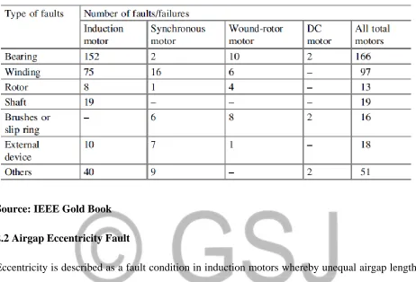
Table 2.1 Statistics on motor faults/failures
Source:IEEE Gold Book
2.2 Airgap Eccentricity Fault
Eccentricity is described as a fault condition in induction motors whereby unequal airgap length
exists along the stator to the rotor circumference. A situation of a dislocation of any one of the
three axes of rotor symmetry axis, stator symmetry axis and the rotor rotation axis from the other
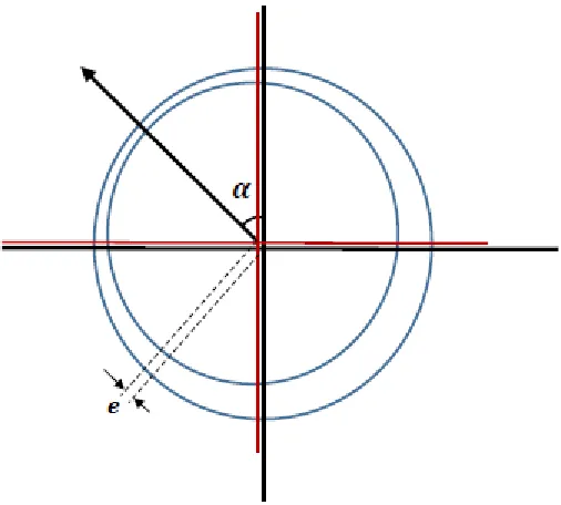
Figure 2.6: Cross section of an eccentric rotor
Source: Chuan and Shek, 2016
As depicted in Figure 2.6, the red axis is the centre axis of the rotor, the black axis is the centre
axis of the stator, and e is the movement of the rotor that causes rotor eccentricity. When the
stator symmetry axis separates from the other two axes, the minimum/maximum airgap length is
static, hence this is called static eccentricity. In contrast, if the rotor symmetry axis separates
from the other two axes and the minimum/maximum airgap length is dynamically moving then it
is dynamic eccentricity, (Faiz & Tabatabaei, 2002). Lastly, if all the three axes separate, it is
called mixed eccentricity.
The calculation of the airgap for an eccentric rotor, g`, is:
( ) ( ) (2.1)
Basic causes of eccentricity in asynchronous motors range from operation of the motor at critical
speed to wrong positioning of rotor and stator at the time of manufacturing to mechanical
axes and the rotor shaft to wear and tear of ball bearings, (Yahia et al, 2014), (Dorrell et
al,1997). All these result into adverse effects on the motor characteristics, viz:
i. Power losses increase which subsequently decreases efficiency.
ii. The temperature of the windings increases.
iii. Overall average torque decreases.
iv. Variations in speed and torque increases.
The worst debilitating effect on the motor characteristics occurs when eccentricity causes rotor to
stator rubbing which permanently damages the stator core and the rotor cage, Cardoso & Drif,
2008), (Ahmadi et al, 2013).
Notedly, airgap eccentricity comes under mechanical-related faults. Under mechanical-related
faults, there also exists broken rotor bar, mass unbalance, bearing damage, rotor winding failure
and stator winding failure.
2.3. Eccentricity Detection Techniques
2.3.1. Normalized Splitting Severity (NSS) Factor: For an induction motor with 4 poles, with
the rotating magnetic field‘s one complete rotation, two stator current cycles are produced.
Rotating magnetic field encounters with unequal air-gap with the existence of static eccentricity
within the motor. Due to magnetic reluctance, the different amplitudes of current will be
produced as compared to the ideal or healthy motor. If park transformation over a complete
rotation of stator current is drawn, it can be observed that there is a difference between two
current cycles if eccentricity fault exists in the motor. This difference can be used to detect the
If total P samples are received for two subsequent cycles of current and park‘s current idn and
iqn are found for P= 1, 2.n then normalized splitting severity factor will be given by:
( )
( )
(2.2)
Where the numerator of equation (2.2) is the difference of park‘s current for two successive
cycles and is given by:
( )
=
∑ ( ( ) ( ⁄ ⁄ )⁄
(2.3)
Now, the denominator of (2.2) is the park‘s current ‗s average length given by:
=
∑ ( ( )
(2.4)
This method has an edge over others as it is measurable, (Cardoso & Saraiva, 1992), (Park &
Hur, 2015), (Vilhekar & Ballal, 2015) and can eliminate the static eccentricity when the degree
2.3.2. Difference of area under Park's vector current for two consecutive current cycles to
the average of all the areas (APC)
For a 4-pole eccentric induction motor, if the magnitude of Park‘s vector of current is plotted for
two subsequent cycles against its angle from zero to 2π in electrical radians, then two different
curves are obtained, (Zarei & Yousefizadeh, 2014), (Onel & Benbouzid, 2008). If the difference
of average area of two given curves and the sum of area of two curves is calculated, then it can
be used as an index for detection and diagnosis of eccentricity fault, (Cardoso & Saraiva, 1993).
Research can be further expanded to detect the dynamic and mixed eccentricity. Also, the effect
of the variations in loading conditions and magnetic saturation can be determined.
2.3.3 High-Frequency Component of Stator (HFS) Current
Harmonic components in the stator current of an eccentric induction motor are given by the
following equation:
(
)
(2.5)
where the power supply‘s time harmonic order of the motor is ϑ, k is an arbitrary integer, P is the
number of pole pairs, s is the slip, is the fundamental component of supply frequency, R is
rotor slot number, is the degree of dynamic eccentricity given by 1, 2, 3, and is zero for static
eccentricity, (Thomson et al, 1997), (Barbour & Thomson, 1997), (Toliyat et al, 1996).
These harmonic components will only be produced if it is not the third multiple of fundamental
Frequency, (Barbour & Thomson, 1998), i.e. 3( ) and there exists a special relation between
There is a well-set technique to detect the given harmonics. Firstly, the stator current signal
should be sampled with a particular frequency which satisfies the Nyquist criterion, (Yahia et al,
2016). Now these sampled signals are passed through a specified filter in order to make the
amplitude of the proposed harmonics visible. Since the amplitude of these harmonics is very low
as compared to fundamental component, it is mandatory to apply the filter. Now the required
harmonic components are determined by applying Fast Fourier Transform (FFT) to the filtered
signal. This index can be well used for detection of fault as it does not show the changes when
there is an unbalance in the voltage. Also, it is precise and certain in making a difference
between static and dynamic fault.
2.3.4. Low-Frequency Components (LFS) of Stator Current
There is a drawback of the third index because it is based on high-frequency components noise
signals also interfere highly with the main signal. To detect and to separate these signals is not so
easy and requires very expensive hardware and software setup, (Nandi & Toliyat, 1998),
(Bangura & Demerdash, 2000), (Joksimovic et al, 2000). Therefore, such an index is required
which is based on low-frequency components. It is found that following harmonic components of
stator current exists in a motor with mixed eccentricity:
(2.6)
where is the fundamental frequency component of the supply, is the frequency of rotor
rotation in rotation per second (rps) and k is any random integer. The fundamental component of
can be used as an eccentricity fault index for detection of fault, (Ye et al, 2003), (Knight &
Bertani, 2005). Unlike HS it is independent of the number of rotor slots and motor‘s number of
poles. But it depends upon the presence of mixed eccentricity within the machine. It has an
advantage of comparatively easy computation and measurement, (Ebrahimi et al, 2008). But till
now the effect of unbalanced voltage, fluctuating load, magnetic saturation has not been found
out and can be considered for further experimentation.
2.3.5. Stator Current’s Low and High (SLH) Frequency Component
Both the low and high-frequency components must be found out and analyzed carefully in order
to get more accurate results for mixed eccentricity, (Nandi et al, 2002), (Thomson & Barbour,
1999). In reality, low and high-frequency components are interconnected to the presence of both
dynamic and static eccentricity stator current‘s low frequency components given by (2.6) also
create some high-frequency components given by (2.5), (Nandi & Toliyat, 2001),
(Bangura,1999), (Thomson et al, 2000). Therefore, in order to get more explicit results for mixed
eccentricity both high and low frequency must be detected and analyzed, (Thomson et al, 2000). The motor‘s number of poles and fluctuating load conditions does not cause the given fault index
which makes it advantageous. But the effect of magnetic saturation is yet to be found.
2.3.6. Ratio of summation of low-frequency stator current components and no-load current
of motor (RSN)
As stated in the fourth technique, if the machine has mixed eccentricity fault then it will generate
(2.6)
as in (2.5). Taking the value as 1 in an induction motor having 4 poles, the resultant frequencies
will come out to be approximately near to 0.5 and 1.5 named as and respectively. If
the fault index is given by:
FI =
(
2.7)where 𝐹𝐼 is fault index and is no load current. Cruz M.A and Cardoso A.J.M (Cruz &
Cardoso, 2005) reliably discovered that the value of 𝐹𝐼 comes out to be 3.8% for a healthy
motor. This is due to naturally or inherently existing static and dynamic eccentricity within the
motor. But if there is an introduction of 67% static eccentricity in the machine then the value of
𝐹𝐼 comes out to be 10.51%. Therefore, it can be well used as an index to detect eccentricity fault
in the motor. It has some other advantages of not been affected by fluctuations in load and
unbalance in voltage. But the effect of magnetic saturation of motor should be further
investigated.
2.3.7. Gyration Radius of The Torque Developed (GRT)
The measurement of the developed torque is not an easy task as some special types of sensors are
to be applied to the motor case which makes it difficult and expensive. It can be used as an index
because stator current can be used as a replacement for it, (Bangura et al, 2003), (Rajagopalan,
2007). If sampling is applied over the developed torque signals for a complete cycle and total N
Δ𝑇 = {Δτ (k), k = 2, 3, …. N}
(2.8)
where Δ𝜏( ) = 𝜏( ) − 𝜏 ( − 1) and k are the number of torque samples. If a 2D phase space
diagram is made with Δ𝜏( ) on the vertical axes and Δ𝜏 ( − 1) on the horizontal axis and is the
number of torque samples. If a 2D phase space diagram is made with on the vertical axes and on
the horizontal axes, it will show a considerable difference for eccentric motor as compared to
healthy induction motor. Therefore, it can be used as an eccentricity fault index. On the 2D
diagram, for a unit mass at any point, the mass center lies on the coordinates and for the
total diagram. These and are given by:
∑ ( )
(2.9)
∑ ( )
(2.10)
The total distance between the mass center and any point is given by 𝑑( ) as:
𝑑( ) 𝜏( ) 𝜏( ) (2.11)
Thus, the gyration radius is given as:
√
∑ ( )(2.12)
Around the mass center, there will be less concentration of the 2D diagram if the gyration radius
CHAPTER 3
MATERIALS AND METHOD
3.1 Overview of Mechanical Faults
Inductor motors convert electrical energy to mechanical energy so as to satisfy human needs in
homes, institutions (academic, churches, legal, political etc.) and in industries; agro, extractive,
manufacturing, production.
A blending machine used in homes to blend/grind pepper, tomatoes, onions, melon, spices and
grate some assorted fruits like cucumber, orange, watermelon, pine apples, apples is an induction
motor mostly a single-phase type.
Asynchronous motors are the commonest type of electrical machines used in industries in both
mild and severe setups like in grain elevators, etc.
1. Corrosion
2. Factory defects
3. Wrong placement/installation
4. Internal defects e.g. partial breakage of the interior balls
Due to the operation of induction motors, they are susceptible to mechanical faults which
metamorphosize to the eccentricity fault conditions caused by:
a. Broken rotor bars
b. Bearing faults
c. Inclination of the rotor faults
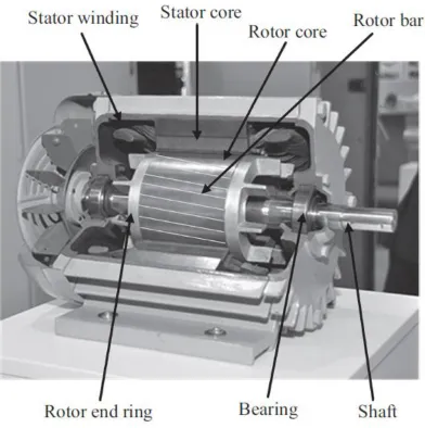
Figure 3.1: A dissected induction motor
Source: Davey, 1998
3.1.1 Broken Rotor Bars
Broken rotor bar is a mechanically-caused fault condition associated with the disjoining of the rotor bars. The application of high tension to the joints connecting the rotor bars with the end-rings within the molded or casted area result into the breakage of the bars.
Figure 3.2: Rotor broken bar fault
Source:Krause, 2013
Figure 3.3: Resistive equivalent circuitry of a healthy rotor
Source: Ceraolo & Poli, 2014
Figure 3.4 Thevenin equivalent network of a broken rotor bars
Amidst two rotor bars, the end-rings might crack, a situation largely caused by improper casting
during the manufacturing process. Worthy of note is that this fault is only possible in the squirrel
cage type of induction motors, and not in the wound induction motors. Critical attention must be
placed on the rotor bars to avoid a complete breakage of the rotor bars which most likely
degenerate into full broken bar faults and outrightly stops the flow of the bar current, (Chan &
Shi, 2011). The concise fault location (rotor circumference) also determines the degree of
severity. Number of broken bars fault does not constitute an influential factor.
Current magnitude in the rotor bars is significantly decreased if not lost hundred percent. This
happens because (Matsuo & Lipo, 1985) the armature reaction generated in a healthy rotor bar
induction motor disappears.
Summarily according to Kim S.H. and Sul S.K (Kim & Sul, 1995) the following occurs to the
circuitry elements:
i. Adjacent bars voltages increase.
ii. Total current in the adjacent bar escalates.
iii. Motor asymmetry enlarges.
Figure 3.5: Rotor broken bars magnetic field distribution
Source: Huangfu et al, 2014
Consequentially, a degenerative process emerges as illustrated in Figure 3.6 below.
Figure 3.6: Fault degeneration process under rotor broken bars
Source: Olaleye, 2019
3.1.2 Bearing Faults
During the construction process, there might be some misalignment of the bearing positioning, a
situation called bearing faults. Load misalignment during operation and shaft-axes improper
positioning could also result into the bearing fault conditions.
Mechanical
asymmetry
Electrical
distortion
Magnetic
distortion
At other times, especially during the operation of the induction motors, bearing faults result from
load improper placement, wrong placement of the shaft axes, mechanical stresses coupled with
mechanical imbalances.
3.1.3 Inclination of the rotor
Sometimes, the rotor of induction motors gets deflected at angles beyond that set by the
manufacturer, see Figure 3.7. Basically, this fault occurs as a result of the non-symmetry spread
of the induction motor airgap length along the z-axis as shown in Figure 3.7. An elongated
occurrence of this fault condition causes a prolonged intermittent movement of applied loads
which becomes grossly evident in the operation of the induction motor, (Kowalska &
Dybkowski, 2010).
Figure 3.7: Inclined rotor
Source: Dorrell et all, 2013
The major causes of this mechanical fault condition are listed below.
i. Bearing wear because of aging.
ii. Shafts bending
iii. Unstable and fluctuating mechanical loads
3.2 Healthy Induction Motors Theory, Principles & Operations
Induction motors, otherwise called asynchronous motors majorly exist in two types as below:
1. Wound rotor induction motors
2. Squirrel cage rotor induction motors
Summarily, the wound rotor has lower reliability structure in terms of mechanical stresses
compared to the squirrel cage type. Also, due to the presence of brushes connecting the rotor
winding to the output terminals in the wound rotor induction motors, electrical deterioration
easily sets in. Below table 3.1 shows the differences between the wound-rotor induction motor
and the cage-rotor induction motor.
Table 3.1 Classified differences between the two types of induction motors
Figure 3.8: Wound rotor structure
Source: Leonhard & Nordby, 1980
Figure 3.9: Squirrel cage rotor structure
Source: Nash, 1997
The cage rotor presents an easy-to-build topology which merely requires a casting process to
wound-rotor induction motor. Indeed, the cage rotor is more robust than the wound rotor which
explains why we use it in our domestic homes and not only in industries. Demand for
maintenance process is lesser for squirrel cage rotor than the wound rotor. Brushes are not
present in cage rotors which make them better choice for use.
Both types of induction motors have the stator and the rotor. The stator has the stationary parts
which support the induction motor. Also, has the magnetic circuit parts that generate the initial
magnetomotive force (MMF) at the airgap (Casadei et al, 2000), as it carries the windings of the
slots in a symmetric, sinusoidal pattern. Magnetic flux density is also produced by the windings
through proper paths of the insulated steel laminations for the purpose of reducing the magnetic
losses inside the core material, (Depenbrock, 1998). Below are the two types of magnetic losses.
a. Hysteresis losses: developed by the nonlinear magnetization phenomenon of laminations.
b. Eddy (current) losses: creates the magnetically induced electrical currents in separate
laminations, Kubota et al, 1993.
The three-phase stator windings are inserted into the slots of the stator and covered the inner
circumference of the stator by a quasi-sinusoidal spatial distribution, (Huber and Borojevic,
1995), that guarantees a less spatial harmonic distortion of the motor quantities such as current,
Figure 3.10: A 48-slot stator
Source: Bose, 1997
The magnitude of the torque developed in the induction motor is a direct function of the number
of series connected coils (solid wire or parallel stranded wires (Idris & Yatim, 2004), number
and the number of turns of each winding, Figure 3.8. Notably, an increase in the winding
resistance increases the motor torque, (Correa et al, 2007) which reduces the induction motor
efficiency. The three-phase windings employed in the stator can be star connected or delta
connected.
The quantity of voltage which can be applied to the windings highly depends on the torque
production capability of the motor and the quality of insulations. 230VD–400VY or 400VD–
690VY, (Lascu et al) are some of the most common voltage standards in industrial zones.
Induced electrical current generated in the stator to the rotor is carried by a three-phase winding
electrical current transmission in the squirrel cage wound rotor is initiated by the bars, normally
made of aluminum. For current to flow inside the rotor windings of a wound rotor type induction
motor, the rotor must have an electrically short-circuited system. The motor operation fails
anytime current cannot be induced in the rotor, (Holtz, 2006).
The only shortcoming of a cage rotor is its inability to provide an adjustable terminal resistance
required for a strong start-up of the motor, (Das, 2015). The squirrel cage rotor induction motor
is more robust against stresses because the structure is completely enclosed from the factory after
been casted and constructed, (Chikwanda & Bolton, 1993).
The torque ripple highly depends on the configuration of the windings, the number of slots and
the number of poles. The number of poles is indeed an influential factor, (Gandhi et al, 2011) in
determining the motor characteristics, particularly the supply frequency and the output speed,
(Levi et al, 2007).
Like the stator, the rotor also consists of laminations; see Figure 3.9 to reduce the magnetic (iron)
losses, (Matsuo and Lipo, 1985). The end-rings shown in Figure 3.9 play the same role as the
brushes in a wound rotor. Within the manufacturing process, both the bars and the end-rings
which are located at the two ends of the rotor are casted together simultaneously (Ito, 1981) to
have an integrated unit of rotor electric circuit.
3.3. Winding Function Modeling of Concentric Induction Motors
Electric motors being devices that convert electrical energy to mechanical energy have their
operations principled on the force which is exerted on a current carrying conductor placed in a
magnetic field. Figure 3.11 illustrates this developed force by placing a bar magnet near a
Magnetic Field and Magnetic Flux
When a current-carrying conductor is placed in a magnetic field, see Figure 3.11, it experiences a
force. Experiment shows that the magnitude of the force depends directly on the current in the
wire, and the strength of the magnetic field, and that the force is greatest when the magnetic field
is perpendicular to the conductor.
Figure 3.11: Mechanical force produced on a current-carrying wire in a magnetic field
Figure 3.12: Multi-turn cylindrical coil and pattern of magnetic flux produced by current in the coil
One obvious way to increase the flux density is to increase the current in the coil, or to add more
turns. We find that if we double the current, or the number of turns, we double the total flux,
in terms of its magnetomotive force (MMF), 𝐹 . The MMF of the coil is simply the product of
the number of turns (N) and the current (I), and is thus expressed in ampere-turns, (3.1),
𝐹
= N * I
3.1A given MMF can be obtained with a large number of turns of thin wire carrying a low current,
or a few turns of thick wire carrying a high current with the condition that the product NI is
constant, the MMF is the same.
In extension, the magnetic flux which is set up is proportional to the MMF driving it. This points
to a parallel with the electric circuit, where the current (amps) that flows is proportional to the
EMF (volts) driving it. In the electric circuit, current and EMF are related by Ohm‘s Law, which
is, Figure 3.3.ℛ
Current =
3.2
I =
3.3Equation 3.3 is a direct proportion equation. Therefore to obtain more current, the circuit
resistance must be decreased.
More applicably to a magnetic circuit, a push-back or resistance to the free flow of magnetic flux
is referred to as reluctance,ℛ . The reluctance gives invariable a measure of how difficult it is
for the magnetic flux to complete its circuit, in the same way that resistance indicates how much
opposition the current encounters in the electric circuit. This situation in magnetism is handled
with the magnetic ohm‘s law. The mathematical expression for magnetic ohm‘s law is given in
Flux =
ℛ 3.4I =
ℛ 3.5
The Airgap
It is practically impossible to put current-carrying conductors inside the iron. Therefore an
arrangement for an airgap in the magnetic circuit is ensured, as shown in Figure 3.6. Normally,
in motors, high flux density is usually used to develop force on current-carrying conductors. The
conductors on which the force is to be produced must be placed in this airgap region.
Figure 3.13: Flux lines inside low-reluctance magnetic circuit with air-gap
Figure 3.13 shows the winding distribution for one pole-pitch of the machine considered in this
model while Figure 3.12 shows the conceptual electrical diagram. Now, consider a three phase
induction motor with distributed three phase windings on the stator and three-phase windings on
the rotor as shown in Figure 1. In Figure 2, the stator windings are connected to the power
supply. It is obvious that the rotor windings must be short-circuited if the machine will start
directly from line. In both the stator and the rotor, the windings are in-phases distributed i.e. each
winding is displaced from one another by 120 degrees.
∑
(
)
3.6Where,
k = 0, 1, 2, … for phases A, B, C, … respectively,
NT = the number of turns pole per phase,
n = the harmonic order,
φ = the stator circumferential position,
pr = the number of pole pairs,
kwn = the nth harmonic winding factor
m is the number of phases.
The variable, kwn is the nth harmonic winding factor which can be calculated with:
( )
( )
(
)
3.7Where,
kdn = distribution factor
kpn = pitch factors,
q = the number of slots per pole per phase,
τp = the pole pitch
W = the coil width.
For simplicity, we will consider only the fundamental component of the windings and then
(
)
3.8
(
)
3.9
(
)
3.10
It is obvious from equations 3.8 to 3.10 that Ns is the amplitude of the fundamental component of
the magnetomotive force waveform for the stator windings, the subscripts R, Y, and B relate
directly to the phases R, Y and B.
Similarly, the rotor winding functions will be:
( ) 3.11
( ) 3.12
( )
Here, ϴr is the rotor circumferential position, known as rotor position.
3.4. Voltage Equation Modeling of Concentric Induction Motors
By induction process, electrical energy generated in the stator flows to the rotor of induction
motors. The combination of the energy generated in the stator, Es and that of the rotor, Er, gives
the input energy. However, because of the rotation of the rotor, the two-energy change with
respect to time. Thus, we have the input energy change, 𝑑 equals to the sum of the energy
𝑑 𝑑 𝑑 3.14
Likewise, the electrical power fed into three phase induction motors are the red (R-phase) phase,
the yellow (Y-phase) phase and the blue (B-phase) phase displaced from each other by 120
( ⁄ 𝑑 ) degrees respectively. Illustrating this with an equivalent circuit in Figure 3.14,
Figure 3.14:‘Exact’ per-phase equivalent circuit of induction motor.
Source:
NB: The secondary (rotor) parameters have been referred to the primary (stator) side
Borrowing a leave from Kirchoff‘s voltage law, we have the same form of voltage equations
developed across each of the winding,
𝐼
( 𝐼)
3.15
Magnetic energy losses here are assumed to be zero. The energy unit is Joules (J). The electrical
energy generated is the electromotive force, EMF ( ), a time-dependent variation of the
product of voltage ( ) and current (𝐼).
𝐼 3.16
3.17
Removing dt from the LHS, we have,
𝑑 𝑑 3.18
Since there are now two 𝑑 on the RHS, integration sets in.
Therefore, the electromotive force for the stator and rotor obtained below.
For the stator component, we have the EMF, as:
𝑑 𝐼 𝑑 3.19
Similarly, for the rotor, the EMF ( ) we have,
𝑑 𝐼 𝑑 3.20
From Ohm‘s law,
V = I. R 3.21
Substituting 3.7 into 3.5, we have,
𝑑 𝐼 𝐼 𝑑 3.22
Likewise, on the rotor side,
On substitution of equations 3.22 & 3.23 into equation 3.14, we obtain,
d = 𝐼 𝐼 𝑑 + 𝐼 𝐼 𝑑 3.24
Using the 3 phases (R, Y & B) for a normal power transmission line,
We obtain, on using equation 3.22, for the stator windings:
On the R line, we have,
𝑑 = 𝐼 𝐼 𝑑 + 𝐼 𝐼 𝑑 3.25
On the Y phase, we have,
𝑑 = 𝐼 𝐼 𝑑 + 𝐼 𝐼 𝑑 3.26
On the B winding, we obtain,
d = 𝐼 𝐼 𝑑 + 𝐼 𝐼 𝑑 3.27
Therefore, mathematics of matrix comes in because each of the 3 phases (R, Y & B) play a role.
As a result, for the stator windings, the composite resistive components matrix is,
[ ] 3.28
Working from first principle, the individual phase (R, Y & B), are:
On the R phase, we have,
𝑑 = 𝐼 𝐼 𝑑 + 𝐼 𝐼 𝑑 3.29
On the Y phase, we have,
𝑑 = 𝐼 𝐼 𝑑 + 𝐼 𝐼 𝑑 3.30
On the B winding, we obtain,
d = 𝐼 𝐼 𝑑 + 𝐼 𝐼 𝑑 3.31
Thus, the effective composite matrix resistance on rotor windings is,
[ ] 3.32
Effectively combining equations 3.28 (stator end) and 3.32 (rotor circuit), we have the composite
matrix of 6 by 6 of which each winding resistance dominates a whole row and column, i.e.,
[
( )
( )
]
3.33
𝑑 3.34
3.5 Modeling Entire Circuitry Voltage Equation for A Concentric Induction Motor
The developed voltage equation of 3.15 of the three-phase induction motor under study is a
differential equation.
Recalling,
𝐼
( 𝐼)
3.15
Thus, calculus, integration concisely must be used to obtain its solution. With the solution, the
value for the propagating current can be determined. If we recall that the inductance L is a
function of rotor position (on account of the stator-rotor mutual inductance), one can re-write
equation 3.15 as:
𝐼 ( )𝑑𝐼 𝑑 𝐼
𝑑
𝑑 ( ( ))
But we know that . and if one can further identify as speed ω, we can rewrite
equation 3.35 as:
𝐼 ( )𝑑𝐼 𝑑 𝐼
𝑑
𝑑 ( ( ))
Finally, if we make subject of formula in 3.36 we will have:
Equation 3.37 shows that to calculate
at every time step, the derivative of the six by six
inductance matrix and its inverse needs to be calculated prior to determining the algebra of 3.36.
This is a very cumbersome exercise in view of the usual minuteness of time variation for which
such calculations have to be performed in order to yield a very accurate solution. However, this
is the price to be paid for discarding the popular dimensionless d-q model in favour of this
dimension-based phase variable model
3.6 Modeling Electromagnetic Torque Equations for a Concentric Induction Motor
The torque is generated from the position-dependent mechanical energy changing which is
applied to the rotor via the airgap. Achieving this necessitates the combination of equations 3.33,
3.34, 3.35 with 3.42 coupled with equation 3.43.
A thorough comprehension of the working principle of induction motors reveals that an
induction motor is basically an electric machine that converts electrical energy to mechanical
energy. En route this conversion process, electromagnetic force is developed across the
windings: of both stator and rotor. This generated electromagnetic force serves to couple the
electrical energy with mechanical energy. Therefore, the torque is determined by the
instantaneous power transferred in the electromechanical system.
Recalling them,
d = 𝐼 𝐼 𝑑 + 𝐼 𝐼 𝑑 3.25
And, due to the generated flux,
d = 𝐼 . 𝑑 + 𝐼 d 3.38
[ ] [ ] = [ ] [ 𝐼 𝐼 𝐼 ] + [ ( ) ( ) ( ) ( ) ( ) ( ) ] [ 𝐼 𝐼
𝐼 ] 3.40
[ ] [ ] = [ ] [ 𝐼 𝐼 𝐼 ] + [ ( ) ( ) ( ) ( ) ( ) ( ) ] [ 𝐼 𝐼
𝐼 ] 3.41
The Magnetic Co-energy:
From basic magnetism, energy is stored in the magnetic circuits: the stator and rotor windings.
This energy is called the magnetic co-energy, Emco
The magnetic co-energy is the source that generates the electromagnetic torque, Temg
Therefore, the electromagnetic torque, Temg is mathematically established as,
𝑇
*
+
( 3.42Where:
𝑇 = electromagnetic torque
= magnetic co-energy
However, the induction machine mechanical energy combines as a relationship among the rotor
mechanical angle , the angular speed of the rotor , the rotor load inertia and of
course the load torque .
Mathematically, we have,
+
𝑇
𝑇
3.43The total combination of all the energies stored inside the stator and the rotor windings due to
self and mutual inductance make up the induction motor‘s magnetic co-energy. See below:
Stator Windings magnetic co-energy:
𝐼
𝐼
𝐼
3.44Rotor Windings magnetic co-energy:
𝐼
𝐼
𝐼
3.45Therefore, the overall developed magnetic co-energy is the addition of equations 3.46 and 3.47
3.6.1 Phase Variable Modeling of Electromagnetic Torque Equations of a Concentric
Induction Motor
From the co-energy as postulated by (4), a 3-phase induction machine has its torque
mathematically represented as,
𝑇 𝐼 ( )
𝐼 3.47
With the inductance of the three-phase induction machine based on the rotor phase angle, , the
stator – rotor inductance equates to the rotor stator inductance, i.e.
Lsr = Lsr 3.48
It is at the state of equation 29 above, that torque is generated.
At torque production, the current flowing in the rotor is the same as the flowing current in the
stator, i.e.
𝐼 = 𝐼 3.49
Therefore on substitution of equations 29 and 30 into equation 28, we have the
three-phase asynchronous motor torque as,
𝐼 = 𝐼 𝐼 3.50
But from matrix algebra,
𝐼
=
𝐼
𝐼
𝐼
3.51
Likewise on the rotor windings,
𝐼 = 𝐼 𝐼 𝐼 3.52
Due to the electromagnetic torque production, the phase variable inductance is,
Lsr [ r ] 3.56
The
The rotational part of the 3-phase asynchronous motor develops a mechanical
energy. This is representable mathematically as,
3.57
Where,
L
sr= the load torque
= the inertia of IM
= the angular velocity
The stator to mutual inductance matrix is a differential calculus equation. This is a
very vital requirement to evaluate the dynamism of the torque.
[
]
3.58
=
[
(
)
(
) (
)
(
)
(
)
(
)
(
) (
)
(
)
]
3.59
3.6 Flux Equations Modeling of a Concentric Induction Motor
Magnetic flux is a measurement of the total magnetic field which passes through a given area,
(our induction motor in this context). It is a useful tool for helping describe the effects of the
magnetic force on something occupying a given area. The measurement of magnetic flux is tied
to a particular area, stator windings and rotor windings here.
If we use the field-line picture of a magnetic field, then every field line passing through the given
area contributes some magnetic flux. The angle at which the field line intersects the area is also
important. A field line passing through at a glancing angle will only contribute a small
component of the field to the magnetic flux.
Recall, these 5 equations that we must integrate:
𝑑 𝑑 𝑑 3.1
𝑑 𝐼 𝑑 3.5
𝑑 𝐼 𝑑 3.6
d = 𝐼 𝐼 𝑑 + 𝐼 𝐼 𝑑 3.17
Accordingly, integration of these 5 equations produces respectively:
3.1> ∫ 𝑑 = ∫ 𝑑 ∫ .dt 3.60
3.5> ∫ 𝑑 ∫ 𝐼 𝑑 .dt 3.61
3-6> ∫ 𝑑 ∫ 𝐼 𝑑 .dt 3.62
3.17> ∫ 𝑑 = ∫ 𝐼 𝐼 𝑑 𝑑 + ∫ 𝐼 𝐼 𝑑 . dt 3.63
3.19> ∫ 𝑑 ∫ 𝑑 ∫ .dt 3.64
3.6.1 Faraday’s law
This applies precisely since we are here to model the flux equations:
Now, Faraday‘s law states that the rate of change of magnetic flux through a closed coil (or wire)
is proportional to the electromotive force developed (techtarget.com).
Mathematically, Faraday‘s law says,
∫ 3.65
∫ 𝑑 ∫ 𝑑 3.66
Applying equation 3.29 to 3.17, we obtain,
d = 𝐼 𝐼 𝑑 + 𝐼 𝐼 𝑑 3.17
The rate of change of the developed magnetic flux through the 2 windings gives
= magnetic flux
Therefore, the magnetic flux generated across the stator windings is
d = 𝐼 𝑑 3.67
Since the magnetic flux is not static but dynamic as it changes along the windings (stator &
rotor). We must then differentiate,
Effectively therefore, equation 3.27 becomes,
= 𝐼 𝑑 3.68
Integrating, the LHS, we have:
∫ 𝑑 ∫ 𝐼 dt. dt 3.69
Resulting into,
𝐼 3.70
dt. dt = unity 3.71
Hence, the magnetic flux on the stator windings is
d = 𝐼 𝑑 3.72
On the rotor, it is:
d = 𝐼 𝑑 3.73
And, with earlier cited Faraday‘s law,
We obtain,
d = 𝐼 𝐼 𝑑 + 𝐼 𝐼 𝑑 3.74
As the electrical energy supplied into the windings (stator & rotor) is wholly converted to
magnetizing energy and mechanical energy,
We therefore obtain the differential form of Faraday‘s law:
d = 𝐼 . 𝑑 + 𝐼 d 3.75
Practically, an induction motor has magnetic flux variation on both the stator windings and the
rotor windings.
Thus,
On the stator side, we obtain the flux linkage gradient as:
= 𝐼 3.76
In the same vein, the rotor flux linkage is:
= 𝐼 3.77
There are two distinct types of stator & rotor fluxes (mutual & leakage fluxes, see Figure 3.15
Precisely, the leakage flux is the additional magnetic and electrical losses causing a rise in the
hotness of the induction motor components.
Figure 3.15: Induction motors mutual and leakage fluxes Source: Casadei et al, 2015
3.6.2.1Mutual Flux Explained
This is the magnetic flux developed as a result of the mutual relationship between the stator
windings and the rotor phases, Figure 3.15. Concisely speaking, the mutual flux is the unique
part of the flux that guarantees the coupling of stator and rotor components which eventually
develops into the electromagnetic torque.
This is the flux that transforms power or energy from the primary winding (the stator) to the