Volume 2009, Article ID 724947,10pages doi:10.1155/2009/724947
Research Article
Model-Based Hand Tracking by Chamfer Distance and
Adaptive Color Learning Using Particle Filter
Chutisant Kerdvibulvech and Hideo Saito
Department of Information and Computer Science, Keio University, 3-14-1 Hiyoshi, Kohoku-ku 223-8522, Japan
Correspondence should be addressed to Chutisant Kerdvibulvech,[email protected]
Received 31 January 2009; Revised 23 June 2009; Accepted 3 October 2009
Recommended by Amit Roy-Chowdhury
We propose a new model-based hand tracking method for recovering of three-dimensional hand motion from an image sequence. We first build a three-dimensional hand model using truncated quadrics. The degrees of freedom (DOF) for each joint correspond to the DOF of a real hand. This feature extraction is performed by using the Chamfer Distance function for the edge likelihood. The silhouette likelihood is performed by using a Bayesian classifier and the online adaptation of skin color probabilities. Therefore, it is to effectively deal with any illumination changes. Particle filtering is used to track the hand by predicting the next state of three-dimensional hand model. By using these techniques, this method adds the useful ability of automatic recovery from tracking failures. This method can also be used to track the guitarist’s hand.
Copyright © 2009 C. Kerdvibulvech and H. Saito. This is an open access article distributed under the Creative Commons Attribution License, which permits unrestricted use, distribution, and reproduction in any medium, provided the original work is properly cited.
1. Introduction
Acoustic guitars are currently very popular and as a conse-quence, research about guitars is a popular topic in the field of computer vision for musical applications.
Maki-Patola et al. [1] proposed a system called “Virtual Air Guitar” using computer vision. Their aim was to create a virtual air guitar which does not require a real guitar but produces music similar to a player using a real guitar. Liarokapis [2] proposed an augmented reality system for guitar learners. The aim of his work is to show the augmentation (e.g., the positions where the learner should place the fingers to play the correct chords) on an electric guitar as a guide for the novice player. Motokawa and Saito [3] built a system called “Online Guitar Tracking” that supports a guitarist by using augmented reality. This is done by showing a virtual model of the fingers on a stringed guitar as a teaching aid for anyone learning how to play the guitar.
These systems do not aim to detect the fingering and handing which a player is actually using (a pair of gloves are tracked in [1], and graphics information is overlaid on captured video in [2] and [3]). We have developed a different approach from most of these researches.
In our previous work [4], we proposed a method that accurately locates the positions of the fingertips of a guitar player by employing computer vision aid. However, it cannot track the whole structure of guitarist’s hand. In order to improve the previous work, we present a model-based hand tracking which will be further applied to the recovery of three-dimensional hand motion of guitar player from an image sequence, without the use of markers. Example input and output images are given inFigure 1.
A challenge for tracking the hand of a guitar player is that, while playing the guitar, the fingers are not stretched out separately. Thus the existing model-based hand tracking methods such as [5], [6], and [7] are not directly applicable to the guitarist’s hand tracking as the fingers are usually bent while playing the guitar. Moreover, the background is dynamic and nonuniform (e.g., guitar neck and natural scene) which makes it more difficult for background segmen-tation. Also, for many classic guitars, the colors of frets and strings are very similar to skin color. As a result it is not an easy task to track the hand correctly.
(a)
(b)
Figure1: Model-based guitarist’s hand tracking: (a) sample input image and (b) sample output image (projected corresponding three-dimensional hand model).
hierarchical model with 27 degrees of freedom (DOF) is used. The DOF for each joint correspond to the DOF of a real hand. Then we extract corresponding features (edges and silhouette) between three-dimensional hand model and input image. The Canny edge detection is used to extract the edge. Then, the Chamfer Distance function [10] is used for edge likelihood. The silhouette is determined by using a Bayesian classifier and the online adaptation of skin color probabilities [11,12]. By using the online adaptation, this method is able to cope well with illumination changes. Following this, the particle filter [13] is applied to track the hand by predicting the next state of three-dimensional hand model. As a result, the system enables us to visually track the hand, which can be applied to track the hand of a guitarist.
The advantage of particle filter is that the tracker is able to initialize and recover. Particle filter uses a lot of state vectors (particles) to represent possible solution in each time instance. If the hand moves fast until lost tracks, it can automatically recover from tracking failures. Also, in [9] they use template-based method. In their work, the range of allowed hand motion is limited by the number of templates that need to be stored. Thus, their method requires creating many templates manually enough at the first time, unless its coverage will not be sufficient for hand’s movements. In contrast, by applying particle filter, it can avoid the cumbersome process of manually generating a lot of templates.
The work that is similar to ours is by De la Gorce et al. [14] They focused on recovery of geometric and photometric pose parameters of a skinned hand model from monocular image sequences. However, they do not aim to apply hand model-based to track the hand of guitarist which includes with guitar neck in the background. In their work, their
Input image 3D hand model
Feature extraction of input image
Feature extraction of 3D hand model
Particle filter tracking Figure2: Method overview.
assumption is that the background image is basically static and was also obtained from a frame where the hand was not visible. In other words, when they define the image synthesis process, they assume that the background image is known (if their background is not static, they relax this constraint by assuming that the color distribution associated to the background is available). In the case of guitarist’s hand tracking, the background is dynamic because the guitar neck is not fixed to the camera which makes the situation different. Due to the dynamic movement of guitar position, it cannot simply use background subtraction from a frame where the hand is invisible at the first time. In addition, for many classic guitars, the colors of frets and strings are similar to skin color which makes it difficult for segmenting the hand from the guitar neck. The method of robust hand segmentation from the guitar neck is undoubtedly needed. For this reason, in this paper we apply a Bayesian classifier and the online adaptation of skin color probabilities [11,12] to robustly segment the hand region from the guitar neck. This approach can also deal well with illumination changes.
2. Method
Figure 2 shows the schematic of the implementation. We firstly build the three-dimensional hand model using trun-cated quadrics. Following this, the feature extraction algo-rithm is performed for the hand model. At the same time, we also extract the feature of captured image. As the next step, we utilize a particle filter to track the hand.
2.1. Construct 3D Hand Model. This section explains the method we used for building the hand model [8,15]. The hand model is constructed using a set of quadrics {Qi}
NQ
i=1,
approximately representing the anatomy of a real human hand, as represented inFigure 3. The 27 DOF hand model is constructed from 39 truncated quadrics. A hierarchical model with 27 DOF is used: 6 for the global hand position, 4 for the pose of each finger, and 5 for the pose of the thumb [16]. Starting from the palm and ending at the tips, the coordinate system of each quadric is defined relative to the previous one in the hierarchy.
(a)
(b)
Figure3: Our geometric hand model, built by a set of quadrics and drawn by OpenGL.
0 θ
r
w ys1
ys0
90◦
Figure4: Building a finger model from quadrics. The joints are modeled with spheres. This shows a view of bottom joint [8].
that can be easily obtained, such as the height, width, and depth of a finger. These values are then used to set the parameters of the quadrics. Each finger is built from cone segments and truncated spheres, as shown inFigure 4. The width parameterwof the cone is uniquely determined by the height of the segmenthand the radiusrof the sphere, which models the bottom joint:
w=√ hr
h2−r2. (1)
In order to create a continuous surface, the parameterys1
of the bottom clipping plane for the sphere is found as
ys
1=
r2
h, (2)
and from this the clipping parameters for the cone are found as
yc
1=h−y1s,
yc
0=yc1−f1H,
(3)
whereHis the sum of the length of all three cone segments, andf1is the ratio between the length of the bottom segment
to the total length.
2.2. Feature Extraction. This section explains the feature extraction which is used within the algorithm. The methods explained in this section are applied for both the hand model image and the captured image. The likelihood p(z|x) relates observations z in the image to the unknown state x. The likelihoods we used are based on the edge mapzedge of the
image (edge) as well as pixel color values zsil (silhouette).
These features have proved useful for detecting and tracking hands in previous work [17]. Therefore, the joint likelihood ofz=(zedge,zsil)Tis approximated as
p(zx)=pzedge,zsilx,
pzedge,zsilx≈pzedgexpzcolx.
(4)
2.2.1. Edge Likelihood. We first extract feature by considering the edge likelihood. The edge likelihood termp(z(edge)|x) is
based on the chamfer distance function [10]. Given the set of template pointsA= {ai}Ni=a1and the set of Canny edge points
B = {bi}Ni=b1, a quadratic chamfer distance function is given
by the average of the squared distances between each point of A and its closest point in B:
d(A,B)= 1
Na
a∈A
min
b∈Ba−b
2. (5)
Example edge extraction is shown in Figure 5. The chamfer function can be computed efficiently for many model templates by using a distance transform (DT) of the edge image. This transformation takes the set of feature pointsBas input and assigns each location the distance to its nearest feature; that is, the DT value at locationucontains the value min
b∈Bu−b. The chamfer function for a single template
can be computed by correlating its points with the DT image. Given the shape templatePand the observed edge image
zedge, the likelihood function is defined as
pzedge|x = 1
Zexp
−λdA(x),Bzedge, (6)
whereA(x) denotes the set of template points.Ais generated by projecting the model using the state vectorx, andBis the set of edge points obtained from the edge imagezedge. In our
(a)
(b)
Figure5: Edge extraction: (a) input image and (b) edge extraction result by Canny edge detector.
2.2.2. Silhouette Likelihood. We also perform feature extrac-tion by determining the silhouette likelihood. The silhouette is calculated by using a Bayesian classifier and the online adaptation of skin color probabilities [11,12].
The learning process has two phases. In the first phase, the color probability is obtained from a small number of training images during an offline preprocess. In the second phase, we gradually update the probability automatically and adaptively from the additional training data images. The adapting process can be disabled as soon as the achieved training is deemed sufficient.
Therefore, this method allows us to get accurate color probability of the skin from only a small set of manually prepared training images. This is because the additional skin region does not need to be segmented manually. Also, because of the adaptive learning, it can be used robustly with changing illumination during the online operation.
In this way, because our method can learn color probabil-ity of hand adaptively, the background of testing images does not have to be the same. When the background is suddenly changed, the segmentation result might become error prone in the beginning but as soon as several frames are learned adaptively, the segmentation will be recovered and becomes good again.
Learning from Training Data Set. During an offline phase, a small set of training input images (20 images) is selected on which a human operator manually segments skin regions. The color representation used in this process is YUV 4 : 2 : 2 [18]. However, the Y-component of this representation is not employed for two reasons. Firstly, the Y-component corresponds to the illumination of an image pixel. By omitting this component, the developed classifier becomes less sensitive to illumination changes. Secondly, compared to
a 3D color representation (YUV), a 2D color representation (UV) is lower in dimensions and, therefore, less demanding in terms of memory storage and processing costs.
Assuming that image pixels with coordinates(x,y)have color valuesc = c(x,y), training data are used to calculate the following.
(i) The prior probability P(s) of having skinscolor in an image. This is the ratio of the skin-colored pixels in the training set to the total number of pixels of whole training images.
(ii) The prior probabilityP(c) of the occurrence of each color in an image. This is computed as the ratio of the number of occurrences of each colorc to the total number of image points in the training set.
(iii) The conditional probability P(c | s) of a skin being colorc. This is defined as the ratio of the number of occurrences of a colorcwithin the skin-colored areas to the number of skin-colored image points in the training set.
By employing Bayes’ rule, the probabilityP(s | c) of a colorcbeing a skin color can be computed by using
P(s|c)=P(c|s)P(s)
P(c) . (7) This equation determines the probability of a certain image pixel being skin-colored using a lookup table indexed with the pixel’s color. The resultant probability map thresh-olds are then set to be thresholdTmax and threshold Tmin,
where all pixels with probability P(s | c) > Tmax are
considered as being skin-colored—these pixels constitute seeds of potential skin-colored blobs—and image pixels with probabilities P(s | c) > Tmin where Tmin < Tmax are
the neighbors of skin-colored image pixels being recursively added to each color blob. The rationale behind this region growing operation is that an image pixel with relatively low probability of being skin-colored should be considered as a neighbor of an image pixel with high probability of being skin-colored. The values forTmaxandTminshould be
determined by test experiments (we use 0.5 and 0.15, resp., in the experiment in this paper). A standard connected com-ponent labelling algorithm (i.e., depth-first search) is then responsible for assigning different labels to the image pixels of different blobs. Size filtering on the derived connected components is also performed to eliminate small isolated blobs that are attributed to noise and do not correspond to interesting skin-colored regions. Each of the remaining connected components corresponds to a skin-colored blob.
(a)
(b)
Figure6: Hand extraction by silhouette likelihood: (a) input image and (b) hand extraction result by adaptive skin color learning.
pixels is required. To solve this problem, skin color detection maintains two sets of prior probabilities. The first set consists ofP(s),P(c), andP(c |s) that have been computed offline from the training set. The second is made up ofPW(s),PW(c), and PW(c|s) corresponding to the P(s), P(c), and P(c|s) that the system gathers during the W most recent frames respectively. Obviously, the second set better reflects the “recent” appearance of skin-colored objects and is therefore better adapted to the current illumination conditions. Skin color detection is then performed based on the following weighted moving average formula:
PA(s|c)=γP(s|c) +
1−γPW(s|c), (8) whereγis a sensitivity parameter that controls the influence of the training set in the detection process, PA(s | c) represents the adapted probability of a colorc being a skin color, and P(s | c) and PW(s | c) are both given by (1) but involve prior probabilities that have been computed from the whole training set (for P(s | c)) and from the detection results in the lastWframes (forPW(s|c)). In our implementation, we setγ=0.8 andW=5.
Thus, the hand skin color probability can be determined adaptively. By using online adaptation of skin color probabil-ities, the classifier is easily able to cope with considerable illu-mination changes. Example hand segmentation is illustrated inFigure 6.
In this way, given the shape templatePand the observed silhouette image zsil, the likelihood function p(zsil | x)
is defined from the ratio difference of overlapped areas, calculated from adaptive hand segmentation algorithm.
The skin color (or the luminance) in the testing images does not have to be similar to the skin color in the training images. This is because during online process we can learn the input color adaptively, so that the skin color probability
will converge automatically. In case that the skin color (or the luminance) is suddenly changed, the segmentation result might become error prone in the beginning but as soon as several frames are learned, and the segmentation will be recovered. In other words, the training images are just the initial value (seed). When the real input hand enters the scene, the probability will converge automatically to the new values matching with the real hand.
2.3. Particle Filter Tracking. Particle filtering [13] is a useful tool to track objects in a clutter, with the advantage of performing automatic recovering from tracking failures. We apply particle filter to compute and track the hand. In our method, one particle represents each DOF of hand model. We determine the probability-density function by calculating from edge likelihood and silhouette likelihood, as explained inSection 2.2.1andSection 2.2.2, respectively. The calculation is based on the following analysis.
Given that the process at each time-step is an iteration of factored sampling, the output of an iteration will be a weighted, time-stamped sample-set, denoted by {s(tn),n = 1,. . .,N}with weightsπt(n), representing approximately the probability-density functionp(Xt) at time t, whereNis the size of sample sets,s(tn)is defined as the position of thenth particle at time t, and Xt represents the position of hand model at time.
The iterative process can be divided into three main stages:
(i) selection stage, (ii) predictive state, (iii) measurement stage.
In the first stage (the selection stage), a sample st(n) is chosen from the sample-set{s(tn−)1,πt(−n)1,c(tn−)1}with
probabil-itiesπt(−j)1, wherec (n)
t−1is the cumulative weight. This is done
by generating a uniformly distributed random numberr ∈
[0, 1]. We find the smallestjfor whichc(t−j)1≥rusing binary
search, and thenst(n)can be set as follows:st(n)=s
(j)
t−1.
Each element chosen from the new set is now subjected to the second stage (the predictive step). We propagate each sample from the setst−1by a propagation function, g(s(
n)
t ), using
s(tn)=g
st(n)
+ noise, (9)
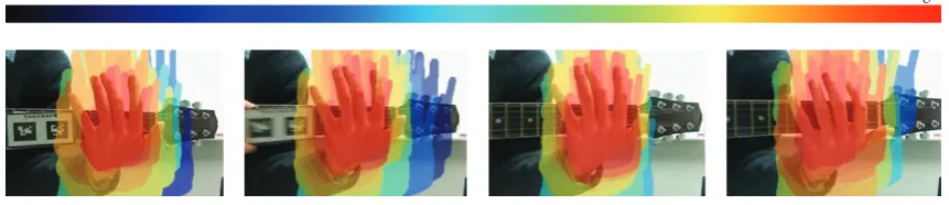
Low High
Figure7: Particle filter behaviour in our system.
frame. In this way, we use only the noise information by definingg(x)=xin (9).
In the last stage (the measurement stage), we generate weights from the probability-density function p(Xt) to obtain the sample-set representation {(s(tn),πt(n))} of the state-density for timetusing
πt(n)=p
Xt=s(tn)
=p(z|x), (10)
wherep(z|x) is the joint likelihood ofz, obtained from (4). Next, we update the cumulative probability, which can be calculated from normalized weights using
ct(0)=0, c(tn)=ct(n−1)+πt(n)Total, (11)
whereπt(n)Totalis the total weight andn=1,. . .,N.
Once theNsamples have been constructed, we estimate moments of the tracked hand model at time-steptas using
εf(Xt)=ΣN n=1π
(n)
t s(tn). (12) The hand can then be tracked, enabling us to perform automatic track recovering.
Figure 7shows how the particle filter visually behaves in our system. The color in these hand model images illustrates the probabilities of the hand which is used in the particle filter step (left-to-right means low-to-high probability in color scale). For example, at each moment if the particle has a low normalized probability of being the correct hand pose by considering edge and silhouette likelihoods as described in
Section 2.2, the color of the hand model shown will be black. In contrast, if the particle has high probability of the hand, the color will be red. The sum over all probabilities of every particle is 1. The scale of color used is also shown inFigure 7. If the tracking certainty is lower than the threshold we set, it will return to the initial state again (as described in Particle Filter Tracking). This means that the particles will be initially distributed again for tracking. Thus, if the recent tracking results are not perfect, the hand can still be tracked.
3. Results
Representative results from our experiments are shown in this section.Figure 8provides some representative results of
the tracking experiments from a single camera with captured resolution 320×240 pixels. The reported experiment was acquired and processed on an Intel(R) Core (TM2) Duo CPU T7300 laptop computer running MS Windows at 2.0 GHz 778 MHz. One thousand particles are used for each experiment, that is,N=1000. The execution time for these sequences is about 84 seconds per frame.
It is possible to use all 27 DOF in tracking, but it will take too long time to compute the result in each frame (a lot of particles are required for tracking in those high dimensions). Thus, in our experiments we limit the movement of the hand in the input video to a small number of DOF. Then, we track the hand movement in this reduced dimension.
Figures 8 (a) and (b) show the results of tracking global hand motion together with finger articulation. The images are shown with projected corresponding three-dimensional hand models (green color). For these sequences, the three-dimensional hand model has 11 DOF.
As seen in Figure 8 (a), at the commencement of the experiment, the hand starts moving from left-to-right and then moving back from right-to-left, respectively. It can be seen that the global hand motions are tracked successfully in this sequence.
Figure 8 (b) shows the result of hand tracking, when bending down the forefinger toward the palm. For this sequence, the range of global hand motion is restricted to a smaller region, but it still has 11 DOF. It can be observed that the proposed tracker successfully recovers these motions.
(a) Results of hand tracking, when moving the global position of hand (11-DOF model)
(b) Results of hand tracking, when bending the forefinger down toward the palm (11-DOF model) Figure8: Representative results of 3D model-based hand tracking.
(a) Results of hand tracking, while holding the guitar (13-DOF model) without adaptive color learning
Table1: Error performance in terms of fingertip localization measured against manually labeled ground truth with different numbers of particles.
Number of particles Execution time (seconds per frame) Mean distance errors (pixels)
750 69 11.78
1000 84 8.46
1250 126 6.18
(a) (b) (c)
Figure10: Results of hand tracking, when there is more than one hand or other skin areas rather than hand in the scene (13-DOF model).
(a) (b) (c)
Figure11: Results of hand tracking, when the scale of hand changes (13-DOF model).
Camera is calibrated, so that the intrinsic parameters are known before starting the system. Then the camera is registered to the world coordinate through ARTag (Aug-mented Reality Tag) [19]. Hence, when the projection matrix is known, we can track by using particle filter to register to the three-dimensional hand models onto the input images. It converges to the hand automatically by fitting model based on silhouette and edge clues using particle filter. Because ARTag’s marker is placed to the guitar neck, the origin of the world coordinate is defined on the guitar neck. In this way, we know the projection matrix of camera at every frame, and so we can track the three-dimensional hand model using the proposed method.
In our method, we assume that the biggest region of a skin color found in the images is a hand blob. When we segment the skin area from the images, we remove small noise by size filtering. We determine that if noise is smaller than the threshold, we remove it. After that, we choose the
biggest area as a hand blob. Therefore, our assumption is that the hand region has to be the largest area of skin found in the images. In this way, even though there is some other regions with color similar to skin color appear in the scene, our method can deal with. Similarly, if there is more than one hand or having faces in the images (but the hand of interest is the biggest skin area), the hand can still be tracked.
Figure 10shows representative results when there is more than one hand or other skin area rather than hand in the image. As described, if there is more than one skin area in the image, our assumption is that the biggest area of a skin color is a hand blob. Thus, although there are other areas of skin color, we can differentiate them by deciding the size of appearing skin-color areas.
hands changes (i.e., Z-axis is changed), our system can still track the hand correctly.
Because it is difficult to measure directly the ground truths of the parameters of every joint of 3D hand model, we evaluate the error performance by measuring the projection of fingertips in 2D. Table 1 shows the error performance in terms of fingertip localization of five fingers measured against manually labeled ground truth with different num-bers of used particles. We randomly select 25 images from 200 images from the sequence to measure the error performance. We measure the distance errors by measuring the differences of the distance between the ground truth positions and the results of fingers tracking positions in each fingertip. We obtain the ground truth positions manually by human eyes to locate the correct positions of five fingertips, while the fingertips of tracked hand model are estimated by our system at each time. The distance errors in each fingertip are measured by Euclidean distances in pixels (320×240 total image size) with respect to the ground truth positions. After obtaining the distance errors from five fingertips, we calculate the mean of the distance errors, as shown inTable 1. The execution time in each of the number of used particles is also shown in seconds per frame. We believe that these errors are low enough to make the proposed algorithm presented in this paper a suitable method for guitarist’s hand tracking.
4. Conclusions
In this paper, we have developed a system that tracks the hand by using a model-based approach. We construct the three-dimensional hand model by using a set of quadrics. After that, we utilize a quadratic chamfer distance function to calculate the edge likelihood, and then the online color learning adaptation is utilized. Following this, particle filter is performed to track the hand. This implementation can be used to further improve the hand tracking application of guitarist such as [20]. Although we believe that we can successfully produce accurate output from our system, the current system has the limitation with finger occlusion and guitar neck occlusion. This sometimes happens when playing the guitar in real life. Another limitation is about the high dimension of the state space (DOF). The number of particles required increases with the dimension of the state space. Therefore, some improvement or optimization should be considered to make the system faster. In the future, we intend to further refine these problems.
Acknowledgments
This work is supported in part by a Grant-in-Aid for the Global Center of Excellence for High-Level Global Cooperation for Leading-Edge Platform on Access Spaces from the Ministry of Education, Culture, Sport, Science, and Technology in Japan. The work presented in this paper is partially supported by CREST, JST (Research Area: Foundation of technology supporting the creation of digital media contents).
References
[1] T. Maki-Patola, J. Laitinen, A. Kanerva, and T. Takala, “Experiments with virtual reality instruments,” inProceedings of the International Conference on New Interfaces for Musical Expression (NIME ’05), pp. 11–16, Vancouver, Canada, May 2005.
[2] F. Liarokapis, “Augmented reality scenarios for guitar learn-ing,” inProceedings of the International Conference on Euro-graphics UK Theory and Practice of Computer Graphics, pp. 163–170, Canterbury, UK, 2005.
[3] Y. Motokawa and H. Saito, “Support system for guitar playing using augmented reality display,” inProceedings of the IEEE and ACM International Symposium on Mixed and Augmented Reality (ISMAR ’06), pp. 243–244, Santa Barbara, Calif, USA, October 2006.
[4] C. Kerdvibulvech and H. Saito, “Vision-based detection of guitar players’ fingertips without markers,” in Proceedings of the IEEE International Conference on Computer Graphics, Imaging and Visualization (CGIV ’07), pp. 419–428, Bangkok, Thailand, August 2007.
[5] A. Imai, N. Shimada, and Y. Shirai, “Hand posture estimation in complex backgrounds by considering mis-match of model,” in Proceedings of the Asian Conference on Computer Vision (ACCV ’07), pp. 596–607, Tokyo, Japan, November 2007. [6] Y. Iwai, Y. Yagi, and M. Yachida, “A system for 3D motion and
position estimation of hand from monocular image sequence,” inProceedings of the U.S.-Japan Graduate Student Forum in Robotics, pp. 12–15, Osaka, Japan, November 1996.
[7] Y. Iwai, Y. Yagi, and M. Yachida, “Estimation of hand motion and position from monocular image sequence,” inProceedings of the Asian Conference on Computer Vision (ACCV ’95), pp. 230–234, Singapore, December 1995.
[8] B. Stenger, Model-based hand tracking using a hierarchical bayesian filter, Ph.D. thesis, University of Cambridge, Cam-bridge, UK, 2004.
[9] B. Stenger, A. Thayananthan, H. S. P. Torr, and R. Cipolla, “Model-based hand tracking using a hierarchical bayesian filter,” IEEE Transactions on Pattern Analysis and Machine Intelligence, vol. 28, no. 9, pp. 1372–1384, 2006.
[10] G. Borgefors, “Hierarchical chamfer matching: a parametric edge matching algorithm,” IEEE Transactions on Pattern Analysis and Machine Intelligence, vol. 10, no. 6, pp. 849–865, 1988.
[11] A. A. Argyros and M. I. A. Lourakis, “Tracking skin-colored objects in real-time. Invited contribution to the “Cutting edge robotics book”,” inAdvanced Robotic Systems International, pp. 77–90, 2005.
[12] A. A. Argyros and M. I. A. Lourakis, “Tracking multiple colored blobs with a moving camera,” inProceedings of the IEEE International Conference on Computer Vision and Pattern Recognition (CVPR ’05), vol. 2, San Diego, Calif, USA, June 2005.
[13] M. Isard and A. Blake, “Condensation—conditional density propagation for visual tracking,” International Journal on Computer Vision, vol. 29, no. 1, pp. 5–28, 1998.
[14] M. De la Gorce, N. Paragos, and D. J. Fleet, “Model-based hand tracking with texture, shading and self-occlusions,” in Proceedings of the IEEE International Conference on Computer Vision and Pattern Recognition (CVPR ’08), pp. 1–8, Anchor-age, Alaska, USA, June 2008.
[16] A. Erol, G. Bebis, M. Nicolescu, R. D. Boyle, and X. Twombly, “A review on vision-based full DOF hand motion estimation,” in Proceedings of the IEEE Computer Society Conference on Computer Vision and Pattern Recognition, vol. 3, p. 75, San Diego, Calif, USA, June 2005.
[17] R. Lockton and A. W. Fitzgibbon, “Real-time gesture recogni-tion using deterministic boosting,” inProceedings of the British Machine Vision Conference (BMVC ’02), vol. 2, pp. 817–826, Cardiff, UK, September 2002.
[18] K. Jack, Video Demystified: A Handbook for the Digital Engineer, Elsevier Science and Technology Books, 4th edition, 2004.
[19] M. Fiala, “Artag, a fiducial marker system using digital tech-niques,” inProceedings of the IEEE International Conference on Computer Vision and Pattern Recognition (CVPR ’05), pp. 590– 596, San Diego, Calif, USA, June 2005.