9
NETWORK DELAY: HOW RELIABLE NETWORK
ANALYZER SOFTWARE DEVELOPMENT
1MOHD NAZRI ISMAIL, 2ABDULLAH MOHD ZIN
1Faculty of MIIT, University of Kuala Lumpur (UniKL), Malaysia 2Faculty of FTSM, University of Kebangsaan Malaysia (UKM), Malaysia
E-mail: [email protected], [email protected]
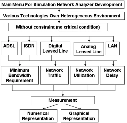
ABSTRACT
This paper presents a complete network analyzer development for network delay in campus environment. The purpose of this study is to define the accuracy of network analyzer development with independent data, real network and OPNET simulation tool. The network delay will measure based on transmission delay and propagation delay. This network analyzer software will test on delay generated by the several services. The reliability of this network analyzer will test with email, text messaging and instant messaging over web service. The results show that network analyzer software has accuracy and same trend delay with independent data, real network and OPNET simulation tool. Finally, this software is able to measure the network delay during preparation, proposal and planning phases.
Keywords: Accuracy, Traffic, Network Analyzer, OPNET
1. INTRODUCTION
This study focuses on the accuracy of network delay using heterogeneous services. This study does not intend to perform a comprehensive test the functionality of all simulator and analyzer features. OPNET has originally been developed for network simulation and it is fully usable as a robust and reliability simulation tool with higher investment. This network analyzer development process has discussed detail in [1], [2], [3]. Table 1.1 shows service performance requirement for several services. Service performance requirement consists of delay, capacity (bandwidth) and reliability [4]. Reliability is a measure of the network/system ability to provide deterministic and accurate delivery of information [5], [6]. Delay is a time difference in transmitting a single unit of information (bit, byte, cell, frame, and packet) from source to destination.
Table 1.1 Service Performance Requirements
2. DEFINITION OF NETWORK ANALYZER
A network analyzer also called a "packet analyzer," "traffic analyzer" and "protocol analyzer," [7]. Network analyzers functionality such as [8]: i) provide detailed statistics for current and recent activity on the network; ii) detect unusual levels of network traffic; iii) detect unusual packet characteristics; iv) identify packet sources or destinations; v) configure alarms for defined threats; vi) and vii) monitor bandwidth utilization.
Network Management: Network management consists of a variety of tasks, for example, monitoring, configuration, troubleshooting and planning that are performed by users and network administrators [9]. Network element is a component of the network that can be managed. This includes hosts, routers, switches, hubs and server that can be measured. Examples of end-to-end characteristics for network elements and network traffic are capacity (bandwidth), availability, delay, jitter, throughput, network utilization and error rates [10], [11].
3. METHODOLOGY
10 of six phases such as prepare, plan, design, implement, operate and optimize. This network analyzer development concentrates more on preparation, planning and proposal areas.
Figure 3.1: Comparison of Network Analyzer, OPNET and Real Network
Network analyzer development is based on mathematical model. We use queuing theory M/M/1 to build this software [13], [14]. This software was developed to measure and plan network activities such as predict usage of network delay. (refer to Figure 3.2). The reliability test will only concentrate on network delay.
Figure 3.2: Network Analyzer Modules Development
Figure 3.3 shows network delay reliability test. The independent data output is generated based on number of distance input, number of nodes input, size of bandwidth input and size of services input. These inputs will use in OPNET, real network and network analyzer software (refer to Figure 3.4).
Figure 3.3: Network Analyzer Accuracy Testing Process
Figure 3.4: Input Parameters for Network Analyzer, OPNET and Real Network
4. ANALYSIS AND RESULTS
11 real network design. Table 4.1 shows input for independent data for single user that will be used in network analyzer software, OPNET application and real network [15].
Figure 4.1: Network Design for Reliability Test
Table 4.1:Inputs for Independent Data to Evaluate Network Delay
Types of Services Size of Services Estimation E-mail (Low) 1000 Bytes Instant Messaging (Low) 500 Bytes
Text Messaging (Low) 100 Bytes
4.1 Independent Data – Network Delay
In our network delay experiment, independent data is used to measure network delay (transmission and propagation delay) reliability between network analyzer development, OPNET application and real network. Project conducted by David Grangier, Institut Eurecom, France, is selected to use as independent data [16] (refer to Figure 4.1 and Table 4.2).
Figure 4.1: Sample of Independent Data Input
Table 4.2: Independent Data Input Input to Measure Network Delay Network
Delay (Propagation
and Transmission
Delay)
Length (KM)
Rate (Mbps)
Packet size (Bytes) 10 0.512 100 100 1 and
10 500 1000 100 1000
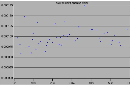
The following diagram output shows network delay over different packet size for single user (refer to Figure 4.2, Figure 4.3 and Figure 4.4).
Figure 4.2: Network Delay for 100 Bytes
Figure 4.3: Network Delay for 500 Bytes
Figure 4.4: Network Delay for 1000 Bytes
4.2 OPNET Application – Network Delay
12 Figure 4.3: OPNET Application: Network Delay
Design
Figure 4.4: Size of Text Messaging Configuration over Web Service
Figure 4.5: Size of Instant Messaging Configuration over Web Service
Figure 4.6: Size of Email Configuration over Web Service
The results show that OPNET application generates as follow network delay: i) 100 bytes – 0.000025sec/ 0.025ms to 0.0001sec/0.1ms; ii) 500 bytes – 0.00005sec/0.05ms to 0.00015sec/0.15ms; and iii) 1000 bytes – 0.000075sec/0.075ms to 0.00017sec/0.17ms (refer to Figure 4.7, Figure 4.8 and Figure 4.9).
Figure 4.7: Network Delay for Text Messaging
Figure 4.8: Network Delay for Instant Messaging (500 bytes)
13 4.3 Network Analyzer Development –
Network Delay
Then, network analyzer development will configure using the same input from independent data and OPNET application. First experiment will configure 5 km and second experiments will configure 10 km. The network analyzer development shows network delay results for 5 km (refer to Figure 4.10) and 10 km (refer to Figure 4.11).
Figure 4.10: Network Delay for 5 KM
4.4 Real Network – Network Delay
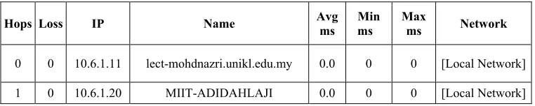
Real network environment has configured to enable network delay over LAN. The e-mail, text messaging and instant messaging traffic will pump using fluke network analyzer to the server. Network management tool such as ColaSoft Capsa and Visualware application are used to capture network delay. Figure 4.12 shows real network traffic for 100 bytes use by text messaging service that has received by the client. Table 4.3, Table 4.4 and Table 4.5 show network delay results generate by Visualware as follow: i) 100 bytes – 0ms; ii) 500 bytes – 0 ms to 1 ms; and iii) 1000 bytes – 0 ms to 2 ms.
Figure 4.14: Real Network – Network Delay for 100 Bytes (Text Messaging)
Figure 4.11: Network Delay for 10 KM
14
Hops Loss IP Name Avg ms Min ms Max ms Network
0 0 10.6.1.11 lect-mohdnazri.unikl.edu.my 0.0 0 0 [Local Network]
1 0 10.6.1.20 MIIT-ADIDAHLAJI 0.0 0 0 [Local Network]
Table 4.4: Network Delay – Instant Messaging (500 Bytes)
Hops Loss IP Name Avg ms Min ms Max ms Network
0 0 10.6.1.11 lect-mohdnazri.unikl.edu.my 0.0 0 0 [Local Network]
1 0 10.6.1.252 - 1.0 1 1 [Local Network]
2 0 10.51.1.254 - 0.0 0 0 [Local Network]
Table 4.5: Network Delay – E-mail (1000 Bytes)
Hops Loss IP Name Avg ms Min ms Max ms Network
0 0 10.6.1.11 lect-mohdnazri.unikl.edu.my 0.0 0 0 [Local Network]
1 0 10.6.1.252 - 1.66 1 2 [Local Network]
2 0 10.51.1.254 - 0.0 0 0 [Local Network]
We conclude all our findings in Table 4.6 and Table 4.7. The results generate from network analyzer is closely resemble with OPNET application, real network and independent data. Again, it is confirm and proof that network analyzer development is able to predict and plan network delay usage for heterogeneous services.
Table 4.6: Network Delay - Reliability of Network Analyzer Development between Opnet,
Independent Data and Real Network
Table 4.7: Network Delay - Reliability of Network Analyzer Development between Opnet,
Independent Data and Real Network
5. CONCLUSION
15 approximately same as OPNET simulation tool, independent data and real network for network delay. This network analyzer development can use to measure and analyze network delay behavior for preparation and planning purposes. In addition, it is easy to use and provide a user-friendly graphical and text interface.
REFRENCES:
[1] M. Fleury, G. Flores Lucio, and M. J. Reed. “Clarification of the ‘OPNET NS-2 Comparison’ Paper with. regards to OPNET Modeler”.
http://privatewww.essex.ac.uk/~fleum/OPN
ET-NS2_Comparison.pdf, accessed
9/9/2008.
[2] Brown K, Christianson L, OPNET Lab Manual to Accompany Data and Computer Communications 7th ed. And Computer Networking with Internet Protocols and Technology 4th ed. by William Stallings, Pearson Prentice Hall, Upper Saddle River, NJ, 2005.
[3] Xinjie Chang. 1999. “Network Simulations With OPNET”. Proceedings of the 1999 Winter Simulation Conference P. A. Farrington, H. B. Nembhard, D. T. Sturrock, and G. W. Evans, eds.
[4] James D. McCabe. “Practical Computer Network Analysis and Design”, pp. 15 – 40, 1998, Morgan Kaufmann Publishers. [5] Michael R. Lyu. “Software Reliability
Engineering: A Roadmap”, International Conference on Software Engineering, pp.
153-170, 2007.
[6] Abdullah Konak. “Combining network reductions and simulation to estimate network reliability”, Proceedings of the
39th conference on Winter simulation, pp. 2301-2305, 2007. [Oktober 11, 2009] [7] Victor A. Clincy & Nael Abu-Halaweh.
2005. “A Taxonomy of free Network Sniffers for teaching and research”, Source” Journal of Computing Sciences in Colleges Vol. 21(1), pp. 64 – 75.
[8] J. P. Talledo. 2005. “Design and Implementation of an Ethernet Frame Analyzer for High Speed Networks”, Proceedings of the 15th International Conference on Electronics, Communications and Computers, Publisher IEEE Computer Society pp. 171 – 176.
[9] Jairo A. Gutiérrez. “A connectionless approach to integrated network management”,
International Journal of Network Management Vol. 8(4), pp. 219 – 226, 1998, John
Wiley & Sons, Inc. New York, NY, USA [10] Faouzi Kamoun. “Toward best
maintenance practices in communications network
management”, International Journal of Network Management,Vol. 15(5), pp. 321 – 334, 2005, John Wiley & Sons, Inc. New York, NY, USA
[11] A.S. Sethi. “Bibliography on network management”, ACM SIGCOMM Computer Communication Review, Vol. 19(3), pp.
58-75, 1989.
[12] Cisco Networks. 2007. “Cisco’s Life Cycle Services Approach”, Cisco Networkers Conference 07, Januari 2007, Sunway Pyramid, Malaysia.
[13] Mohd Nazri Ismail, Abdullah Mohd Zin, "Comparing the Accuracy of End-to-End Network Performance Measurement Testbed and Simulation Model for Data Transfers in Heterogeneous Environment," ams, pp. 124-131, IEEE, Second Asia International Conference on Modelling & Simulation (AMS), 2008.
[14] Mohd Nazri Ismail and Abdullah Mohd Zin. “Development of Simulation Model in Heterogeneous Network Environment: Comparing the Accuracy of Simulation Model for Data Transfers Measurement over Wide Area Network”. Asian Network for Scientific Information. Information Technology Journal, pp. 2448, 2008. ISSN: 1812-5638 (Print). Pakistan.
[15] Hans Lohninger. “Wireless Networking in the Developing World”, January 2007,
[Online access],
http://www.vias.org/wirelessnetw/
wndw_05_07.html