Poland
8
* Correspondence: [email protected]; Tel.: +48-697-322-2
9
10
Abstract: Carrying out technological tests and research is indispensably connected with high costs
11
and elongation of implementation time of new casting technologies and their modifications in
12
industry. Hence, the application of specialised computer software, enabling the simulation and
13
analysis of metallurgical and casting processes in modern foundry industry is of special interest.
14
The present work presents an experimental application of MAGMASoft software in casting process
15
of EV31A magnesium alloy structural element of helicopter engine. The results of computer
16
simulation have been compared with industrial cast of the simulated element, fabricated in the
17
same conditions. It has been revealed that the computer simulation provides a complex
18
information on the analysed process, leading to reduction of costs and time, connected with
19
technological tests in implementation of new casting technologies.
20
Keywords: magnesium alloy, EV31A, MAGMASoft, simulation, casting, foundry.
21
22
1. Introduction
23
Development of structural elements for aerospace and automotive industry is focused on the
24
decrease of weight and simultaneous increase of mechanical properties at both ambient and elevated
25
temperature [1-2]. Hence, in the design process of modern aircraft engines the new generation
26
of magnesium alloys is of special interest. This group of modern lightweight alloys is characterised
27
by the low density, enabling the enhancement of flight dynamics, as well as good high temperature
28
mechanical properties [3].
29
Analysis of research reports and literature confirms the intense cooperation of modern industry
30
with research centers, leading to replacement of recently used cast alloys by newly developed alloys
31
exhibiting better application parameters. One of the widely employed group of cast magnesium
32
alloys are Mg-Al alloys, with addition of other alloying elements. Although they show excellent
33
casting properties, good tightness, machinability and mechanical properties, as well as relatively
34
good corrosion and hot cracking resistance, these properties are limited to 120˚C [4]. The significant
35
deterioration of properties of Mg-Al alloys in temperature exceeding 120˚C has been attributed to
36
the presence of α-Mg+Mg17Al12eutectic compound, with low melting point of 437˚C and precipitates
37
of brittle Mg17Al12 intermetallic phase located on grain boundaries of α-Mg solid solution [5].
38
To overcome the problem of intergrain cracking of castings (described cracking phenomena has
39
been observed in turbine engines, operating in extreme conditions in the vicinity of fairings and
40
anti-icing valve mount, where the temperature is around 151˚C and 175˚C) it is necessary to replace
41
Mg-Al alloy with modern Mg-RE sand-casting alloy, characterised by working temperature up to
42
200÷300˚C, what is associated with essential changes in fabrication of casting molds and liquid alloy
43
preparation [2, 6-7]. Among the commercial magnesium alloys, the best high temperature properties
44
are presented by WE43 and WE54 alloys and are achieved by the addition of expensive rare earth
45
elements (mainly neodymium) and yttrium [8-9]. A good alternative for these alloys is the modern
46
EV31A alloy, containing gadolinium instead of yttrium. Its properties are slightly lower, but still
47
meet the requirements for many applications in the automotive and aerospace industry [10].
48
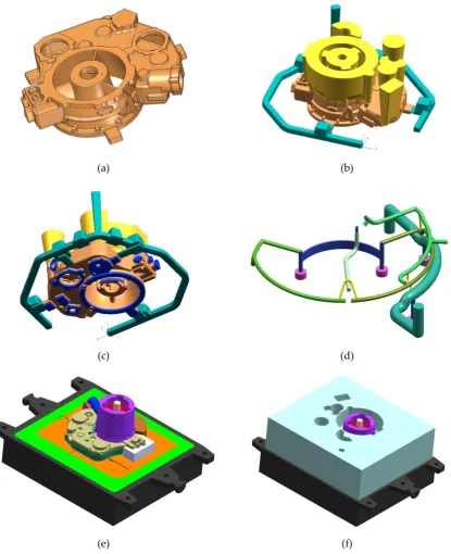
Different physicochemical properties of newly used alloy, such as fluidity and solidification rate
49
cause also the substantial changes in mold pouring process and casting solidification. The design
50
process of new casting technology requires its verification, what may be achieved by conducting
51
expensive technological tests. However, the costs and implementation time could be reduced by
52
application of specialised software, enabling the detailed simulation and analysis of casting process,
53
such as MAGMASoft [11-13].
54
In the present work the analysis of casting process of new EV31A magnesium alloy helicopter
55
turbine engine element based on computer simulation using MAGMASoft software has been carried
56
out. The novel character of presented research is motivated by the fact, that EVA31A is relatively
57
new alloy, therefore the information on its casting process simulation, as well as alloy databases are
58
strongly limited. Results of computer simulation have been compared with identical casting,
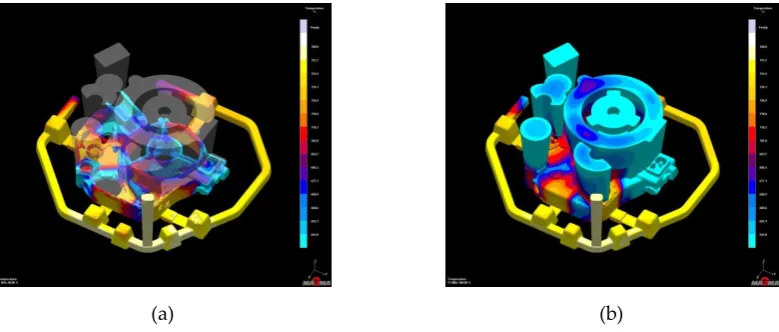
59
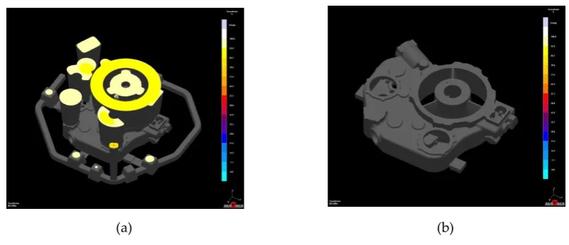
obtained in technological test, confirming an important role of computer simulation in design
60
process of new casting technologies.
61
2. Materials and Methods
62
The research material was sand cast EV31A magnesium alloy with the composition given in
63
Table 1. The MAGMASoft software database does not include sufficient data on EV31A alloy for the
64
correct simulation of casting process. As this alloy is increasingly applied in industrial practice, it is
65
important to support the sufficient data, including thermo-physical and physiochemical properties.
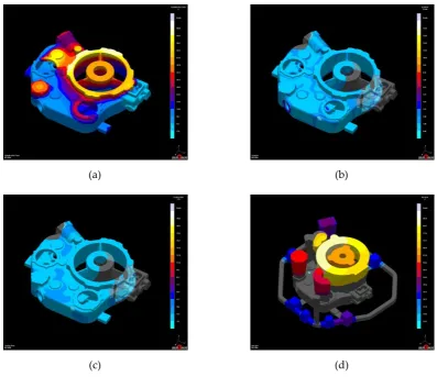
66
A set of simulation input parameters, including density, specific heat and thermal conductivity in
67
the funticon of temperature, as well as liquidus and solidus temperatures has been measured and
68
presented in the previous work by Jarosz, Kiełbus and Dybowski [14].
69
Table 1. Chemical composition of EV31A magnesium alloy (wt. %)
70
Gd Nd Zr
Zn
Mn
Fe
Ag
TRE
Mg
1.2 2.7 0.49 0.4 0.001 0.003 0.01 4.2 Balance
The commercial engine inlet body have been sand casted using commercial EV31A alloy under
71
the inert atmosphere of Ar (6 dm3/min), CO2 (6 dm3/min) and SF6 (0.16 dm3/min). Casting
72
temperature has been set to 760÷780˚C with previous homogenization of the melt by stirring (30÷120
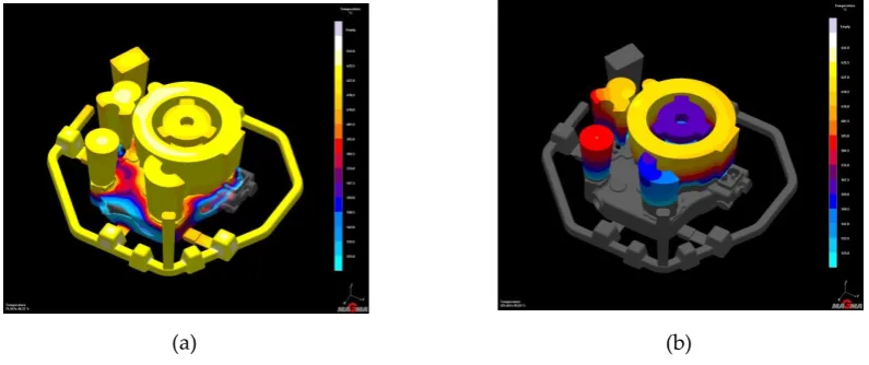
73
rpm, 20 min.). The visual examination of the casting has been carried out and X-Ray images (AGFA
74
apparatus) have been acquired.
75
In order to verify the potential of computer simulation in new casting technology
76
implementation, the simulation of mold pouring and solidification of engine inlet body casting has
77
been conducted. In the simulation two modules of MAGMASoft software have been used:
78
MAGMAfill and MAGMAsolid. A new MAGMA5 computing option (SOLVER 5) has been applied,
79
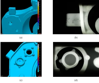
due to the better simulation of actual casting process conditions. The 3D model of investigated
80
element have been prepared using Unigraphics NX2 software. The developed 3D model is an image
81
of the actual dimensions of the casting, as well as construction of the casting mold (Figure 1).
82
83
84
85
(a) (b)
(c) (d)
(e) (f)
Figure 1. 3D model of investigated engine inlet body casting: (a) 3D solid of casting; (b) 3D solids
87
of casting, gating system and runners; (c) 3D solids of casting, gating and cooling systems;
88
(d) 3D solid of Cr-Ni tube collector embedded in the casting; (e) 3D solids of base plate, 21 assembled
89
mold cores and Cr-Ni tube collector; (f) 3D solids of assembled mold with cores in casting-ready
90
state.
91
Because of the complex shape of the casting, the 3D model mesh has been densified locally
92
to eliminate computing mistakes (the MRS mesh generated by MAGMASoft may be the source
93
of mentioned mistakes due to its stair stepped shape).
94
95
3. Results and discussion
97
3.1. Simulation and analysis of mold filling process
98
Simulated mold filling process shows the stages of liquid alloy flow through the individual
99
elements of mold interior. The construction of filling system, comprising four filling gates allows
100
a uniform temperature gradient and minimalises a probability of high volume overheatings
101
(Figure 2).
102
(a) (b)
Figure 2. 3D image of temperature gradient: (a) 30% of mold filling; (b) 100% of mold filling.
103
Application of multiple filling gates reduces the temeperature differences, what has a beneficial
104
influence on risers charging during the solidification process. On the other hand the risk of liquid
105
metal fluxes collision appears, causing the turbulences and filling disorders. Hence, the significant
106
turbulences, occuring during the fulxes collisions may result in the formation of casting defects, such
107
as cold shuts, misruns, gas porosity and secondary oxidation of liquid magnesium alloy (Figure 3d).
108
Velocity criterion shows the exceeding of critical value of flow speed (0.5 m/s), what may lead to
109
division of the main liquid alloy flux and increase of oxidation risk (Figure 3c). In the same time the
110
AirEntrapment parameter determines the percent content of air entraped in the flowing liquid metal.
111
In the moment of fluxes collision and exceeding of critical flow speed the amount of air entraped in
112
liquid alloy reaches over 20% (Figure 3b). Moreover the occurring turbulences might cause the metal
113
penetration and erosion of mold material, leading to entrapment of small inclusions of molding
114
material in the structure of casting.
115
(c) (d)
Figure 3. Effects of turbulences, occuring during the mold filling process (10% of mold filling): (a) Temerature
116
gradient; (b) Air entrapment; (c) Flow speed; (d) Porosity and casting defects of real casting in areas, indicated
117
in MAGMASoft simulation.
118
MAGMASoft simulation has confirmed the risk of formation of oxide inclusions with a high
119
accuracy in comparison with the real casting. The mentioned defects suorce from the turbulent flow
120
of liquid alloy, caused by the complicated design of the mold and shape obstacles, like protrusions,
121
recesses and winding channels (Figure 4). Additionaly the complexicity of mold filling process,
122
affected by many different factors, that may determine the mutual deceleration of the liquid melt
123
fluxes alters the mold pouring time.
124
(a) (b)
Figure 4. Effects of turbulent flow of the melt on final casting: (a) Trajectories of melt fluxes;
125
(b) Oxides, insclusions and porosity in the vicinity of gate.
126
The final result of mold filling simulation is presented in Figure 5 and has been determined
127
according to criterions of maximum fluxes length (maximum value of 1900 mm) and overall filling
128
time (17 s).
(a) (b)
Figure 5. Final result of mold filling simulation: (a) Maximum fluxes length; (b) Overall filling time.
130
3.2. Simulation and analysis of casting solidification process
131
EV31A magnesium alloy is characterised by relatively high volume shrinkage. Hence, the
132
effective charging of casting thermal centers with liquid alloy is needed. Elements controlling the
133
solidification process, such as risers, ensure the constant charging of thermal centers with liquid
134
alloy and compensating the volume shrinkage. In the same time the application iron coolers
135
accelerates the heat dissipation from overheated parts of the casting and causes the transfer of the
136
volume shrinkage to the vicinity of risers (Figure 6).
137
(a) (b)
Figure 6. Simualtion of temperature gradient during the solidification of the casting: (a) 40% of solidification;
138
(b) 95% of solidification.
139
Despite the application of highly developed cooling and charging systems, as well as efforts on
140
preventing the microporosity formation, the disortions of solidification process in industrial
141
conditions are possible. The complex shape of the casting, overheatings and insufficient charging
142
of heat centers with liquid alloy favors the apperance of local crystalisation fronts are the reason
143
of casting shrinkage deffects formation. The mentioned defects tend to from in the vicinity of gates
144
and runners, where the solidification time is relatively long in comparison with other parts of the
145
casting, despite of presence of coolig elements (Figure 7).
(a) (b)
Figure 7. Simulation of microporosity formation: (a) upper part of the casting; (b) lower part of the casting.
147
The results of MAGMASoft simulation have been confirmed by the technological test and
148
X-Ray examination of the real cast. Groups of oxide and nonmetallic inclusion appears together with
149
microporosity in the vicinity of gates, runners and risers (Figure 8).
150
(a) (b)
(c) (d)
Figure 8. Analysis of shrinkage deffects: (a) Microporosity in the vicinity of gate (simulation);
151
(b) Correspongind X-Ray image of the vicinity of gate (real casting); (c) Microporosity in the vicinity of riser
152
(simulation); (d) Correspongind X-Ray image of the vicinity of riser (real casting).
153
High temperature of the melt, local overheatings and lengthening of solidifcation time causes
155
the burns of molding material and its adhesion to the casting surface (Figure 9), resulting in the
156
increase of the surface roughness, which needs the further machining, rising the element’s
157
production costs and time.
158
(a) (b)
Figure 9. Molding material burns and adhesion: (a) MAGMASoft simulation; (b) Real casting.
159
The simulation of engine inlet body solidification process required the consideration of some
160
additional criteria, due to the fact, that the occurring deffects are not directly determined by the
161
standard quality criteria (Soundness and Porosity). Specific properties of EV31A alloy, especially the
162
problem of different contaminations presence are factors difficult to determine in the mathematical
163
model of simulation software. The results of Soundness criterion, determining the internal quality of
164
the casting indicates only the defects in the sprue and charging system. However, the casting itself is
165
free of shrinkage and porosity (Figure 10).
166
(a) (b)
Figure 10. Visualisation of Soundness criterion (X-Ray): (a) Casting with charging system; (b) Casting.
167
The described inaccuracies have determined the necessity of analysis of other criteria, such as
168
mold overheating rate, cooling rate, solidification time, etc. (Figure 11). The synthesis of these results
169
enabled the estimation and analysis of critical casting parts in terms of probability of shrinkage
170
defects formation (microporosity, shrinkage cavities, etc.).
(a) (b)
(c) (d)
Figure 11. Analysis of shrinkage deffects formation probability: (a) Solidification rate simulation;
172
(b) Gradient of heat dissipation per surface unit; (c) Heat dissipation rate simulation; (d) Hot Spots simulation
173
(the latest solidifying parts of casting).
174
4. Summary
175
The results of computer simulation of engine inlet body casting process enabled the
176
identification of potential problems and factors, causing the decrease of final casting quality. The
177
obtained results have been confirmed with high accuracy in the technological tests, comprising
178
casting of investigated element and its analysis in industrial conditions. Excessively high flow speed
179
of liquid alloy, revealed in the conducted research determine the application of solutions, leading to
180
the decrease of flux speed and reduction of flow turbulences (Figure 12).
181
182
(a) (b)
Figure 12. Applied solutions of problems identified during the conducted research: (a) 10ppi ceramic filters;
183
10ppi ceramic filters have been introduced in deslagging basins and the height of gates has been
185
increased from 7 mm to 12 mm. Additionally, applied ceramic filters will protect the casting
186
contamination with nonmetallic inclusions and primary oxide inclusions, formed during the melting
187
process.
188
It has been revealed, that the computer simulation is an interesting tool in implementation
189
of new casting technologies in foundry industry. Its application may result in significant cost and
190
time reduction, due to the possibility of replacing some technological tests with computer
191
simulation.
192
Acknowledgments: The financial support for the present research was provided as a joint venture of Institute
193
of Materials Engineering, Silesian University of Technology and ZM "WSK Rzeszów" Sp. z o. o. under the
194
research agreement No. BK-221/RM3/RM0/2018 (11/990/BK_18/0057).
195
Author Contributions: R. Jarosz and A. Kiełbus conceived, designed and performed the experiments;
196
R. Jarosz, A. Kiełbus and A. Gryc analysed the data; A. Gryc summarise the results and wrote the article.
197
6. Research Project No. 04590/C.ZR7-6/2010.
210
7. Rzychoń T., Szala J., Kiełbus A., Microstructure, Castability, Microstructural Stability and Mechanical
211
Properties of ZRE1 Magnesium Alloy, Arch Metall Mater 2012, 57, pp. 245-252,
212
DOI: 10.2478/v10172-012-0018-3.
213
8. Trojanová Z., Száraz Z., Chmelík F., Luká P., Acoustic emission from deformed Mg-Y-Nd alloy and this
214
alloy reinforced with SiC particles, J Alloy Compd2010, 504, pp. 9-12, DOI: 10.1016/j.jallcom.2010.05.138.
215
9. Wang J. G., Hsiung L. M., Nieh T. G., Mabuchi M., Creep of a Heat Treated Mg-4Y-3RE Alloy, Mat Sci Eng
216
A2001, 315, pp. 81-88.
217
10. Bronfin B., Moscovitch N., New Magnesium Alloys for Transmission Parts, Met Sci Heat Treat2006, 48, pp.
218
479-486, DOI: 10.1007/s11041-006-0121-z.
219
11. Böttger B., Eiken J., Steinbach I., Phase Field Simulation of Equiaxed Solidification in Technical Alloys,
220
Acta Mater2006, 54, pp. 2697-2704, DOI: 10.1016/j.actamat.2006.02.008.
221
12. Sun Z., Hu H., Chen X., Numerical Optimization of Gating System Parameters for a Magnesium Alloy
222
Casting With Multiple Performance Characteristics, J Mater Process Technol 2008, 199, pp. 256-264,
223
DOI: 10.1016/j.jmatprotec.2007.08.036.
224
13. Yan H., Zhuang W., Hu Y., Zhang Q., Jin H., Numerical Simulation of AZ91D Alloy Automobile Plug in
225
Pressure Die Casting Process, J Mater Process Technol 2007, 187-188, pp. 349-353,
226
DOI: 10.1016/j.jmatprotec.2006.11.186.
227
14. Jarosz R., Kiełbus A., Dybowski B., MAGMASoft Simulation of Sand Casting Process With EV31A
228