Article
1
Improved Current Doubler Rectifier
2
Mihail Antchev 1*
3
1 Section Power Electronics, Faculty of Electronic Engineering and Technology, Technical university - Sofia,
4
Sofia 1000, Bulgaria; [email protected]
5
* Correspondence: [email protected]; Tel.: +359-2-965-3321
6
7
Abstract: It is widespread to examine and explain the functioning of the standard “Current
8
Doubler Rectifier” as strictly symmetrical according to the electrical current through the two
9
inductances. The present work challenges this consideration and proposes a new version of the
10
electrical circuit daigram where the current symmetry is improved. The proposed circuit is called
11
“Improved Current Doubler Rectifier”.
12
Keywords: rectifier; current doubler; symmetry
13
14
1. Introduction
15
The advantages of the "Current Doubler Rectifier" compared to the "Voltage Doubler Rectifier"
16
for DC-to-DC converters are known [1]. There is also an option with transistors in the secondary side,
17
called "Synchronous current doubler rectifier" [2,3,4,5,6]. Other options use "coupled inductors"
18
[7,8,9]. Normally, the functioning of the "Current Doubler Rectifier", here called standard "Current
19
Doubler Rectifier", is examined in an established mode of operation [10,11,12]. In this mode, if there
20
is a voltage on the secondary coil of the transformer, the difference between this and the output
21
voltage is applied to one of the inductances and the current through it increases. At the same time
22
interval, on the other inductance is applied the output voltage, and the current through it decreases.
23
At zero voltage on the secondary coil of the transformer the currents through the two inductances
24
decrease. In this standard examining, the currents through both inductances have the same directions
25
at all time intervals, as they only increase or decrease. This consideration neglects the start-up process,
26
in which it turns out that the current through one of the two inductances has the opposite direction
27
to that of the established mode.
28
*
*
1
L
L
2
+
−
1
VD
2
VD
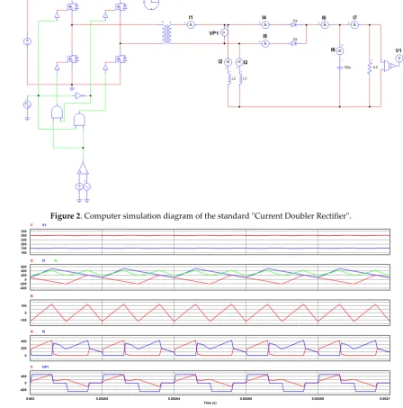
C
R
L*
*
1
L I
2
L
I
L
CR
I
29
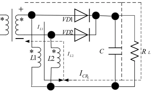
Figure 1. Diagram for clarifying the operation in the first cycle
30
31
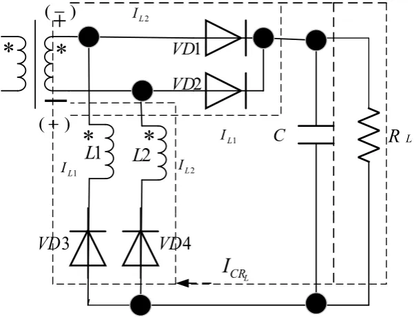
Figure 1 shows the principle diagram and the voltage and current indications during the first
32
operation cycle of the standard "Current Doubler Rectifier" after the converter has been started. It is
33
assumed that the voltage of the secondary coil of the transformer has the polarity shown in the figure.
34
It is seen that the current I flows through the inductance L from the bottom to the top of the
35
circuit as it increases now and at any subsequent interval during which the polarity of the secondary
36
coil voltage is the same. During the pause and change of polarity, this current decreases but keeps its
37
direction. In this first cycle, the current 𝐼 flows as well, but in the opposite direction through the
38
inductance L - from top to bottom of the circuit. This violates the symmetrical operation of the
39
standard "Current Doubler Rectifier". It is only when changing the polarity of the voltage of the
40
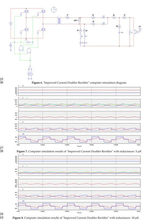
secondary coil in the next cycle, when the current 𝐼 will change its direction. An additional source
41
of asymmetry is the increase in the voltage of capacitor 𝐶 after each operation cycle during the
42
startup process. For example, in the first cycle, the current I is changing at the highest speed, as
43
the capacitor is discharged. In the next cycle, the current I , besides starting from a negative value,
44
will also change at a slower speed as the capacitor is charged to some voltage from the first cycle, and
45
so on.
46
The difference in the two currents in the first cycle leads to different starting conditions. In
47
subsequent cycles during the startup process, some additional asymmetry causes increase in
48
capacitor 𝐶 voltage after each cycle. As a result, during the time, at periodical operation the average
49
value of current 𝐼 remains lower than that of the current 𝐼 . As a result, the currents through
50
the two diodes VD1 and VD2 are different, as well as the current through the secondary coil of the
51
transformer has a direct current component. Similarly, if in the first operation cycle the polarity of
52
the voltage of the secondary coil is opposite to that shown in Figure 1, then the average current 𝐼
53
value will be lower than that of 𝐼 . A difference in the average values of the two currents is noted in
54
the results of the experimental studies published in other articles, for example [6] (fig.14), [10] (fig.4),
55
[13] (fig.14), [14] (p.32). This difference remains in the case of "coupled inductors" - [9] (fig.9a). The
56
equalization of currents through the two inductances is paid attention in [15], where a "modified
57
current doubler rectifier" is proposed and the equalization is on the average values of the currents.
58
This article introduces a simplified modification of the standard solution called "Improved
59
Current Doubler Rectifier", which avoids, to a large extent, the above-mentioned disadvantages.
60
Comparative results of computer simulation and experimental research are presented.
61
62
2. Computer simulation results
63
64
The above-mentioned conclusions about the difference in the average values of the currents
65
through the two inductances, due to the different operating conditions in the first cycle, are confirmed
66
in the present work with the help of computer simulation diagram done with PSIM program shown
67
in Figure 2. The observed values are indicated in the diagram and they are shown in Figure 3 and
68
Figure 4 for different inductance values. The indications of the values shown in the time diagrams
69
are seen in Fig. 2: I2, I3 – electric currents through the inductances; I1, VP1- electric current and
70
secondary coil voltage; I4, I5 – electric currents through the diodes; I6 - the sum of I2 and I3; I8 -
71
current through the capacitor; I1, V1 - current and voltage of the load.
72
Preprints (www.preprints.org) | NOT PEER-REVIEWED | Posted: 27 August 2018 doi:10.20944/preprints201808.0444.v1
73
Figure 2. Computer simulation diagram of the standard "Current Doubler Rectifier".
74
75
Figure 3. Computer simulation results of a standard "Current Doubler Rectifier" with inductances 5 𝜇𝐻.
76
77
Figure 4. Computer simulation results of standard "Current Doubler Rectifier" with inductances 10 𝜇𝐻
.
78
100 150 200 250 300 350
I7 V1
0 -200 -400 200 400 600
I2 I3 I6
0 -100 100 I8
0 200 400
I4 I5
0.002 0.00202 0.00204 0.00206 0.00208 0.0021 Time (s)
0 -400 400
I1 VP1
0 100 200 300 400 500
I7 V1
0 400 800
I2 I3 I6
0 -200 -400 200 400 600 I8
0 400 800
I4 I5
0.002 0.00202 0.00204 0.00206 0.00208 0.0021 Time (s)
0 -400 400
The comparison of the results of Figure 3 with those of Figure 4 shows that at a higher
79
inductances value the effect in question is less expressed, i.e. the difference in the values of the
80
average currents through them is smaller. Perhaps this is the reason why researchers did not notice
81
the difference in currents and did not pay attention to the start-up processes.
82
To avoid the asymmetry due to the first operating cycle, this article proposes the successive
83
connection of diodes to inductances, as the this circuit is called "Improved Current Doubler Rectifier"
84
– Figure 5. It shows that in the first operation cycle at the shown polarity of the voltage of the
85
secondary coil without brackets, electric current flows only through the inductance L in direction
86
from the bottom to the top of the diagram. Due to the presence of 𝑉𝐷3 in this first cycle, there is no
87
current flowing through the inductance 𝐿 . When changing the polarity of the voltage in the second
88
cycle, shown in the figure in brackets, current will flow through the inductance 𝐿 , in direction from
89
bottom to top. The diagram will have the same results if the first cycle corresponds to the polarity of
90
the voltage shown in brackets. In this way, the circuit becomes symmetrical with respect to the two
91
currents in their first cycle. From the diagram of Figure 5, it is seen that a single-phase bridge rectifier
92
is connected to the secondary coil of the transformer, as the inductances are being connected
93
successively with the diodes from the anode group𝑉𝐷3, 𝑉𝐷4. It should be noted that only the
94
asymmetry due to the gradual charging of the capacitor 𝐶 during the startup process remains.
95
96
*
*
1
L
L
2
+
−
1
VD
2
VD
C
R
L*
*
1
L
I IL2
L
CR
I
3
VD
VD
4
)
(
+
)
(
−
IL21
L I
97
Figure 5. Diagram for clarifying the functioning of "Improved Current Doubler Rectifier".
98
99
The operation of "Improved Current Doubler Rectifier" is checked with the computer simulation
100
diagram shown in Figure 6. The results are presented in Figure 7 and Figure 8 for the same values of
101
the two inductances corresponding to Figure 3 and Figure 4. Figure 7 and Figure 8 show almost
102
complete symmetry of the circuit in terms of currents through inductances, currents through the
103
diodes, and lack of a direct current component through the secondary coil of the transformer.
104
Preprints (www.preprints.org) | NOT PEER-REVIEWED | Posted: 27 August 2018 doi:10.20944/preprints201808.0444.v1
105
Figure 6. "Improved Current Doubler Rectifier" computer simulation diagram.
106
107
Figure 7. Computer simulation results of "Improved Current Doubler Rectifier" with inductances 5 𝜇𝐻.
108
109
Figure 8. Computer simulation results of "Improved Current Doubler Rectifier" with inductances 10 𝜇𝐻
.
110
111
0 100 200 300 400 500
I7 V1
0 400 800 1200
I2 I3 I6
0 -400 400 800 I8
0 400 800 1200
I4 I5
0.002 0.00202 0.00204 0.00206 0.00208 0.0021 Time (s)
0 -400 400
I1 VP1
0 100 200 300 400 500
I7 V1
0 400 800
I2 I3 I6
0 -200 -400 200 400 600 I8
0 400 800
I4 I5
0.002 0.00202 0.00204 0.00206 0.00208 0.0021 Time (s)
0 -400 400
3. Experimental investigation
112
113
To investigate the start-up processes, a bridge DC / DC converter with a high-frequency
114
transformer has been implemented. This converter is powered by a voltage with a value 300𝑉,
115
obtained after rectification the voltage of the power supply network. In the converter control
116
system, special measures are provided to ensure the symmetrical operation of the diagonally
117
connected transistors in both half periods. In the first part of the experiment, a standard "Current
118
Doubler Rectifier" of Figure 1 is connected in the secondary side at inductances value of 21𝜇𝐻. The
119
values of the two inductances are specifically selected to be equal, and the measurement is done with
120
an electronic RLC meter. Figure 9 and Figue 10 show oscillograms from the initial run experiment at
121
different time scales. When monitoring the oscillogram of the voltage on the secondary coil of the
122
transformer, the active end of the voltage probe on the oscilloscope's first channel is connected to the
123
anode of 𝑉𝐷2 diode, and the ground - to the anode of diode 𝑉𝐷1. The currents are monitored by a
124
current probe, connected to the second channel at a 100mV / A scale. The probe is connected so, that
125
the positive direction of the current through it is from the end to the beginning of each inductance.
126
On all the oscillograms shown below, the voltage scale of CH1 is 10V / div, and the current scale of
127
CH2 is 10A / div.
128
129
130
131
132
133
134
135
136
137
138
139
140
141
a b
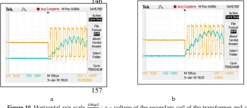
142
Figure 9. Horizontal axis scale : а – voltage of the secondary coil of the transformer and current
143
through inductance 𝐿 , b - voltage of the secondary coil of the transformer and current through inductance𝐿 .
144
145
146
147
148
149
150
151
152
153
154
155
156
157
a b
158
Figure 10. Horizontal axis scale : а – voltage of the secondary coil of the transformer and current
159
through inductance 𝐿 , b - voltage of the secondary coil of the transformer and current through inductance 𝐿 .
160
161
From the comparison of Figure 9a and Figure 9b can be seen the difference in the first operation cycle. At
162
the described connection of the first channel voltage probe, the first cycle corresponds to the negative voltage of
163
Preprints (www.preprints.org) | NOT PEER-REVIEWED | Posted: 27 August 2018 doi:10.20944/preprints201808.0444.v1
the anode 𝑉𝐷2 to the anode of 𝑉𝐷1 (therefore positive voltage of anode of 𝑉𝐷1 to the anode of 𝑉𝐷2). At this
164
first cycle the current through 𝐿 flows in the opposite direction and in the second cycle starts from a negative
165
value that is -2A. In the first cycle the current through 𝐿 starts from zero value.
166
From the comparison of Figure 10a and Figure. 10b can be seen the difference in the maximum values of
167
currents during the start-up process - for the inductance 𝐿 the maximum value is 28A and for the inductance
168
𝐿 - 33A. Therefore, the difference in the maximum values is 5A.
169
In the second part of the experiment, in the secondary side is connected the so-called "Improved Current
170
Doubler Rectifier" only by adding the two diodes 𝑉𝐷3, 𝑉𝐷4 of the anode group in Figure 5, at the same
171
inductances value 21𝜇𝐻 Figure 11 and Figure 12 show oscillograms from the start-up processes in different
172
time scales. The position and scale of the voltage and current probes is unchanged.
173
174
175
176
177
178
179
180
181
182
183
184
185
186
a b
187
Figure 11. Scale on horizontal axis : а - voltage of the secondary coil of the transformer and current
188
through inductance 𝐿 , b - voltage of the secondary coil of the transformer and current through inductance 𝐿 .
189
190
191
192
193
194
195
196
197
198
199
200
201
202
203
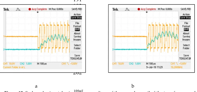
a b
204
Figure 12. Scale on horizontal axis : а - voltage of the secondary coil of the transformer and current
205
through inductance 𝐿 , b - voltage of the secondary coil of the transformer and current through inductance 𝐿 .
206
207
From the comparison of Figure 11a and Figure 11b it is seen that there is no current flowing through the
208
inductance 𝐿 in the opposite direction during the first cycle (unlike Figure 9a). During the second cycle this
209
current starts at zero value. In the first cycle, the current through 𝐿 starts from a zero value as it is in Figure
210
9b.
211
F
rom the comparison of Figure 12a and Figure 12b the difference in the maximum current values during212
the start-up process is visible - for the inductance 𝐿 the maximum value is 24A and for the inductance 𝐿 28A.
213
Therefore, the difference in the maximum values is 4A and it is reduced compared to the first case. Although
214
described in the introduction.
216
217
4. Conclusions
218
The results of the researches through computer simulation and these of the experimental studies confirm
219
the original theoretical examination and prove the advantages of the offered in the present work "Improved
220
Current Doubler Rectifier", namely: improving the symmetry of the currents through the two inductances (at
221
their fully equal values and symmetric control of the converter in the primary side); lack of a direct current
222
component in the secondary coil of the transformer. These advantages are achieved by a simple modification of
223
the standard circuit. The advantage, however, is at the expense of a certain disadvantage - the increased number
224
of "Improved Current Doubler Rectifier" diodes. The proposed circuit could be developed and tested though
225
synchronous current rectification in the secondary side, similar to the "Synchronous current doubler rectifier".
226
227
Conflicts of Interest: The author declare no conflict of interest.
228
References
229
1. Balogh L., The Current-Doubler Rectifier: An Alternative Rectification Technique for Push-Pull and Bridge
230
Converters, Design Note 63, Unitrode Applications Handbook, 1997, pp.4-79-4-81.
231
2. Mappus S., PWM IC’s AB Outputs Drive Synchronous Rectifier, Power Electronics Technology, 2003,
232
February, pp.52-56.
233
3. Texas Instruments, Control Driven Synchronous Rectifiers in Phase Shifted Full Bridge Converters,
234
Application Note SLUA287, 2003, March.
235
4. Chiang P., M. Hu, Switching Analysis of Synchronous Rectifier MOSFET’s with Phase Shifted Full-Bridge
236
Converter and Current Doubler, Vishay Siliconix, Application Note 833, 2007, October.
237
5. Texas Instruments, Using the UCC3895 in a Direct Control Driven Synchronous Rectifier Applications,
238
User’s Guide SLUU109B, 2009, February.
239
6. Garsia R., ISL6752/54EVAL1Z ZVS DC/DC Power Supply with Synchronous Rectifier User Guide, Intersil
240
AN1603, 2011.
241
7. Wu Tsai-Fu, C. Tsai, Y. Chang, Y. Chen, Analysis and Implementation of an Improved Current-Doubler
242
Rectifier with Coupled Inductors, IEEE Transactions On Power Electronics, 2008, Vol.23, No6, November,
243
pp.2681-2693.
244
8. Huber L., M. Jovanovic, Forward- Flyback Converter with Current-Doubler Rectifier with Coupled
245
Inductors: Analysis, Design, and Evaluation Results, IEEE Transactions On Power Electronics, 1999, Vol.14,
246
No1, January, pp.184-192.
247
9. Batarseh I., J. Abu-Quahouq, H. Mao, DC-DC Converter with coupled-inductors current-doubler, US Patent
248
6982887B2, 2006, January 3.
249
10. Texas Instruments, Current Doubler Rectifier Offers Ripple Cancelation, Application Note SLUA323, 2004,
250
September.
251
11. Texas Instruments, UCC3895 Phase Shift PWM Controller EVM Kit Setup and Usage, User Guide
252
SLUU069A, 2000, September.
253
12. Lin B.R., K. Huang, D. Wang, Analysis and implementation of full-bridge converter with current doubler
254
rectifier, IEE Proceedings Electric Power Applications, 2005, Vol.152, No.5, September, pp.1193-1202.
255
13. Renesas, ISL 6752/54 EVAL1Z- ZVS DC/DC Power Supply with Synchronous Rectifiers Evaluation Board,
256
AN1603, 2018, May.
257
14. Balogh L., 100W, 400kHz DC/DC Converter with Current Doubler Synchronous Rectification Achives 92%
258
Efficiency, Texas Instruments, 2000.
259
15. Mao H., L. Yao, S. Deng, I. Batarseh, Inductor Current Sharing of Current Doubler Rectifier in Isolated
DC-260
DC Converters, Applied Power Electronics Conference and Exposition, 2006, pp.770-775.
261