JETIRCQ06031 Journal of Emerging Technologies and Innovative Research (JETIR) www.jetir.org 178
Design of Shunt Passive Filter for Reducing
Harmonic in Variable Frequency Drives (VFDs):
A Review
Smita S. Desai, Krunalsinh H. Dattesh, Jayesh Pillai
Student, Assistant Professor , Assistant Manager Electrical Department,
Parul University, Waghodia, India
Abstract : Variable Frequency Drives are used widely in process industries due to better speed regulation, quick response and reduced wear and tear as compared with mechanical alternatives. However, based on topology of VFDs, harmonics injects in the electrical power system which causes some harmful effects in power system such as heating in equipment and conductor misfiring in variable speed drives and torque pulsation in motor. Hence, mitigation techniques are required to limit injection of harmonics in the system. One of the mitigation techniques is application of passive filter. Installation of passive filter at input of VFD, reduces harmonics, regulates voltage in steady and dynamic conditions and also improves power factor. However, passive filter accompanies problems such as creating resonance to the network which needs to be calculated in harmonic study and resolved during filter sizing. This paper involves procedures for sizing and comparison of different passive filters.
Keywords — Passive filter, Point of common coupling (PCC), Total demand distortion (TDD), Total harmonic distortion (THD), Individual harmonic distortion (IHD);
I. INTRODUCTION
Harmonics are defined as periodic wave of voltage or currents having frequencies which are integral multiples of power frequency in which the system is designed to operate [6]. Power quality covers a broad range of concerns such as swell, sag, fluctuations and imbalances in voltage, interruptions, transients, harmonics, and power frequency variations.
When Current harmonics injected by VFDs flows through system impedance results in voltage harmonics and thus affects the quality of power supply system. Harmonics are introduced with non-linear loads. The grid is generally connected with single phase and three phase nonlinear loads, for example VFD, welding machines, rectifiers, VAR Compensators, Induction Furnaces, PLC, Computer, CFL, Refrigerator, TV, SMPS and UPS. Current harmonic is result of distorted current of all these nonlinear loads and the devices which are based on power electronics. When such harmonic current passes through impedances present in power system devices such as transformer, Source and connected cable results in voltage drop at that harmonics. Distortion in voltage is occurs due to addition of these voltages to the supply voltage. As impedances and harmonic current increases distortion in voltage also increases. To lower the distortion in voltage requires lowering system impedance or reducing current harmonics.
Harmonic current and voltage can create below mentioned problems [5] a) It increases losses in connected cables, lines and in equipment’s etc.,
b) Pulsating and reduced torque & vibrations in motors and other rotating equipment, c) Due to increased stresses life of insulation of electrical equipment’s gets reduced. d) In static and rotating equipment audible noise increases.
e) Mal-functioning of equipment happens which are sensitive to waveforms. f) Voltage and current amplification occurs due to resonance.
g) Interference in Communication (proximity effect)
Guidelines for current and voltage harmonics on transmission and distribution system are given in IEEE standard 519[1, 2]. These standards provide the limit to the voltage and current harmonic for transmission and distribution system.
There are different methods to reduce the harmonics as below a) Active filters
b) Multi-pulse converter c) Active front end model d) Passive filters
Harmonics generated by nonlinear devices can be nullified by connecting active filters which adds equal and opposite harmonics in the system. This method minimizes harmonics below required limit but it is expensive and reliability may be problem.
Multi pulse converter system reduces harmonic, with this method 12 and 18 pulse drives can be used instead of 6 pulse. But this method is costly for small capacity motors.
Harmonics can be reduced by using active front end system which provides close to sinusoidal current and hence has high power factor. However, it has IGBTs in rectifier instead of diodes and hence, involves high cost.
JETIRCQ06031 Journal of Emerging Technologies and Innovative Research (JETIR) www.jetir.org 179 II. PASSIVEHARMONICFILTERS
Passive elements RLC are included in passive harmonic filter. Sizing of inductor and capacitor are done so they create resonance at harmonic frequency which needs to be filtered. Series and shunt filter are the basic classification of the passive filter. Series filter connected in series with the system from which harmonic needs to mitigate and it creates parallel resonance at tune frequency hence it provides high impedance. Hence harmonic not flows through filter and system as well. As components in the series filter are in line so needs to design it for full line current which makes the filter very expensive. Series filter is as shown in below figure 1.
Figure 1 Series Filter
Shunt filters are mainly used in AC system. It is connected in parallel with the system or nonlinear load from which harmonics are to be filtered which creates series resonance offering negligible impedance at which it is tune hence harmonic flows through the filter and blocks the harmonic flowing through system. Shunt connected filter is low in cost compared to series as it is designed for graded insulation level. Shunt filter observes the harmonic at which it is tune hence it is also called as tap filter [6]. Shunt filters are classified as single tune filter and high pass filter
Figure 2 (a) single-tune (b) first order high pass
(
c) second order high pass (d) third order high pass (e) c- typeSingle tune filter is used to filter one harmonic while high pass filter is used for filtering harmonic above a certain range. High pass filter are again classified as
a) First order high pass, b) Second order high pass, c) Third order high pass, d) C-type filter.
Figure 2(a) shows Single tuned filter. This filter provides negligible impedance at tune frequency as it creates series resonance at tune frequency. Power factor of the system can also improve as it contains the capacitor [4].
As shown from figure 2 (a) it contains only two components hence filter requires less maintenance. Quality factor of this filter is high hence it reduces one harmonic very well. But for filtering more than one harmonic need to use more filter branches. Due to high quality factor the filter is very sensitive to power frequency variation and component value variation. For accurate tuning at site, require using tap on reactor, which increase the cost of filter.
First order filter as shown in figure 2 (b) consist of capacitor and resistor. Due to features of capacitor at high frequency it offers minimum impedance. Current through capacitor is limited by resistor which is connected in series with capacitor. Limitation of this filter is the size and cost as if needs to use it for higher frequency, then size and hence cost goes on increasing as well as performance of it is poor for low frequency [4].
Second order filter is shown in above figure 2 (c) which is also called as damped high pass filter. Inductor (L) and resistance (R) connected in parallel and this parallel combination is connected in series with capacitor (C). Below tuning frequency it work as single tune filter and at high frequency works as 1st order high pass filter. Resistance branch is bypasses by inductor below tuning frequency as XL is low. And at higher frequency XL is high hence current diverts to resistance. L and C are tune to the harmonic frequency hence at this frequency a notch can be seen [4].
Third order high pass filter shown in figure 2(d), it consists of two capacitor main capacitor (C1) and auxiliary capacitor (C2). Auxiliary capacitor C2 with resistance (R) connected in parallel with inductor (L) and the whole combination is connected in series with main capacitor (C1). As similarly to second order high pass filter it works as single tune filter below tuning frequency & first order high pass above it. At low frequency inductive reactance is small bypasses the RC branch and at high frequency current diverts to RC branch at inductive reactance is high at high frequency. Due to use of auxiliary capacitor it provides low loss at fundamental frequency than second order filter as well as provides very low impedance at tuning frequency similar to single tune filter hence notch provided by filter at tuning is more dip compared to second order filter [4].
JETIRCQ06031 Journal of Emerging Technologies and Innovative Research (JETIR) www.jetir.org 180 III. LIMITFORVOLTAGE&CURRENTHARMONICSASPERSTANDARDIEEE519
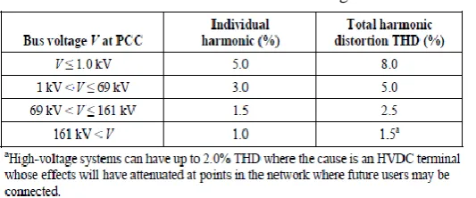
IEEE standard 519 gives the acceptance criteria for voltage and current harmonics. Updated voltage distortion criteria as per standard IEEE 519-2014 provided in below table. The values given at PCC shown in below table are mentioned in percentage of power frequency voltage. Below table is applicable to harmonic voltages having frequencies which are integer multiple of power frequency.
Table1-IEEE 519-2014 harmonic voltage limits
Limit for harmonic current for individual customer is given in standard IEEE 519 as shown in table 2.These standards give the limit for injecting harmonic current in to the system so the resultant voltage distortion for all customers should be in limit.
Table - 2-IEEE 519 Harmonic current limits
In Table – 2, Point of common coupling (PCC)- is the location in the power system near to the user where the system owner can give service to another user. This can possibly resolute by system owner. Customers High voltage step down transformer secondary side and metering end are the probable locations of PCC.
Maximum demand load current (IL)- is given by average of monthly maximum demand in previous 12 months. The limit for harmonic current in the IEEE standard is provided in the percentage of this current.
Short circuit ratio (SCR-Isc/IL) -is calculated as the short circuit current at the PCC (Isc) as fraction of the maximum demand load current (IL). If customer size is small with respect to system then SCR is high. For such a system having high SCR limit for injecting harmonic current is high for customer. Because individual customer can produce less system voltage distortion as impedance of system is less [11]. Next section describes design of shunt passive filter for reducing harmonics.
IV. DESIGNOFSHUNTPASSIVEFILTER
A. DESIGN OF SINGLE TUNE FILTER -
The design of most widely used three filter namely single tune filter which is also called as notch filter, damped high pass filter and C type filter are given in this section. The resonance frequency is given by following equation [6]
fresonant =2π√LC1 = ffundamental√Xc⁄XL
Where,
Fresonant=resonance frequency L=inductance of the filter C=capacitance of the filter
XL=inductive reactance of the filter XC=capacitive reactance of the filter Ffundamental=Fundamental frequency
Step 1: Tune frequency for filter-Filter is tune to the slightly below harmonic frequency to allow for the tolerance in filter elements and system impedance variation. Example for 5th harmonic frequency the filter is tune to 4.7th to allow for the tolerance. Step 2: Size of capacitor bank –shunt passive filter also improve power factor & size of capacitor bank can be calculated as follow
𝑄𝑐
= P × {tan(
cos−1pfactual)
− tan(cos−1pftargeted)Where,
JETIRCQ06031 Journal of Emerging Technologies and Innovative Research (JETIR) www.jetir.org 181 Qc = reactive power to be compensated,
Pfactual = actual power factor,
Pftargeted = power factor to be improved.
Capacitor bank reactance (Xcapacitor) at power frequency is calculated as follow
Xcapacitor =kV
2
Qc
Where, kV-system voltage
Step 3: size of filter inductive reactance –is calculated by using capacitive reactance to trap h harmonic as follows,
XL =Xcapacitorh2
L = XL
2πffundamental
Resistance of reactor is calculated as follow
𝑅 = 𝑋
𝑄𝑓 Where,
X-inductive or capacitive reactance at resonance Qf -Quality factor
Typical values of Qf is in between 15-80 for filters used in industrial & commercial application [6].
B. DESIGN OF SECOND ORDER FILTER
T
he configuration of second order filter is as shown in figure 2(C) it consist of capacitor connected is series with parallelcombination of inductor, resistance. Hence it has 3 design equations from that the values of capacitor and inductor can be calculated same way as specified in design of single tuned filter(step 2 & step 3), need to calculate value of damping resistor only & it can be calculated from the quality factor. Quality factor (Qf) of second order filter is defined as the ratio of resistance to the reactance (inductive/capacitive) of RC parallel circuit at tuned frequency. As Quality factor of this filter is reciprocal of quality factor which is provided in design of single tune filter. Quality factor decides bandwidth that determines sharpness at the tuning frequency & is given by
Qf =RX
Where,
X=XL or XC at tuned frequency
Hence damping resistor can be calculated as below R = Qf × X
For second order or damped high pass filter value of quality factor varies between 0.5-5. Damped high pass filter with high quality factor suppose Qf=5, filtering of harmonic at tune frequency is more definite. But impedance of filter increase gradually for higher frequency hence filter is less effective for higher harmonic order. If the Qf is low as Qf=0.5, filtering of harmonic at tune frequency is good and impedance of filter is constant for increasing value of frequency hence filtering of higher order harmonic is also achieved well.
If Qf is kept very high to mitigate the tune harmonic very well suppose Qf from range10-50 in such a case resistance increase and losses will become very high.
C. DESIGN OF C-TYPE FILTER
It consists of main capacitor C1 connected in series with parallel combination of C2+L & resistance R. Hence four design equations are presents. The value of main capacitor & inductor can be calculated same way as in single tuned filter. The second capacitor tuned to inductor at power frequency to reduce power frequency loss & is calculated as below,
C1 =V2× 2πfQ
L = 1
[(2πfr)2
∗ C1] R = 𝑄𝑓 × 2πfr × L
C2 =(V × 2πf)1 2× L
Where,
Q = reactive power produced by filter at power frequency V = voltage at which filter is to be installed
JETIRCQ06031 Journal of Emerging Technologies and Innovative Research (JETIR) www.jetir.org 182 V. HARMONICFILTERRATING-
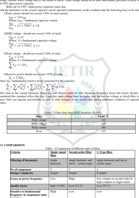
After completing harmonic analysis and sizing components of shunt passive filter accordingly the capacitor ratings peak voltage, current, RMS voltage and kVAR needs to check. These ratings should be in limit individually provided in IEEE standard 18-1992 shunt power capacitor.
IEEE std 18-1992 “shunt power capacitor states that
With the harmonics in the system capacitor can be operated continuously on the condition that the following have to be satisfied 1) Peak current-should not exceed 130% of rated current.
𝐼𝑃𝐸𝐴𝐾 < 1.8𝐼𝐹𝑢𝑛𝑑
Where, IFund = fundament capacitor current 𝐼𝑅𝑀𝑆
𝐼𝐹𝑢𝑛𝑑= √1 + 𝑇𝐻𝐷𝑖
2≤ 1.8
2) RMS voltage –should not exceed 110% of rated 𝑉𝑅𝑀𝑆 < 1.1𝑉1
Where, V1=fundamental capacitor voltage 𝑉𝑅𝑀𝑆
𝑉1 = √1 + 𝑇𝐻𝐷𝑣
2≤ 1.1
3) Peak voltage –should not exceed 120% of rated 𝑉𝑝𝑒𝑎𝑘 < 1.2𝑉1
Where, V1=fundamental capacitor voltage
∑ 𝑉𝑐ℎ < 1.2𝑉1 ℎ
4) Reactive power should not exceed 135% of rating 𝑄𝑐 < 1.35𝑄𝑐1
Where Qc1=fundamental reactive power generated by the capacitor 𝑄𝑐
𝑄𝑐1= ∑ ℎ (
𝑉ℎ
𝑉1)
2
= ∑1
ℎ ℎ=1 ℎ
(𝐼ℎ 𝐼1)
2
= ∑𝐼ℎ𝑝𝑢
2
ℎ ℎ=1
≤ 1.35
Filter tune to the certain harmonic frequency will observe parts of other harmonic frequency hence this factor should also be considered this standard reflect that fact. Capacitor rated voltage must be higher than the bus bar voltage at which filter is placed hence filter can operate successfully in case of over voltages in the system and during unbalance condition of capacitor bank (filter).
Table - 3 Filter duty limit IEEE Standard 18-1992
Duty Limit %
Peak voltage 120
RMS voltage 110
Peak current 180
Kvar 135
VI. COMPARISION
Table - 4 Comparison of different types of filter
Criteria Single tuned
filter
Second order filter C-Type filter
Filtering of harmonics single harmonic
single harmonic and above certain range
single harmonic and above certain range
No of component 2 3 4
Design Complexity Simple Simple Complex
Losses at power frequency Less High less compare to second order & high compare to single tuned Quality factor high (15-80) Low (0.5-5) Low (0.5-5)
Sensitive to fundamental frequency & component value variation
JETIRCQ06031 Journal of Emerging Technologies and Innovative Research (JETIR) www.jetir.org 183 VII. CONCLUSION
In this paper reviewed different shunt passive filter for reducing harmonics such as single tuned filter, second order high pass filter & C-type filter. The design of each method is presented. And finally comparison conducted on different point such as performance, design complexity and losses.
Though passive filter is having low cost, simplicity, reliability & efficiency it has limitations such as, resonance problem, fixed compensation character, possible overload and poor dynamic behaviour.
REFERENCES
1. IEEE Standard 519-1992 IEEE Recommended Practice & Requirements for Harmonic control in Electric Power System. 2. IEEE Standard 519-2014 IEEE Recommended Practice & Requirements for Harmonics Control in Electric Power System. 3. IEEE STD 18-1992, IEEE Standards shunt power capacitor
4. A. B. Nassif, W. Xu, W. Frietas, “An investigation on the selection on filter topologies for passive filter applications”, IEEE Transaction on power delivery, vol.24, no.3, July 2009
5. IEEE standard 399TM-1997 IEEE recommended practices for industrial & commercial power system analysis. 6. IEEE STD141-1993 IEEE Recommended Practices for Electrical Power Distribution for Industrial Power Plant 7. Power quality by N Shankaran
8. Xin Li, WilsunXu, Tianyu Ding, “Damped High Pass Filter-New Filtering Scheme for Multi pulse Rectifier System” IEEE transaction on power delivery, vol. 32, no.1, February-2017
9. ModiPramod s, Joshi S. K..,”An investigation on harmonics and active reactive power of asymmetrical operation of 12 pule converter and mitigation of harmonics”
10. Mark F. McGranaghan, Dave Mueller, “Designing harmonics filters for adjustable speed drives to comply with new IEEE-519 Harmonics limit ” J. C. Das, PE, Passive Filters-potentialities and limitations, IEEE Transaction on industry application, Jan-Feb 2004, 232-241.
11. Angelo Baggini, hand book of power quality, John Wiley and sons. Lt
12. Young Sik Cho, Hangu Cha “single tuned passive harmonics filter design considering variances of tuning and quality factor” journal of international council on electrical engineering vol. 1, no. 1, pp. 7-13,2011