JETIR1504086 Journal of Emerging Technologies and Innovative Research (JETIR) www.jetir.org 1304
Use of Multi-hole Nozzle in CI Engine-A Comparison
of Efficiency
Nishanth V Kamat
1, Sudesh Bekal
2, Ravinarayan Bhat N
31M.Tech Scholar, Dept.of Mechanical Engineering NMAMIT, Nitte, Udupi-574 110, India
2Professor, Dept.of Mechanical Engineering NMAMIT, Nitte, Udupi-574 110, India
3Professor, Dept.of Mechanical Engineering Srinivas Institute of Technology, Mangalore, India
Abstract
—
Use of biodiesel or vegetable oil in IC engine has been tried by many researchers. It has been found that the best efficiency is obtained with 20% blend of biodiesel in biodiesel-diesel combination. However in order to obtain complete benefit of biodiesel use, the engine should be made to work on higher percentage of biodiesel or solely on biodiesel. The authors speculate that such a scenario can be arrived at by making certain modification in the engine. In this work an attempt has been made to see if changing the injection nozzle configuration could result in the use of higher percentage of biodiesel in the blends with comparable efficiency. 3, 4 and 5-hole nozzle configurations were tried. From the result it is found that for higher percentage blend of biodiesel (60% and 100%) 3-hole nozzle configuration found to be the best. However 5-hole nozzle resulted in better results than that of 4-hole nozzle configuration.Keywords- Biodiesel, Diesel engine, injector nozzle, performance
I. INTRODUCTION
The depletion in the petroleum reserves has prompted use of vegetable oil and its esters in IC engines. The raw vegetable oil with its high viscosity would result in high level of smoke and operational problems if used as fuel in diesel engines. Therefore the esterified version of the vegetable oil is being experimented with. However there are certain issues of use of chemicals and energy for the production of vegetable oil esters. Presently as diesel is available most of the research evolves around use of mixture of petro-diesel and vegetable ester blend. Further it is found from the literatures that best possible efficiency obtained with 20% blend of ester and diesel and this efficiency generally less than efficiency obtained using diesel engine [1, 2]. There are two aspects needs to be considered, 1. The problem of low percentage usage of biodiesel, that is at 20% biodiesel blend not much saving in diesel is secured. 2. In the forcible future diesel is going to get exhausted and then the engine will have to be run on 100% or higher blend of biodiesel. Considering these scenario it becomes imperative to work with higher blends or solely on biodiesel. Hence focused research has to be undertaken in ensuring the same at comparable efficiency.
Most of the research done till now are associated with no modification in the engine system. In this work experiment have been conducted by making changes in the engine system such as use of different nozzle to see the possibilities of use of higher percentage of blend in IC engine.
In the present investigation biodiesel was prepared from pongamia oil and blended with diesel in various volumetric proportions. The prepared blends were fueled in the engine test rig. The performance and combustion characteristics were analyzed on a four stroke single cylinder direct injection diesel engine. The properties of pongamia oil methyl ester compared with diesel as shown in Table.1
TABLE 1
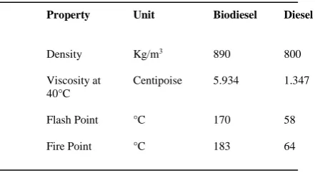
PROPERTIES OF BIODIESEL COMPARED WITH DIESEL
Property Unit Biodiesel Diesel
Density Kg/m3 890 800
Viscosity at 40°C
Centipoise 5.934 1.347
Flash Point °C 170 58
Fire Point °C 183 64
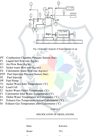
JETIR1504086 Journal of Emerging Technologies and Innovative Research (JETIR) www.jetir.org 1305 Fig.1 shows the schematic line diagram of the experimental set up and its specification are given in Table 2.The setup consists of single cylinder, four stroke, Diesel engine connected to eddy current type dynamometer for loading. It is provided with necessary instruments for combustion pressure and crank-angle measurements. These signals are interfaced to computer through engine indicator for Pϴ-PV diagrams. Provision is also made for interfacing airflow, fuel flow, temperatures and load measurement. The set up has stand-alone panel box consisting of air box, fuel tank, manometer, fuel measuring unit, transmitters for air and fuel flow measurements, process indicator and engine indicator. Rotameters are provided for cooling water and calorimeter water flow measurement. The setup enables study of engine performance for brake power, indicated power, frictional power, BMEP, IMEP, brake thermal efficiency, indicated thermal efficiency, Mechanical efficiency, volumetric efficiency, specific fuel consumption, A/F ratio and heat balance.
Fig.1.Schematic diagram of Experimental set up
PT Combustion Chamber Pressure Sensor (bar) F1 Liquid fuel flow rate (kg/hr)
F2 Air Flow Rate (kg/hr)
F3 Jacket water flow rate (kg/sec) F4 Calorimeter water flow rate (kg/sec) PTF Fuel Injection Pressure Sensor (bar) FI Fuel Injector
FP Fuel Pump
T1 Jacket Water Inlet Temperature (°C) LC Load Cell
T2 Jacket Water Outlet Temperature (°C) T3 Calorimeter Inlet Water Temperature (°C) T4 Outlet Water Temperature at Calorimeter (°C) T5 Exhaust Gas Temperature before Calorimeter (°C) T6 Exhaust Gas Temperature after Calorimeter (°C)
TABLE 2
SPECIFICATION OF DIESEL ENGINE
Make Kirloskar
Model TV1
Type Direct injection
Bore × Stroke (mm) 87.5 × 110
Compression ratio 17.5:1
Cubic capacity 661 cc
Rated power 5.2 kw
Rated speed 1500 rpm
JETIR1504086 Journal of Emerging Technologies and Innovative Research (JETIR) www.jetir.org 1306 TABLE 3
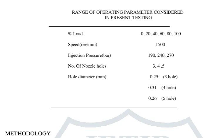
RANGE OF OPERATING PARAMETER CONSIDERED IN PRESENT TESTING
% Load 0, 20, 40, 60, 80, 100
Speed(rev/min) 1500
Injection Pressure(bar) 190, 240, 270
No. Of Nozzle holes 3, 4 ,5
Hole diameter (mm) 0.25 (3 hole)
0.31 (4 hole)
0.26 (5 hole)
III. METHODOLOGY
Experiments were conducted on 4 stroke, single cylinder diesel engine with compression ratio of 17.5 and a rated speed of 1500 rpm controlled by the governor. An injection angle of 23° bTDC and an injection pressure of 190 bar as the optimized values for diesel fuel operation. The engine was first ran with neat diesel at loading conditions of 0%, 20%, 40%, 60%, 80% and 100%. At each load trials, the engine was allowed to reach steady state condition by running it for 2 minutes before taking the readings. At each loading condition, performance parameters namely speed, exhaust gas temperature, brake power, were measured under steady state conditions. With the above experimental results, total fuel consumption, brake specific energy consumption and brake thermal efficiency were calculated.
Engine was then ran with fuel variants of B20 (20% pongamia oil and 80% diesel), B40(40% pongamia oil and 60% diesel), B60(60% pongamia oil and 40% diesel) and B100(100% pongamia oil) for 3 hole, 4 hole and 5 hole injector at 190, 240 and 270 bar pressure. Performance parameters at each loading condition were measured.
IV. RESULTSANDDISCUSSIONS
A. Brake Thermal Efficiency
Experimental results indicate that Brake thermal efficiency (BTE) increased with injection pressure. Fig.2 shows the variation of brake thermal efficiency with injection pressure for 3- hole injector at 80% load. Brake thermal efficiency for B100 was better of all the blends and it was maximum for 270 bar pressure. At lower pressures, due to coarse spray formation, poor atomization of fuel during injection, the thermal efficiency decreased. When the injection pressure was increased, because of smaller droplet sizes, fine spray was formed during injection.Due to this, physical delay period reduced which resulted in better combustion and higher brake thermal efficiency. As the percentage of biodiesel increased in the fuel the brake thermal efficiency also increased. This may be due to more oxygen content in the biodiesel leading better combustion of fuel. Fig.3 shows the variation of brake thermal efficiency with injection pressure for 4- hole injector at 80% load, because of increase in hole diameter, more fuel was consumed compared to other injectors, which led to incomplete combustion. It can be observed from fig. 3 that the brake thermal efficiency is substantially less for all the fuel variants, with 4- hole injector. This can be attributed to the fact that more fuel is injected as shown in table 4, with quantity of air remaining the same, resulting incomplete burning of the fuel. However the brake thermal efficiency for B100 was better of all the blends and it was maximum at 270 bar pressure. Fig.4 shows the variation of brake thermal efficiency with injection pressure for 5- hole injector at 80% load, the brake thermal efficiency for the blend B100 was better of all other blends.
TABLE 4
TOTAL FUEL CONSUMPTION FOR DIFFERENT
INJECTORS AT 80% LOAD
No of holes in injector
Type of fuel used
Total fuel
consumption(kg/hr)
3 Hole Diesel
B20 B40 B60 B100
JETIR1504086 Journal of Emerging Technologies and Innovative Research (JETIR) www.jetir.org 1307
4 Hole Diesel
B20 B40 B60 B100 3.57 2.98 2.97 2.70 2.98
5 Hole Diesel
B20 B40 B60 B100 1.98 1.98 1.98 2.12 1.98
Fig.2- Variation of brake thermal efficiency with injection pressure at 80% load for diesel and pongamia methyl ester blends for 3 hole injector
Fig.3- Variation of brake thermal efficiency with injection pressure at 80% load for diesel and pongamia methyl ester blends for 4 hole injector
0 5 10 15 20 25 30 35
190 240 270
Brak e th er m al e ff ici en cy (%)
Injection Pressure (bar)
DIESEL B20 B40 B60 B100 0 2 4 6 8 10 12 14
190 240 270
B ra k e th er mal e ff ic ie n cy ( %)
Injection Pressure (bar)
DIESEL
B20
B40
B60
JETIR1504086 Journal of Emerging Technologies and Innovative Research (JETIR) www.jetir.org 1308 Fig.4- Variation of brake thermal efficiency with injection pressure at 80% load for diesel and pongamia methyl ester blends for 5 hole injector
B. Exhaust Gas Temperature
Exhaust gas temperature was found to be marginally more for biodiesel operation than diesel at all injection pressures. In biodiesel operation the combustion is delayed due to higher physical delay period. As the combustion is delayed, the injected biodiesel fuel particles may not get enough time to burn completely near TDC, hence consequently after burning may occur and hence there is an increase in the exhaust temperature. Fig.5. shows the variation of exhaust gas temperature with injection pressure for 3-hole injector at 80% load, the exhaust gas temperature was maximum for the blend B40. It can be observed that the exhaust gas temperature decreased for higher injection pressures. It decreased substantially when the injection pressure was increased from 190 bar to 240 bar and 270 bar. At higher injection pressures, combustion improved due to finer break up of fuel droplets providing more surface area and better mixing with air which resulted in decrease in exhaust gas temperature at higher injection pressure.Fig.6. shows the variation of exhaust gas temperature with injection pressure for 4- hole injector at 80% load, due to increase in hole diameter, more fuel was introduced with less quantity of air which resulted in incomplete combustion with more heat release hence maximum exhaust gas temperature was recorded for 4 hole injector than other injectors. Fig.7.shows the variation of exhaust gas temperature with injection pressure for 5- hole injector at 80% load, the exhaust gas temperature for the blend B100 was maximum. This may be due to the more oxygen content in the biodiesel which increased the exhaust gas temperature.
Fig.5- Variation of exhaust gas temperature with injection pressure at 80% load for diesel and pongamia methyl ester blends for 3 hole injector 0
5 10 15 20 25
190 240 270
Brak
e
th
er
mal
e
ff
ici
en
cy
(%)
Injection Pressure (bar)
DIESEL
B20
B40
B60
B100
360 370 380 390 400 410 420 430
190 240 270
Ex
h
au
st
g
as t
emp
er
at
u
re
(
°C)
Injection Pressure (bar)
DIESEL
B20
B40
B60
JETIR1504086 Journal of Emerging Technologies and Innovative Research (JETIR) www.jetir.org 1309 Fig. 6 Variation of exhaust gas temperature with injection pressure at 80% load for diesel and pongamia methyl ester blends for 4 hole injector
Fig. 7-Variation of exhaust gas temperature with injection pressure at 80% load for diesel and pongamia methyl ester blends for 5 hole injector
V. CONCLUSION
The performance tests were carried on a single cylinder, four stroke diesel engine and the experiments were conducted on the engine which was fuelled with diesel, B20, B40, B60 and B100.
The brake thermal efficiency for the blend B100 was found to be maximum (32.74%) of all the fuel variants including diesel and it was maximum for 3- hole injector at 270 bar pressure because of smaller fuel particles at higher injection pressure which led to proper mixing of fuel and air, resulting in higher brake thermal efficiency.
The exhaust gas temperature was maximum for all the biodiesel blends and it decreased with the increase in injection pressure.
The result shows that for higher percentage blend of biodiesel 3-hole nozzle configuration found to be the best. However 5-hole nozzle resulted in better results than that of 4-hole nozzle configuration.
It has been observed that engine performed better with the 3-hole injector at 270 bar injection pressure for all the fuel variants, with the air supply, injection advance and injection pressures maintained at the engine manufacturer’s prescribed values.
REFERENCES
[1] R.Murali Manohar, M.Prabhahar, and Dr.S.Sendil velan, Vikash Kumar Choudhary, “Thermal and emission properties of engine fueled with Diesel and
Bio-Diesel blends of B20N, B80N, B20K and B80K”, International Conference On Advances In Engineering Science And Management, ICAESM, 2012, pp. 111-115.
450 460 470 480 490 500 510
190 240 270
Ex
h
au
st
g
as t
emp
er
at
u
re
(
°C)
Injection Pressure (bar)
DIESEL B20 B40 B60 B100
410 420 430 440 450 460 470 480
190 240 270
Ex
h
au
st
g
as t
emp
er
at
u
re
(
°C)
Injection Pressure (bar)
DIESEL
B20
B40
B60
JETIR1504086 Journal of Emerging Technologies and Innovative Research (JETIR) www.jetir.org 1310
[2] M.Venkatraman, and G.Devaradjane,“Experimental Investigation of Effect of Compression Ratio, Injection Timing and Injection Pressure on the Performance
of a CI engine Operated with Diesel- Pongamia Methyl Ester Blend”, IEEE, 2010, pp. 117-121.
[3] Pravin Madane, Ashok Pise, and Sandesh Chougule, “Properties of Biofuels and their Diesel Blends as a Fuel for C.l. Engines”, International Conference On
Advances In Engineering, Science And Management, lCAESM, 2012, pp. 255-262.
[4] S. Mirheidari, J. Mohammadpour, K. M. Grigoriadis, and M. A. Franchek, “Biodiesel Blend Estimation Based on Fuel Consumption and Engine Power”,
American Control Conference, 2010, pp. 3021-3026.
[5] T.Pushparaj, C.Venkatesan, and S.Ramabalan, “Emission Studies on Karanja Biodiesel Fuelled Diesel Engine with Ethanol as Additive”, International
Conference on Advances In Engineering, Science And Management, ICAESM, 2012, pp. 263-268.
[6] R. Senthilkumar, K. Ramadoss, and M. Prabu, “Emission And Performance CharacteristicS of Single Cylinder Diesel Engine Fuelled With Neem Biodiesel”,
International Conference On Advances In Engineering, Science And Management , lCAESM, 2012, pp. 353-359.
[7] Ning Ding, Wei-min Gao, Ming Chen, and Xiao-mao Zhang, “Spray Characteristics of New Generation Multi-hole Injector for Spark-ignition Gasoline
Engines with Direct Fuel Injection”, International Conference on Information Engineering, WASE, 2010, pp. 265-269.
[8] S. K. Nayak,B. P. Pattanaik , P. Ghosh , and M. Ukamanal, “Experimental Investigation on a Diesel Engine Fuelled with Biodiesel Produced from Waste