Experimental implementation of a real-time token-based
network protocol on a microcontroller
Ferdy Hanssen, Robert Krikke, Bert Baron, Pierre G. Jansen, Hans Scholten Distributed and Embedded Systems group
Faculty of Electrical Engineering, Mathematics, and Computer Science — University of Twente PO-Box 217, 7500 AE, Enschede, the Netherlands
Fax: +31 53 489 4590 E-mail: [email protected]
Abstract— The real-time token-based RTnet network protocol has been implemented on a standard Ethernet network to investigate the possibility to use cheap com-ponents with strict resource limitations while preserving Quality of Service guarantees. It will be shown that the proposed implementation is feasible on a small network. For larger networks a different approach is necessary, using delegation by means of proxies. A delegation proposal will be discussed. For small networks it is possible to use a PIC microcontroller in combination with a standard Ethernet controller to run the RTnet network protocol. As more systems are added to the network the performance of this combination becomes insufficient. When this happens it is necessary for the microcontroller to delegate some tasks to a more powerful master and to organize a low-level com-munication protocol between master and slave.
I. Introduction
Digital networks are gradually being introduced into our homes. Already we use networks to connect our home computers to the internet. Advanced cli-mate control systems use a network to gather infor-mation from the various sensors in the house and ad-just the in-house climate to the inhabitants’ wishes. Currently these networks operate independently. In the not too distant future these networks will be inte-grated into one. This single network will support the various multimedia, data, and control needs.
To be able to mix all these kinds of traffic on one network, it needs to be possible to provide quality of service guarantees. Applications need to be able to re-serve a portion of the available bandwidth to transmit multimedia data. At the same time it must be possible to allow best-effort traffic to use as much bandwidth as is available. The application area of such a network is not just the home, it can also be put to use in an industrial environment, inside a common-bus switch or to let individually clocked components inside an integrated circuit communicate.
In this paper we will present an experimental
imple-mentation of a real-time network protocol on a stan-dard microcontroller. This protocol is called RTnet. The RTnet protocol is used to provide QoS for media streams on a network. But it can also be used for com-mand and control signals on that same network, so it is important to research the possibility of implement-ing this protocol, or some variant, on small processors that are used to control sensors and actuators.
After a short overview of the protocol, we will show how the microcontroller implementation differs. Then we will show a sample application and discuss the pros and cons of this implementation.
II. Operation of RTnet
RTnet can run on any single-segment network which supports a broadcast capability. The current proto-type is based on the CSMA/CD Ethernet protocol [1]. In effect this means that RTnet can be built on any regular Ethernet hardware by only changing the pro-tocol software. RTnet creates a deterministic network by allowing only one node to use the network at any given time. RTnet is a token-based protocol, just like Rether [2], developed at SUNY Stony Brook.
Rether distributes its token among the nodes in a simple, static Round-Robin manner. RTnet, however, uses a more sophisticated algorithm, where the token is allocated to nodes according to their bandwidth de-mands. A pre-emptive earliest deadline first (EDF) scheduler is used to determine the route a token fol-lows in the network. This type of scheduler has the advantage over other schedulers that it can achieve a 100% utilization. However, in case of overload its per-formance will degrade dramatically. It is also possible to employ other schedulers, e.g. rate monotonic.
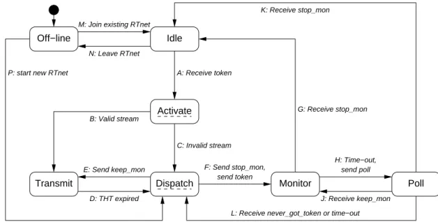
Every node operates according to the state-transition diagram in figure 1. This description does not mention the clock synchronization or detailed de-scriptions of all possible fault situations. There are seven states, of which the statesactivate anddispatch
Monitor Poll Transmit Idle Off−line F: Send stop_mon, send token Activate Dispatch send poll H: Time−out, E: Send keep_mon
D: THT expired J: Receive keep_mon L: Receive never_got_token or time−out N: Leave RTnet A: Receive token K: Receive stop_mon C: Invalid stream B: Valid stream G: Receive stop_mon M: Join existing RTnet
P: start new RTnet
Fig. 1. State-transition diagram of RTnet
are special. In these two states the node may not stay any longer than strictly necessary.
A node is theactive node when it is the token holder (in stateactivate,transmit, ordispatch). When a node receives the token (transitionA), it will check whether its associated stream is still valid. If not, a reschedule is necessary (transition C), otherwise the node will start transmitting (transitionB).
The active node may use the network for some time:
the token holding time (THT). The THT is
deter-mined by the scheduler (state dispatch) and is likely to be different for each stream. Typically the node will send one frame of a periodic multimedia stream. Note that our network works with constant-bit-rate streams; for variable-bit-rate streams several mapping techniques can be used [3].
The EDF scheduler is distributed over the nodes and the token contains the shared scheduling infor-mation for all of them. Each node will keep backups of the schedule though. If a node has the token and it wants to add or remove a stream, it calculates a new schedule and acts upon it. Before a new stream may be added the node does an EDF feasibility test to determine if the newly added real-time stream will meet its deadlines without making other streams miss theirs. The EDF feasibility test is simple [4]: the to-tal of bandwidth utilizations by all streams may not exceed 100%. However, only 80% of network band-width is dedicated to real-time (multimedia) commu-nications, the rest is used for non-real-time purposes. Actually, the maximum bandwidth is slightly less be-cause of the token transmission and Ethernet packet
overhead.
At the expiry of the THT for a certain stream (tran-sition D), the scheduler computes the next stream which may use the network. When the new stream is on the already active node, it informs the monitor of this (transitionE) and starts transmitting.
When the scheduler at the active node decides that another node must become active it computes the new THT, stores the global schedule information in the token and sends the whole package to the new node (transitionF). This is a critical action and it should not occur that the token becomes lost, or worse, dupli-cated. When a token is lost the schedule is lost too and the network stalls. Duplicated tokens mean that more than one node will make schedules and collisions will occur, causing deadline misses and non-deterministic behaviour. To correct this kind of misbehaviour the concept of a monitor is introduced while restricting the token size to always fit the token in a single net-work packet.
When the active node relinquishes the token, this node becomes the monitor for the new active node. Monitoring is a three step process.
1. The monitor sends the token to the new active node.
2. This active node is now in the statetransmitfor the duration of the THT. While the active node transmits, the monitor waits for a reply from the active node. It sets a timer for the duration of the THT.
3. At the end of the THT the active node must send a reply to the monitor signalling that it is still alive. This reply can be one of two possibilities.
(a) When the active node needs to keep the token longer, it will reply with a keep monitoring message (keep mon) with a new THT. The monitor will reset its timer and start waiting for a new reply from the active node.
(b) When the active node needs to forward the to-ken, it will reply with a stop monitoring message (stop mon). The old monitor now ends its activity, the old active node becomes monitor, and the new ac-tive node begins transmitting. Then the process starts all over.
Many things can go wrong. When the monitor times out, it sends a poll (transition H). When the original reply was lost, it will receive a copy of that reply (transition J or K). When the token was lost it will receive a message stating the token was never delivered (never got token). When nothing is received after a short wait, the monitor will mark the active node as dead and remove it from the node list. In both cases a reschedule is necessary (transitionL).
A node starts in theoff-line state and will join an existing RTnet network (transitionM) or create a new one if an RTnet network does not yet exist (transi-tionP). To properly leave an RTnet, a node will have to remove itself from the token when it is the active node and act as monitor during the next round. Only after that, when it is idle, it may leave the RTnet and become off-line again (transition N).
III. RTnet on a microcontroller
The prototype hardware has been designed with available, cheap components in mind to resemble a device as it may be built in practice. The main components are a Microchip PIC 16F877 microcon-troller [5] and a Realtek RTL8019AS, NE2000 com-patible, 10Mbit/s Ethernet network interface con-troller (NIC) [6]. Since the amount of memory inside the PIC is limited to 368B, 8KiB of serial, non-volatile FRAM memory [7] was added. An analog tempera-ture sensor is used for a test application, and an RS232 link was added to provide some debugging facilities.
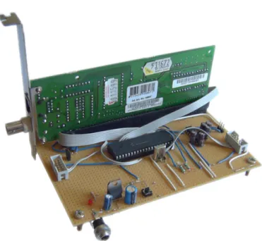
The block diagram of the device is shown in figure2. The number of I/O pins of the microcontroller used for the various connections is denoted with a slash after the description. Figure 3 shows the prototype device as it looks in real life. Note that a standard PC-style interface card was used for the network interface controller.
The first version of the device controlled the NIC in 16-bit mode. However, this hardly performed better than 8-bit mode, as 16-bit data communication has to
sensor serial programminginterface 10Mbit/sEthernet
RTL8019AS network interface controller serial FRAM memory RS232 driver RS232 16F877 PIC microcontroller data /8 address /5 control /2 I²C /2 analog /1 SPI /2 SCI /2
Fig. 2. Block diagram of the device
Fig. 3. Visual impression of the prototype
be done in two bit steps. Operating the NIC in 8-bit mode is only slightly slower than 16-8-bit mode, but saves 8 digital I/O pins on the microcontroller, which can be more useful for certain applications. Also it is possible to use a cheaper microcontroller with less I/O pins than the one we used.
The microcontroller is clocked at 20MHz, which provides us with 5M instructions per second. The communications with the serial FRAM memory oper-ates over an I2C bus clocked at 1MHz. This results in a speed of approximately 100kB/s for continuous memory read or write operations.
The implementation consists of five parts: the driver for the NIC, the driver for the serial memory, a partial RTnet implementation, a partial UDP/IP stack, and a test application. For debugging facilities a simple user interface is included, which allows the device to be controlled over an RS232 link.
RTnet was implemented partially. In particular, the following parts are not (yet) implemented:
• start a new RTnet if one does not exist; • acting as monitor for other nodes;
Idle Off−line Transmit F: Send stop_mon, send token Dispatch N: Time−out
M: Join existing RTnet
D: THT expired A: Receive token
E: Send keep_mon
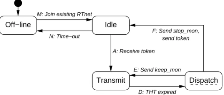
Fig. 4. State-transition diagram of microcontroller imple-mentation of RTnet
• acting on error conditions and performing network recovery.
Figure 4 shows the reduced state-transition diagram for the microcontroller implementation of RTnet.
The NIC driver handles packet reception by polling. Packets are buffered by the NIC in its on-board mem-ory. In this way it is not necessary to use the inter-rupt line of the NIC. Only in two RTnet states the device is polling: off-line and idle. In the state off-line only packets soliciting devices to join an RTnet are accepted, all other packets are discarded. In the stateidle all packets are accepted, unrecognized pack-ets are silently ignored.
When the device is idle and the token is not received in time, i.e. within the token rotation time, the device assumes it is not part of the network any more and will become off-line (transition N in figure 4). When a packet is accepted, it will be processed immediately. Any replies will be queued until the token is received and the RTnet protocol decides they may be sent. E.g. the reply to an ICMPecho request (ping) will be queued for handling during the non-real-time phase of RTnet.
When a token is received, the device enters the state
transmit (transitionAin figure4) and it will send the available data for the active real-time stream. Note that it does not check explicitly if the stream is still valid. If all data is sent, the state dispatch is entered (transitionD) so a new stream may be selected.
In this state the EDF scheduling algorithm is per-formed. If the next stream originates from this device, it will inform the monitor (transitionE) and send the data belonging to this new stream. Otherwise the token is forwarded to the new active node and the de-vice becomes idle again (transition F). Note that in this situation RTnet functions without monitor for a while, since our prototype does not implement moni-tor functionality yet.
The unimplemented states,monitorandpollin par-ticular, are not hard to implement. They do not re-quire a lot of processing time or writable memory, but they do require a fair share of programme mem-ory. The current implementation requires most of the available programme memory however, so the addi-tion of these states would require a fair bit of engi-neering.
The UDP/IP stack implements only the parts needed for the application. It supports sending and receiving IP packets, without support for IP options. It supports sending and receiving UDP packets, where the optional checksum field is not being used. It con-tains a very bare implementation of ARP: only re-quests for the hardware address of the device’s IP are answered. It does not generate ARP requests, it caches the hardware addresses of clients from their real-time stream requests. Furthermore, it supports receiving ICMPecho requests and transmitting ICMP
echo replies. The ICMP checksum of the reply is not calculated, but generated from the checksum of the request. In some cases this leads to an invalid check-sum, but these can be ignored.
A. Test application
The test application turns the device into a sim-ple thermometer. Client applications can request the device to send them the temperature once per sec-ond. To do so they send a non-real-time request over UDP to the device. This will then allocate a real-time stream to that client with a bandwidth of one RTnet timeslice (10ms) of network usage per second. Every measurement from the time of request onwards will then be sent to the client, none will be skipped or duplicated. Multiple clients are supported, even originating on the same node.
Using a timer interrupt the temperature is mea-sured. They are stored in a small buffer, marked with a time stamp. They are sent to the clients in fixed-size UDP packets, with pre-generated headers stored in the external, serial memory. At most one packet is sent every period of one second, which leads to deter-ministic worst-case behaviour.
IV. Advantages and disadvantages of the implementation
In a small RTnet network the prototype implemen-tation works very well. The token is processed cor-rectly and the EDF scheduling algorithm is performed as it should. Non-real-time requests are processed cor-rectly and in a timely manner and real-time streams
are served according to demand.
Every packet received is copied to the serial mem-ory, which operates at approximately 100kB/s. This means that large tokens cannot be processed within the 10ms that is allocated to the device. The token must be processed and the corresponding real-time data must be sent within the scheduler granularity of 10ms, because the token may have to be forwarded again to another node after that time.
The worst-case token processing time has not been extensively analysed. Assuming that processing the token takes about the same amount of time as copy-ing it from and to the serial memory, a token of up to (10ms×100kB/s)/4 = 250B can be processed in time. But this leaves no time for sending any data, so the maximum token size is even less. The current imple-mentation uses a token size of 92B for a network of two nodes and no additional streams. An additional node uses 26B and a real-time stream uses 20B of to-ken space, so our prototype can handle a network of about four nodes with a few real-time streams.
Other large packets, such as large ICMP echo re-quests may also result in timing constraint violations. These violations may lead to elimination of our micro-controller device from RTnet by the active monitor, leading to disruption of service. The problem caused by large non-real-time packets can be avoided by in-specting the packet size before copying it to the serial memory. But the token has to be copied in order to be processed. On the current prototype we have no solution for this. The only possible solution may be in different use of the on-board memory of the NIC.
The current implementation occupies almost all of the available programme memory on the microcon-troller. Size-optimized code, with fewer debugging possibilities, may leave more room for a more com-plete implementation of the RTnet protocol and a dif-ferent application. In the available programme mem-ory it will, however, be hard to fit a complete RTnet implementation together with a reasonable applica-tion.
A. Solutions
The obvious solution for the timing problems of the current prototype is to use a microcontroller with a possibility of connecting directly addressable mem-ory, instead of the serial memory operated over a slow I2C bus. Another solution is the use of a microcon-troller with more internal memory. Since a token will never grow larger than an Ethernet packet, which is 1500B, a memory capacity of 2KiB should be enough
for an RTnet implementation. We estimate that a bandwidth of at least 600kB/s is needed towards the memory and the same bandwidth towards the NIC to build a workable RTnet implementation on a micro-controller with comparable execution capacities. For an efficient RTnet implementation a microcontroller with somewhat more bandwidth towards memory and NIC is needed.
Another solution is to not let the microcontroller operated nodes act as full participants in the RTnet network. Allowing them to delegate their work to a more powerful node results in a simple client-server setup and the ability to use cheaper, less powerful mi-crocontrollers. Such a delegation may be implemented in two possible ways.
The first delegation solution is an implementation of the delegation at application level. In order to make this viable the host application on a powerful node needs some way of knowing which client devices there are and what bandwidth requirements they need. The host may then allocate this amount of bandwidth for itself. Whenever the host obtains the token for this stream, it can inform the client with a single packet command that it may transmit its data for a certain amount of time. This requires the client to not par-ticipate in RTnet at all and to respond and complete its actions within one scheduler timeslice to avoid pre-emption. The client must then never send a network packet on its own, since this could disrupt RTnet op-eration.
The other delegation solution is an implementation at RTnet protocol level. This creates two types of RTnet nodes: “normal” and “light” ones. The “light” ones will associate themselves with a “normal” node, which will act on their behalf in all network commu-nication matters. The main difference between this delegation solution and the previous one is that the network handles light devices in a transparent and standardized manner, which eases application devel-opment. However, this complicates the RTnet proto-col.
V. Conclusions
It has been shown that it is possible to create a working partial implementation of RTnet on a micro-controller and run an application on top of it. How-ever, it cannot support a large network, mainly be-cause of the limited memory bandwidth on the de-vice. For a full RTnet implementation a microcon-troller with a memory bandwidth of at least 600kB/s is needed.
The best solution for the use of microcontroller op-erated devices in an RTnet is probably the use of del-egation. The more complex tasks can then be taken over by a more powerful node in the network. There are many ways to do delegation, so there is much re-search still needed in that area. And it is a real chal-lenge to design a delegation protocol which does not compromise the simplicity of the RTnet protocol.
References
[1] IEEE Standard for Information Technology — Telecommunications and Information Exchange between Systems — Local and Metropolitan Area Networks — Specific Requirements — Part 3: Carrier Sense Multiple Access with Collision Detection (CSMA/CD) Access Method and Physical Layer Specifications, Institute of Electrical and Electronics Engineers, 2002, IEEE Std. 802.3-2002. [2] “Rether web site,”http://www.ecsl.cs.sunysb.edu/rether/. [3] S. V. Anastasiadis, K. C. Sevcik, and M. Stumm,
“Server-based smoothing of variable bit-rate streams,” in Proceedings 9th ACM Multimedia Conference, Ottawa,
Canada, Oct. 2001, pp. 147–158. [Online]. Available:
http://www.acm.org/sigmm/mm2001/ep/anastasiadis/
[4] C. L. Liu and J. W. Layland, “Scheduling algorithms for multiprogramming in a hard real-time environment,” Jour-nal of the ACM, vol. 20, no. 1, pp. 46–61, Jan. 1973. [5] “Microchip PIC 16F877 web site,” http://www.microchip.
com/.
[6] “Realtek RTL8019AS web site,” http://www.realtek.com. tw/search/search.aspx?search=RTL8019AS.
[7] “Ramtron FRAM web site,” http://www.ramtron.com/ doc/AboutFRAM/overview.asp.