Abstract: The paper is discuss on develop and implement a vision based obstacle avoidance for mobile robot using optical flow process. There are four stages in this project which are image pre-processing, optical flow process, filtering, object stance measuring and obstacle avoidance. The optical flow process are an image resizing, set parameters, convert color to grayscale, Horn-Schunk method and change grayscale image to binary number. Next process is a filtering done by smoothing filter then image center will be defined. The maximum distance object from a camera has been set as 20 cm. Therefore, the decisions of the robot to move whether left or right are based on the direction of optical flow. This avoidance algorithm allows the mobile robot to avoid the obstacles which are in different shape either square or rectangular. A friendly graphical user interface (GUI) had been used to monitor the activity of mobile robot during run the systems.
Keywords: Optical flow, smoothing filter, mobile robot, obstacle avoidance
I. INTRODUCTION
Nowadays, robot is one of the most important things to the human. The most famous robot is obstacle avoidance robots where the robot can collision any object surrounding itself therefore it can avoid any damage either the robot structured or component inside the robot. To ensure the robot do not damage because of collision, vision based obstacle avoidance algorithm has been developed. Sensors are most famous, but vision camera have more information that can be provided and increasingly being used by people because the high technology and capability. Because of this characteristic,vision camera has increase to another level for robot perception and become the visual sensing sensor with the highly attractive.
Revised Manuscript Received on 05 February 2019.
Hairol Nizam Mohd Shah, Center for Robotics and Industrial Automation, Faculty of Electrical Engineering, Universiti Teknikal Malaysia Melaka, MALAYSIA
Zalina Kamis, Center for Robotics and Industrial Automation,Faculty of Electrical Engineering, Universiti Teknikal Malaysia Melaka, MALAYSIA
Mohd Fairus Abdollah, Center for Robotics and Industrial Automation, Faculty of Electrical Engineering, Universiti Teknikal Malaysia Melaka, MALAYSIA
Alias Khamis, Center for Robotics and Industrial Automation, Faculty of Electrical Engineering, Universiti Teknikal Malaysia Melaka, MALAYSIA
Mohd Shahrieel Mohd Aras, Center for Robotics and Industrial Automation, Faculty of Electrical Engineering, Universiti Teknikal Malaysia Melaka, MALAYSIA
Mohd Rizuan Baharon, Center for Robotics and Industrial Automation, Faculty of Electrical Engineering, Universiti Teknikal Malaysia Melaka, MALAYSIA
Ifwat Nor Azni, Center for Robotics and Industrial Automation,Faculty of Electrical Engineering, Universiti Teknikal Malaysia Melaka, MALAYSIA
In this paper the objective is to develop and implement the obstacle avoidance algorithm which is the algorithms able to give the instruction to mobile robot platform to move either left or right. This project was based on the distance object either square or rectangular shape from the camera. Optical Flow and Horn-Schuck method is used to obtain the direction of mobile robot.
II. RELATED WORKS
Mobile robot is a common robot that had been used by the human and the most exciting problem in this area is obstacle avoidance. When considering about the obstacle avoidance problem, it actually requires human or people to find a way for the robot to move from one place to the another area that had been specify or program and there are some obstacles that need to be avoid [1,2]. While avoiding
Obstacles, there are some requirements that need to be considered as for example identifying safe and traversable paths which allow the robot to move toward the area. The first mission while doing the robotic research for the mobile robots is to observe the environment. For any autonomous system, observing and sense the surrounding environment is a basic requirement [3,4].
Development of wireless sensor networks (WSN) has become a major in real-world application because of the increase in hardware technology and wireless communications. In real networks, hundreds or thousands of small sensor nodes are frequently use in a sensing field to detect any situation for example external sensors, distance (ultrasound and laser types), vision or proximity sensors [5].
The stereo vision system which can track the object and able to measure the distance from the object in real time is introduced by I. Kim et al. [6]. The method is used trigonometric measurement and the robot kinematics applied to the cross-visual stereo vision system which is fabricated in the mobile robot. Triebel and Burgard [7] are the person that created 3D models of the environment with the highly accurate in a single 3D laser scan based on the edge features. Davison and Murray [8] that proposed an idea active vision is another method for localization and mapping. After comparison, vision systems are much better because of the output and high resolution. Moreover, stereo cameras can observe points of the 3D coordinates more clear based on the scene. Therefore, vision based is highly desirable because of the stable visual landmarks [9]. Instead, a new algorithm for mobile robot obstacle avoidance was implemented by using of cylinder non-circulation circumfluence [10]
Vision Based Obstacle Avoidance for Mobile
Robot using Optical Flow Process
Hairol Nizam Mohd Shah, Zalina Kamis, Mohd Fairus Abdollah,
Alias Khamis, Mohd
In this circumfluence, there are some characters of plane for example flow potential, velocity potential function, and flow function. During the robots obstacle avoidance, this process that is called cylinder circumfluence can be seen. It is the movement of robot which have the similarity to the hydrodynamics using plane flow in two dimensional, which means there are no changes for plane in a vertical direction because in plane there are flow the velocity in each of particle parallels to others fixed plane and also the flow field into the physical quantities. Temperature, velocity, pressure,
and density are some example of physical quantities. In other word, these two elements that are time and coordinates are important element to decide the particle movements.
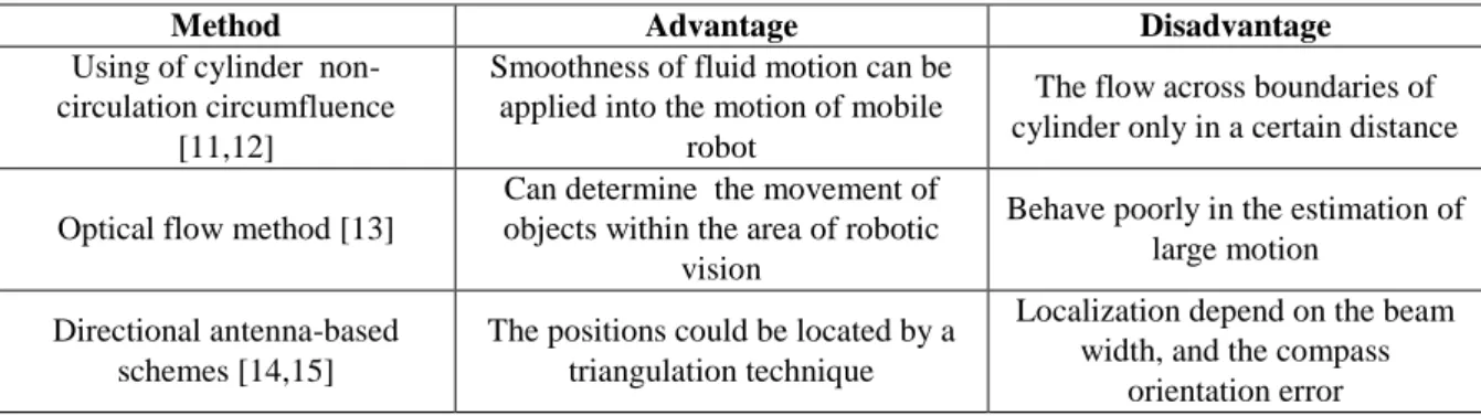
As a conclusion, there is a lot of technique or method that can be use for a mobile robot to avoid the obstacle. Based on the related works the most popular method by user are traversable paths, using of cylinder non-circulation circumfluence, optical flow method, and directional antenna-based schemes. Table 1 show the advantage and disadvantage of method to avoid the obstacles.
Table. 1 Advantage and disadvantage of obstacle avoidance method
Method Advantage Disadvantage
Using of cylinder non-circulation circumfluence
[11,12]
Smoothness of fluid motion can be applied into the motion of mobile
robot
The flow across boundaries of cylinder only in a certain distance
Optical flow method [13]
Can determine the movement of objects within the area of robotic
vision
Behave poorly in the estimation of large motion
Directional antenna-based schemes [14,15]
The positions could be located by a triangulation technique
Localization depend on the beam width, and the compass
orientation error
III. METHODOLOGY
Image Pre processing
The image will be captured by using wireless camera. Then by applied the image pre-processing the unwanted pixels and isolated the boundaries will be removed. In this process, no need the region of interest (ROI) for reduced zone of the target object location. The object image is taken in RGB images. with the maximum distance around 20 cm. Figure 1 show the object in RGB image.
Fig.1 Example of object with RGB images Optical Flow Process
Optical flow is a movement of pixels between images of object. The motion field is a motion or movement of any
object that had been captured by the camera. However, optical flow is just the image of “scene flow” that is based on motion or movement of object that had been captured. To calculate the optical flow, it needs to understand this incongruity as arising from either properties of the scene or error in the optical flow technique. Therefore we used this step to obtain the optical flows.
Step 1: Image Resizing
In image execution, accuracy of the performance is an
send to component in the images processing. Therefore, the simulation mode will receives sequence of the reality world. Step 2: Set Parameters
There are several things to consider in set parameters. Firstly, the relative arrow and iteration of estimation need to adjust. By apply alpha as 10 and iteration as 10, it can balance the arrow and estimation. Then, the amount of arrow will be set by resize it to 20 and scale size of arrow will be set to 30. Here we used 30 values for scale size of arrow because is not too big or too small.
Step 3:Convert color to grayscale
The grayscale image is used to provide any related confidence measure. The confidence measure error require in optical flow calculation in image reconstruction. Figure 2 show the grayscale image of the object.
Fig.2 Grayscale Image
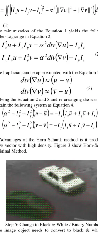
Step 4: Horn-Schunk Original Method
Horn Schunk is another method of optical flow. It shows the flow field of whole image object that are movement either it can be to the left or right. The Horn-Schunck algorithm assumes smoothness in the flow over the whole image. Thus, it tries to minimize distortions in flow and prefers solutions which show more smoothness. The flow is formulated as a global energy functional which is then sought to be minimized. This function is given for two-dimensional image streams as in Equation1.
I
u
I
v
I
u
v
dxdy
E
x y t 2
2||
||
2||
||
2 (1)The minimization of the Equation 1 yields the following Euler-Lagrange in Equation 2.
y t y y x t x y x xI
I
v
div
v
I
u
I
I
I
I
u
div
v
I
I
u
I
2 2 2 2
(2)The Laplacian can be approximated with the Equation 3.
v
v
u
div
u
u
u
div
(3) Solving the Equation 2 and 3 and re-arranging the terms, weobtain the following system as Equation 4.
x y
y
x y t
t y x x y xI
v
I
u
I
I
v
v
I
I
I
v
I
u
I
I
u
u
I
I
2 2 2 2 2 2
(4)Advantages of the Horn Schunk method is it produce a flow vector with high density. Figure 3 show Horn-Schunk Original Method.
Fig. 3 Horn-Schunk Original Method
Step 5: Change to Black & White / Binary Number The image object needs to convert to black & white or binary number known as pixel neighborhood. To determine the adjacency a fixed of gray levels in object image will be used. Therefore, the object will present as 1 and non-object as 0. Table 2 and Table 3 shows the pixel neighborhood that has object in the images.
Table. 2 Pixel neighborhood that object in the middle
Table. 3 Pixel neighborhood that object at the left and right side
Filtering Process
Smoothing filters is used in noise reduction [16,17] and blurring the image of the object. During the filtering process, blurring image need to apply to remove a small particle that are not necessary from the image and strengthen the gap of the line in the image.
Sharp transition can be formed by noise and side object in the image. But it will be reduced if there any changing the value of pixel in the image. Therefore, smoothing spatial filter can used for reduce the noise and blurring.
The brightest and darkest of image depend on the threshold value. If the threshold value nearer to the 0, the image will become brightest or white. But the image will become darkest or black if the threshold value nearer to the 1. Figure 4 and Figure 5 shows results image with refer the threshold value 0.3 and 0.8.
Fig. 4 Image with threshold value 0.3
Fig. 5 Image with threshold value 0.8 Measure the Distance
Step 1: Set the Distance
The distance is set at 20 cm form camera to object by draw the rectangle and present the distance. The rectangle is used to find the object area which the formula is width x height [18]. The AGC or Automatic Gain Control need to adjust to find the whitest object in a whole image. Therefore, if there any whitest objects in the image, a rectangle box will be formed. This rectangular box can obtain the distance.
Step 2: Calculate the object area
The area of object is then need to calculated by using the Equation 5. This area is important during optical flow and Horn Schunk method process.
Area= height x width (5) Obstacle avoidance
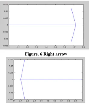
In obstacle avoidance approach, an action taken by mobile robot is based on the quantity number of flow. Numbers of flow are the main element to determine whether to move left or right.
If the numbers of flow are more to the right, the mobile robot movement goes to right. Then the numbers of flow are more to the left thus an action take will move to left. Figure 6 and Figure 7 shows the arrow with refer to right and left.
Figure. 6 Right arrow
Figure. 7 Left arrow IV. RESULTS
To test the optical flow process there required two images with different object location. The first image knows as initial image and second image as the current image. Figure 8 and Figure 9 are show object image before and after it has been moved in black & white and color background. The optical result is show in Figure 10 where the bonding box and centre of the object are represented in red color.
Fig. 8 Image before object moved (a) black and white background (b) color background
Fig.9 Image after object moved (a) black and white background (b) color background
Fig.10 Optical flow result (a) black and white background (b) color background
Figure.11 show an object in a rectangular shape had been captured by using a wireless camera. A bonding box with a red line automatically appear after executed the start image acquisition button. The bounding box is used to obtain the size of the object [19]. The area of the object will be calculated during the object distance 20 cm from the camera as show in Figure 12.
Fig. 11 Rectangular obstacle object shape
Fig. 12 Area calculation process
The movement of mobile robot is based on the direction of the optical flow. If there is more direction of optical flow to the right, then
the mobile robot will move to the left and otherwise. Figure 13 show the decision that the mobile robot will move to the left and right.
(b)
(a)
(b)
(a)
(b)
Fig. 13 Mobile robot movement (a) left (b) right
V. CONCLUSIONS
As a conclusion, vision based obstacle avoidance algorithm for wireless mobile robot can be developed by using optical flow method. This method starts with image pre-processing, the optical flow process and filtering process. The object distance was set within 20 cm to the wireless camera. The results show that the mobile robot able to move either to the left or right based on the direction of optical flow. For Further works, besides using the rectangular object shape it can be used circle or triangular obstacle object shape. However, the result can be improved if the object distance can be more than 20 cm.
Acknowledgement
The authors are grateful for the support granted by by Center for Robotics and Industrial Automation, Universiti Teknikal Malaysia Melaka (UTeM) in conducting this research through grant PJP/2018/FKE(4C)/S01605 and Ministry of Higher Education.
REFERENCES
1. X. Cao and H. Sun, “ Establish the Special Virtual Manipulator Model for Mobile Robot Obstacle Avoidance and Path Planning”, Proceedings of International Conference on Information Acquisition, pp. 511-516, 2007.
2. Hairol Nizam Mohd Shah, Mohd Zamzuri Ab Rashid, Nur Maisarah Mohd Sobran, Rozilawati Mohd Nor, Zalina Kamis “Autonomous Mobile Robot Vision Based System: Human Detection By Color.”, Journal of Theoretical & Applied Information Technology, vol 55(2), pp. 183-189, 2003.
3. Erdogan DUR, “Optical Flow Based Obstacle Detection and Avoidance Behaviours for Mobile Robots Used in Unmanned Planetary Exploration”, Istanbul, Turkey, pp. 638-647,2009.
4. Hairol Nizam Mohd Shah, Mohd Zamzuri Ab Rashid and Tam You Tam “Develop and Implementation of Autonomous Vision Based Mobile Robot Following Human”, International Journal of Advanced Science and Technology, vol. 52, pp. 81-91, 2013..
5. Chia-Ho Ou, “A localization scheme for wireless sensor networks usimg mobile anchors with directional antennas”, Vol 11, No. 7,July 2011.
6. I. Kim, D. Kim, Y. Cha, “An Embodiment of Stereo Vision System for Mobile Robot for Real-time Measuring Distance and Object Tracking” International Conference on Control. Automation and System pp. 1029-1033, 2007
7. Rudolph Triebel and Wolfram Burgard, “Improving Simultaneous Mapping and Localization in 3D Using Global Constraints”, American Association for Artificial Intelligence, pp. 1330-1335, 2005.
8. Chu Andrew J. Davison and David W. Murray, “Simultaneous Localization and Map-Building Using Active Vision”, Ieee Transactions On Pattern Analysis And Machine Intelligence, Vol. 24, No. 7,pp. 860-880, 2002.
9. Rui Lin, and Zhenhua Wang, “ Vision Based Mobile Robot Localization and Mapping Using the PLOT features”, Chengdu, China, pp. 1921-1927, 2012
10. Chang an Liu and Zhenhua Wei, “A new algorithm for mobile robot obstacle avoidance based on hydrodynamics” ,Beijing, China, pp. 2310-2313, 2007
11. Hongche Guo, Cheng Chao, and Junyou Yang, “Research on obstacle avoidance control algorithm of lower limbs rehabilitation robot based on fuzzy control”, Shenyang, China, pp. 151-155, 2009
12. Yu Chen Lin,. Che Tsung Lin and Wei Cheing Liu, “A vision based obstacle detection system for parking assistance”, Hsinchu, Taiwan, pp.1627-1630, 2013.
13. D.K. Liyanage,. M.U.S Perera, “Optical Flow based obstacle avoidance for the visually impaired”, Colombo, Sri Lanka, pp. 284-289, 2012. 14. Q. Liu, Z. Cao, “Outdoor Target Tracking and Positioning Based on
Fisheye Lens” International Conference on Artificial Intelligence and Computational Intelligence, pp. 158-162, 2009.
15. Akihisa Ohya,. Akio Osaka and Avinash Kak, “Vision-based navigation by a mobile robot with obstacle avoidance using single camera vision and ultrasonic sensing ”, Vol 14, No 6 ,December,1998. 16. Hairol Nizam Mohd Shah, Marizan Sulaiman, Ahmad Zaki Shukor,
Zalina Kamis, Azhan Ab Rahman, “Butt welding joints recognition and location identification by using local thresholding”, Robotics and Computer-Integrated Manufacturing, vol. 51, pp. 181-188, 2018. 17. Hairol Nizam Mohd Shah, Marizan Sulaiman, Ahmad Zaki Shukor,
“Autonomous detection and identification of weld seam path shape position”, The International Journal of Advanced Manufacturing Technology, vol. 92(12),pp. 3739–3747, 2017.
18. HNM Shah, MZA Rashid, MF Abdollah, MN Kamarudin, Z Kamis, A Khamis, “Detection of Mobile Object in Workspace Area”, International Journal of Signal Processing, Image Processing and Pattern Recognition, Vol. 9(4), pp. 225-232, 2016.
19. HNM Shah, MZA Rashid, Z Kamis, MN Kamarudin, MF Abdollah, A Khamis. Implementation of Object Recognition Based on Type of Vehicle Entering Main Gate. Indonesian Journal of Electrical Engineering and Computer Science. vol. 3(2).pp. 458-467, 2016.