© 2017. Prof. Dr. S. S Chorage & Somwanshi V. A.. This is a research/review paper, distributed under the terms of the Creative Commons Attribution-Noncommercial 3.0 Unported License http://creative commons. org/licenses/by-nc/3.0/), permitting all non-commercial use, distribution, and reproduction inany medium, provided the original work is properly cited.
High Speed AES Algorithm to Detect Fault Injection Attacks and
Implementation using FPGA
By Prof. Dr. S. S Chorage & Somwanshi V. A.
Bharati vidyapeeths college of engg for women
Abstract-
Information security is an essential issue in communication system. Advance Encryption
Standard (AES) is utilized as a part of many embedded applications to give data security. Different
counter measures are present in AES against fault injection attacks. Plain text and key of 128-bit is
given as an input to the system and encryption and decryption operations are performed. Flag error
shows the status of fault. Fault is produced randomly during encryption and decryption. For this
reason, round transformation is broken into two sections and a pipeline stage is inserted in between.
After fault detection one operation is performed that is redundancy check. Detected error or fault is
corrected using redundancy check. The scheme is implemented using FPGA.
Keywords:
security, fault injection, confidential, wncryption, decryption, redundancy.
GJCST-H Classification:
HighSpeedAESAlgorithmtoDetectFaultInjectionAttacksandImplementationusingFPGA
Strictly as per the compliance and regulations of:
Online ISSN: 0975-4172& Print ISSN: 0975-4350 Publisher: Global Journals Inc. (USA)
Type: Double Blind Peer Reviewed International Research Journal Volume 17 Issue 2 Version 1.0 Year 2017
Information & Technology
Global Journal of Computer Science and Technology:
HHigh Speed AES Algorithm to Detect Fault
Injection Attacks and Implementation using
FPGA
Prof. Dr. S. S Chorageα& Somwanshi V. A.σ Abstract- Information security is an essential issue in
communication system. Advance Encryption Standard (AES) is utilized as a part of many embedded applications to give data security. Different counter measures are present in AES against fault injection attacks. Plain text and key of 128-bit is given as an input to the system and encryption and decryption operations are performed. Flag error shows the status of fault. Fault is produced randomly during encryption and decryption. For this reason, round transformation is broken into two sections and a pipeline stage is inserted in between. After fault detection one operation is performed that is redundancy check. Detected error or fault is corrected using redundancy check. The scheme is implemented using FPGA.
Keywords: security, fault injection, confidential,
wncryption, decryption, redundancy. I.
Introduction
ryptography is used in the data communication system to secure the information. The national institute of standards and technology (NIST) finalized the advance encryption standard in October 2000. AES is introduced after the data encryption standard (DES). AES algorithm is most frequently used due to its high frequency and simplicity.
In AES during encryption it accepts a plain text input. Plain text input is limited to 128 bits and a key that can be specified to be 128 bit (AES-128) 192 or 256 bits to generate the cipher text. Round transformations are performed in AES. The four transformations includes sub bytes shift rows, mixed columns and add round keys.
The objective of AES is to secure the information being transferred from a user and only the desired receiver with a secret key would retrieve the original data. But sometimes some malicious faults injected during the implementation of AES algorithm. Due to these faults AES does not ensure that the information is transferred reliably. There are several fault attacks on AES. To obtain the confidential information the differential fault analysis (DFA) attacks are based on injecting faults into the structure of AES.
II.
Related Work
Mestiri et al. [1] introduced a fault detection scheme, which is based on modified temporal redundancy for AES round it is used to detect transient single and multiple faults occurring at rub time. Round transformations are performed to detect the faults. The authors give the new scheme for fault detection in sub bytes and the inverted sub bytes using the relation between the input and output of box and inverted S-box.
Chu et al. [2] focused on the new method called as polynomial residue number system (PRNS) that is error detection method to secure the AES impleme-ntation. This scheme yields very good coverage and the distribution and parallelism characteristic of a PRNS error detecting system yields intrinsic resistance to some side channel attacks.
Rajendran et al. [3] proposed a new mechanism called as CED which is based on the slide attacks. This mechanism is independent of the S-box scheme. It is applicable to all symmetric block ciphers.
A. Reyhani -Masoleh et al. [4] proposed a structure independent low cost fault detection scheme for implementation of AES. The authors introduced new formulations for the fault detection in sub bytes and inverted sub bytes using arithmetic relations. The arithmetic relations are in between the input and the output of the S-box and inverted S-box. These schemes are independent of the way the S-box and the inverted S-box are implemented.
From this related search, it is observed that the new fault detection scheme is used for AES implantation. This scheme gives reliable implementation with new architecture of AES for checking sub bytes, inverted sub bytes and the other transformation in the inscription and the decryption process.
III.
Advance Encryption Standard
Advance encryption standard (AES) is a non-feistel block cipher that encrypts and decrypts a data block of 128, 192 and 256 bits each data blocks consist of 4×4 array of bytes this array of bytes is called as states. AES is a round-based algorithm. The number of round is 10, 12 or 14. These rounds use key length of 128,192 and 256 bits respectively.
C
Authorα σ:Department of Electronics and telecommunication Bharati Vidyapeeths College of Engineering for Women Pune, 43. Savitribai Phule Pune University.
e-mails: [email protected], [email protected]
Global Journal of Computer Science and Technology Volume XVII Issue II Version I
23 Year 2017 ( ) H
High Speed AES Algorithm to Detect Fault Injection Attacks and Implementation using FPGA
The different operations are performed in AES like sub bytes, shift rows, mix columns and add round keys. But in the final round doesn’t have the mix column transformation. The separate key scheduling module help to initial key to generate the round key which is used in each round.
1. In this process, each byte is replaced with another based on LUT in non-linear substitution step called as Sub bytes.
2. Each row of the state is shifted cyclically a certain number of steps which happens in the transposition
step that operation is called as rows called as Shift rows.
3. Combining the four bytes in each column by linear transformation during column interchange that is called Mix column operation.
4. The cipher key generates a round key by using the key schedule and the round combines each byte of state. This process is known as Add round key.
Fig.1 shows the general structure of AES which includes the different round transformation that is sub bytes, shift rows and mix columns.
Figure 1:General Structure of AES [1]
For generating key schedule AES algorithm takes the cipher key and performs a key expansion routine. In the decryption process the inverse of corresponding transformation in encryption is performed i.e. Inv_shiftRows, Inv_SubBytes and Inv_MixColumns.
IV. AES Implementation
In AES 32-bit implementation, it takes four32bit words for the input data and four 32-bit words for the cipher key. Then it performs the encryption or decryption process and the output data it as four32-bit words. The architecture of AES is composed of six modules:
1. Input interface-It is used to load and store the input blocks for encryption and decryption process. 2. Controller- It generates the control signals for all
other units in the implementation.
3. AES round- It is used to perform the round operations in encryption and decryption of the input data.
4. Key Expander-To compute the set of internal cipher keys based on single external key one block is used called as key expander.
5. Output interface- It takes the output with 128-bit length and then it converts into the four 32-bit words.
6. Input data buffer and Input key buffer are used to load the data and key.
7. AES library- To perform the basic operations one library is used called AES library which contains the basic function used in implementation of AES.
Global Journal of Computer Science and Technology Volume XVII Issue II Version I
24 Year 2017 ( ) H
Figure 2:Block diagram of AES 32-bit [1]
V.
Fault Injection Attacks
The errors that are introduced during implementation of cryptographic algorithms are called as fault injection attacks. During implementation of AES one or several faults are injected and faulty output is used to obtain information on the secret key stored in secured component.
Many authors introduced series of simulation for evaluation of robustness of unprotected AES algorithm against fault injection attacks. After a certain numbers of fault injection those attacks can retrieve the secret key of AES. So it is necessary to protect AES from those fault injection attacks. To protect AES from the faults different techniques are introduced.
Figure 3:AES round with fault detection scheme [1]
Controller
'Sub byte , Inv_sub byte Mix column, Inv_mixcolumn Shift rows, Inv_shift rows
Output data buffer
AES round Decryption Key expander AES round Encryption Input interface
Input data buffer
Input key buffer Data ready
Plain text 32-bit
Cipher text 32-bit
Key ready Key 32-bit PT/CT 32-bit PT/CT ready AES library Data load D K
In the proposed fault detection scheme modified temporal redundancy technique used for the AES round to detect transient single and multiple faults occurring at runtime. So, for this purpose the AES round transformation is broken into two parts and pipeline register inserted in between. In that the first-round operation is checked against errors while second half round is performed and vice versa. Every round is required two clock cycles: the first cycle is to perform normal encryption while second is to realize the
re-encryption of the same input and to compare the results. The registers are loaded in each clock cycle to perform the round operation and the fault detection process is shown in table1
In first clock cycle, the plain text is XORed with the initial key, round 0 is processing. In the second clock cycle (k=2, 3) the state message goes through the first half of the first AES round (𝑅𝑅1,1). The 𝑅𝑅1,1starts with the second clock cycle. In third clock cycle, while the second half round is processing the second half of the
VI.
Fault Detection Scheme for AES
In related work, it shows that, no. of fault detection schemes against fault injection attacks are based on some sort of redundancy. The redundancies are hardware, temporal, and information redundancy.
In case of AES basic temporal redundancy is used it is related to hardware. Fig.6 is used to perform both the normal encryption and re-encryption using same input. The results are compared and every discrepancy is considered as an error at the end of encryption execution.
Global Journal of Computer Science and Technology Volume XVII Issue II Version I
25 Year 2017 ( ) H
High Speed AES Algorithm to Detect Fault Injection Attacks and Implementation using FPGA
first AES round 𝑅𝑅2,1, the first half round perform the re-encryption of 𝑅𝑅1,1 using the same input [1]. The 𝑅𝑅1,2of the AES encryption starts at the fourth clock cycle, at the same clock cycle the second half round is reprocessing the second half of the first round 𝑅𝑅2,1. The 𝐶𝐶𝑅𝑅1and
𝐶𝐶𝑅𝑅2registers are used to store the output value of each
round to be compared with PR and OR registers, respectively. It should be noted that although the encryption is performed at second clock cycle, the result is not used till the third clock cycle where the output of the first half round is available for error checking [1].
Table 1:Sequence of operations for proposed architecture [1].
VII.
Implementation Details of Rounds
a) Implementation of first half AES (𝑅𝑅1,𝑗𝑗)In first half AES round to implement the S-box operation two methods are present, first is using LUT and second is by mathematical equations. LUT method is more suitable. All operations are in infinite Galois field. In first half sub byte and shift row operations are performed. For sub byte /inv_subbyte operation 16 S-box/inv_S-box are required.
The Shift row operation is a circular shifting operation on the rows of state having different no. of bytes.
b) Implementation of second half AES (𝑅𝑅2,𝑗𝑗)
In second half mix column and add round key operations are performed. Mix column operation is performed using following equations [1].
𝑆𝑆′0,𝑗𝑗= (02·𝑆𝑆0,𝑗𝑗) ⊕(03·𝑆𝑆1,𝑗𝑗)⊕𝑆𝑆2,𝑗𝑗 ⊕𝑆𝑆3,𝑗𝑗
𝑆𝑆′1,𝑗𝑗=𝑆𝑆0,𝑗𝑗 ⊕(02·𝑆𝑆1,𝑗𝑗)⊕(03·𝑆𝑆2,𝑗𝑗)⊕𝑆𝑆2,𝑗𝑗 ⊕𝑆𝑆3,𝑗𝑗
𝑆𝑆′2,𝑗𝑗= 𝑆𝑆0,𝑗𝑗 ⊕𝑆𝑆1,𝑗𝑗 ⊕(02·𝑆𝑆2,𝑗𝑗)⊕(03·𝑆𝑆3,𝑗𝑗)
𝑆𝑆′3,𝑗𝑗= (03·𝑆𝑆2,𝑗𝑗)⊕𝑆𝑆1,𝑗𝑗 ⊕𝑆𝑆2,𝑗𝑗 ⊕(02·𝑆𝑆3,𝑗𝑗)
Considering 03= 02 ⊕ 01 this rule the equations can be re-written as:
𝑆𝑆′0,𝑗𝑗= 02·(𝑆𝑆0,𝑗𝑗⊕𝑆𝑆1,𝑗𝑗)⊕𝑆𝑆1,𝑗𝑗⊕𝑆𝑆2,𝑗𝑗 ⊕𝑆𝑆3,𝑗𝑗 𝑆𝑆′1,𝑗𝑗= 𝑆𝑆0,𝑗𝑗⊕02·(𝑆𝑆1,𝑗𝑗⊕𝑆𝑆2,𝑗𝑗)⊕𝑆𝑆2,𝑗𝑗 ⊕𝑆𝑆3,𝑗𝑗 𝑆𝑆′2,𝑗𝑗= 𝑆𝑆0,𝑗𝑗⊕𝑆𝑆1,𝑗𝑗⊕02·(𝑆𝑆2,𝑗𝑗⊕𝑆𝑆3,𝑗𝑗)⊕𝑆𝑆3,𝑗𝑗 𝑆𝑆′2,𝑗𝑗= 𝑆𝑆0,𝑗𝑗⊕𝑆𝑆1,𝑗𝑗⊕𝑆𝑆2,𝑗𝑗⊕02·(𝑆𝑆3,𝑗𝑗⊕𝑆𝑆0,𝑗𝑗)
The Add round key is XOR operation that adds round key to the mix column output state and the round keys are generated during key expansion [1].
VIII.
Simulation Results
In AES algorithm some operations are performed. For these operations one look up table is used to assign values to the register that look up table is shown in table 2.
In AES algorithm, the encryption and decryption operations are performed. Plain text of 128-bit and key also of 128-bit are given as a input. During encryption sub byte, shift rows. mix column and add round key operations are performed. During decryption inv_sub byte, inv_shift row and inv_mixcolumn, operations are performed. The faults are generated randomly during the encryption and decryption process. Flag error in fig.3 shows the status of fault that is present or not.
Clock
cycle (k) Register operation
1sthalf round 2ndhalf round k = 1 PT Key ---- ---k =2, 4, 6,… CR2 PR FE2 CR2 OR Encryption Re-encryption k = 3,5,7,… CR2 ORFE1 CR1 PR Re-encryption Encryption
Table 2:AES S-box look-up-table [12]
Global Journal of Computer Science and Technology Volume XVII Issue II Version I
26 Year 2017 ( ) H
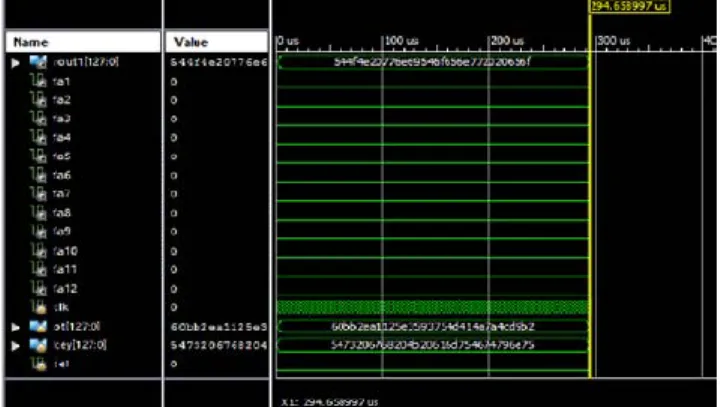
Figure 4: shows the simulation result of round1 operation.
Figure 4:Simulation result of Round1 operation
This result shows the round1 operation, in which Sub byte, Shift rows, Mix column and add round key operations are performed. Similarly, all 10 rounds are performed in AES encryption and decryption. Fa1 and
Fa2 shows the status of fault in fig.4. If Fa=0, then no fault and if Fa=1, then fault is present. Fig.5 and Fig.6 shows simulation result of encryption and decryption operation.
Figure 5:Simulation result of Encryption
Figure 6:Simulation result of Decryption.
IX.
Conclusion
In communication system information security is most important. AES algorithm, can resist any kinds of password attacks with a strong practicability and reliability. The AES algorithm can be efficiently implemented by using FPGA platform. During implementation of AES some natural and malicious
faults are injected. It is necessary to resist those faults for better performance of AES algorithm.
In fault detection scheme critical path of the AES round operation is divided into two halves and a pipeline register is inserted in between them and normal encryption and re-encryption operations are performed. Simulation results show the round1, encryption and decryption operations. During encryption and decryption
Global Journal of Computer Science and Technology Volume XVII Issue II Version I
27 Year 2017 ( ) H
High Speed AES Algorithm to Detect Fault Injection Attacks and Implementation using FPGA
process faults are injected and the flag error shows the status of fault. This scheme can be implemented using Xilinx and Spartan-6 FPGA platform. Compared to some previous works, this method achieves 99.99% fault coverage. In future work text input, can be replaced with audio or video input.
References Références Referencias
1. Hassen Mestiri, FatmaKahri, Belgacem Bouallegue, Mohsen Machhout, “A high speed AES design resistant to fault injection attacks”, Microprocessors and Microsystems journal,2016 Elsevier, pp.47-55. 2. J. Chu, M. Benaissa, “Error detecting AES using
polynomial residue number systems”, Microproce-ssor and Microsystem journal” , 37(2) (2012), pp. 228–234.
3. J. Rajendran, H. Borad, S. Mantravadi, R. Karri, “SLICED: Slide-based concurrent error detection technique for symmetric block ciphers,” IEEE International Symposium on Hardware-Oriented Security and Trust, 2010, pp. 70-75.
4. M. Mozaffari - Kermani, A. Reyhani - Masoleh, “Concurrent structure independent fault detection schemes for the advanced encryption standard”,
IEEE Transaction on computers. 59 (2010), pp.608– 622.
5. L. Lan, “The AES encryption and decryption realization based on FPGA,” Seventh International Conference on Computational Intelligence and Security (CIS 2011), 2011, pp. 603-607.
6. H. Mestiri, N. Benhadjyoussef, M. Machhout,
R. Tourki, “High performance and reliable fault detection scheme for the advanced encryption standard”, International Rev. on Com. Soft. (IRECOS)8(3),2013,pp.730–748.
A. Moh'd, Y. Jararweh and L. Tawalbeh, “AES-512: 512-bit Advanced Encryption Standard algorithm design and evaluation,” 7th International Conference on Information Assurance and Security (IAS 2011),
2011, pp. 292-297.
7. Hoang Trang, Nguyen Van Loi “An efficient FPGA implementation of the Advanced Encryption Standard algorithm” IEEE Symposium on Industrial Electronics & Applications (ISIEA), 2012, pp. 696-699.
8. H. Mestiri, N. Benhadjyoussef, M. Machhout, R. Tourki, “A Robust fault detection scheme for the advance decryption standard”, International journal of Computer Network and Information Security(IJCNIS),2013,pp.49–55.
9. M. Joye, P. Manet, and J.B. Rigaud, “Strengthening hardware AES implementations against fault attacks,” IET Information Security, pp. 106-110, Sept, 2007.
10. Guo, D. Mukhopadhyay, and R. Karri, “Provably Secure Concurrent Error Detection Against
Differential Fault Analysis,” IACR Cryptology ePrint Archive, Available from:eprint.iacr.org/2012/552.pdf, 2012.
11. William Stallings, “Cryptography and Nework Security”, Third Edition, Pearson Education, 2003.
Global Journal of Computer Science and Technology Volume XVII Issue II Version I
28 Year 2017 ( ) H
![Figure 1: General Structure of AES [1]](https://thumb-us.123doks.com/thumbv2/123dok_us/10972808.2985339/3.893.290.625.302.695/figure-general-structure-of-aes.webp)
![Figure 3: AES round with fault detection scheme [1]](https://thumb-us.123doks.com/thumbv2/123dok_us/10972808.2985339/4.893.247.656.611.881/figure-aes-round-fault-detection-scheme.webp)