University of Bradford eThesis
This thesis is hosted in Bradford Scholars – The University of Bradford Open Access
repository. Visit the repository for full metadata or to contact the repository team
© University of Bradford. This work is licenced for reuse under a
Creative Commons
Licence
.
Modelling and Analysis of Resource
Management Schemes in Wireless
Networks
Zaid Ahmed Said Zabanoot
Ph.D
1
Modelling and Analysis of Resource
Management Schemes in Wireless
Networks
Analytical Models and Performance Evaluation of Handoff
Schemes and Resource Re-Allocation in Homogeneous and
Heterogeneous Wireless Cellular Networks
Zaid Ahmed Said Zabanoot
Submitted for the degree of Doctor of Philosophy
School of Computing, Informatics and Media
University of Bradford
I
Abstract
Over recent years, wireless communication systems have been experiencing a dramatic and continuous growth in the number of subscribers, thus placing extra demands on system capacity. At the same time, keeping Quality of Service (QoS) at an acceptable level is a critical concern and a challenge to the wireless network designer. In this sense, performance analysis must be the first step in designing or improving a network. Thus, powerful mathematical tools for analysing most of the performance metrics in the network are required. A good modelling and analysis of the wireless cellular networks will lead to a high level of QoS.
In this thesis, different analytical models of various handoff schemes and resource re-allocation in homogeneous and heterogeneous wireless cellular networks are developed and investigated. The sustained increase in users and the request for advanced services are some of the key motivations for considering the designing of Hierarchical Cellular Networks (HCN). In this type of system, calls can be blocked in a microcell flow over to an overlay macrocell. Microcells in the HCN can be replaced by WLANs as this can provide high bandwidth and its users have limited mobility features. Efficient sharing of resources between wireless cellular networks and WLANs will improve the capacity as well as QoS metrics.
This thesis first presents an analytical model for priority handoff mechanisms, where new calls and handoff calls are captured by two different traffic arrival processes, respectively. Using this analytical model, the optimised number of channels assigned to
II
handover calls, with the aim of minimising the drop probability under given network scenarios, has been investigated. Also, an analytical model of a network containing two cells has been developed to measure the different performance parameters for each of the cells in the network, as well as altogether as one network system. Secondly, a new solution is proposed to manage the bandwidth and re-allocate it in a proper way to maintain the QoS for all types of calls. Thirdly, performance models for microcells and macrocells in hierarchical cellular networks have been developed by using a combination of different handoff schemes. Finally, the microcell in HCN is replaced by WLANs and a prioritised vertical handoff scheme in an integrated UMTS/WLAN network has been developed. Simulation experiments have been conducted to validate the accuracy of these analytical models. The models have then been used to investigate the performance of the networks under different scenarios.
Keywords: Analytical Models, Handoff Schemes, Resource Re-Allocation, Performance Evaluation, Hierarchical Cellular Networks, Integrated Wireless Networks.
III
Table of Contents
Abstract...I
Table of Contents...III
List of Tables...VIII
List of Figures...IX
List of Abbreviations...XII
List of Symbols...XV
Acknowledgements...XVIII
List of Publications...XIX
1 Introduction...1
1.1 Background and Motivation ... 1
1.2 Aims and Objectives ... 4
1.3 Contributions ... 5
1.4 Thesis Outline ... 7
2 Background Research...9
2.1 Wireless Cellular Networks ... 9
2.2 Multiple Access Methods ... 13
2.3 Handoff ... 14
IV
2.3.2 Vertical Handoff... 15
2.3.3 Hard Handoff ... 16
2.3.4 Soft Handoff ... 17
2.4 Channel Allocation Schemes ... 17
2.4.1 Channel Reservation Schemes (CRS) ... 19
2.4.2 Handoff Queuing Schemes (HQS) ... 20
2.4.3 Channel Transferred Handoff Schemes (CTHS) ... 21
2.4.4 Sub-Rating Schemes (SRS) ... 21
2.4.5 Genetic Handoff Scheme (GHS) ... 22
2.4.6 Hybrid Handoff Schemes (HHS) ... 22
2.5 Hierarchical Wireless Cellular Network ... 23
2.6 Hierarchical Cellular/WLAN Overlay Architecture ... 24
2.7 Wireless Network Mobility Management Methods ... 24
2.7.1 Mobility Management for 1G Wireless Networks ... 25
2.7.2 Mobility Management for 2G Networks ... 25
2.7.3 Mobility Management for 2.5G Networks ... 27
2.7.4 Mobility Management for 3G Networks ... 28
2.7.5 Mobility Management Scheme Comparison ... 30
2.7.6 Mobility Management in 4G Networks ... 31
3 Performance Modelling of Handoff Mechanisms in Single and Two
Cells Wireless Cellular Network...32
3.1 Introduction ... 32
V
3.2.1 Analytical Model ... 34
3.2.2 Validation of the Model ... 37
3.2.3 Performance Analysis ... 40
3.3 Performance Model of Handoff Mechanisms in Two-Cells ... 41
3.3.1 Network System Model ... 41
3.3.2 Validation of the Model ... 45
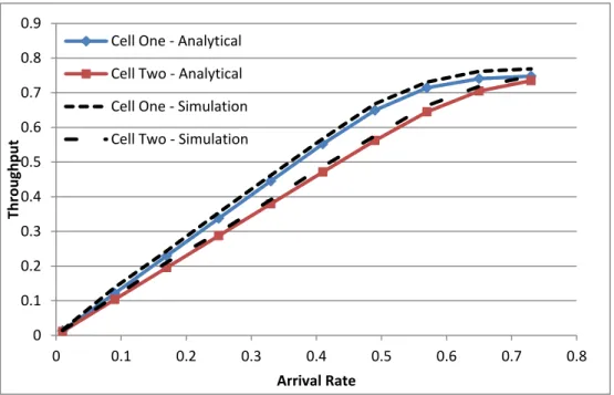
3.3.3 Performance Analysis ... 48
3.4 Summary ... 50
4 Bandwidth Re-Allocation Management in 3G Wireless Cellular
Networks...52
4.1 Introduction ... 52
4.2 Channel Allocation Schemes ... 54
4.3 Proposed Architecture and Bandwidth Management Scheme ... 55
4.3.1 Architecture ... 55
4.3.2 Proposed Bandwidth Management Scheme in Three Scenarios ... 57
4.4 Proposed Algorithm... 61
4.5 Analytical Evaluation ... 61
4.5.1 Bandwidth Management for Existing Calls ... 62
4.5.2 Bandwidth Management when Higher Priority Handoff Call Arrive ... 63
4.5.3 Bandwidth Management when Lower Priority Handoff Call Arrive ... 63
4.6 Performance Evaluation, Simulation & Results ... 64
VI
4.6.2 Performance Evaluation for Bandwidth Management when Higher Priority
Handoff Calls Arrive ... 67
4.6.3 Performance Evaluation when Lower Priority Handoff Calls Arrive ... 71
4.7 Summary ... 75
5 Performance Design and Analysis of Handoff in Hierarchical
Wireless Networks...77
5.1 Introduction ... 77
5.2 System Model and Performance Analysis ... 81
5.2.1 System Model ... 81
5.2.2 Performance Analysis of the Microcell ... 83
5.2.3 Performance Analysis of Macrocell Layer ... 87
5.2.4 The Degradation Ratio in the Microcell... 89
5.3 Numerical Results, Validation and Discussion ... 90
5.4 Summary ... 96
6 Modelling of Prioritise Vertical Handoff Scheme in Integrated
UMTS/WLANs...97
6.1 Introduction ... 97
6.2 Model Description ... 100
6.3 Performance Analysis ... 102
6.3.1 Flow diagram ... 102
6.3.2 Handoff Arrival Rate Estimation ... 106
6.3.3 Channel Holding Time ... 106
VII
6.3.5 Performance measures ... 109
6.4 Validation of the Model... 111
6.5 Numerical Results and Discussion ... 112
6.6 Summary ... 116
7 Conclusions and Future Directions...117
7.1 Summary of results ... 117
7.2 Direction of Future Work ... 120
VIII
List of Tables
Table 2-1: Handoff Types Classification ... 14
Table 2-2: Mobility Management Scheme Comparisons ... 30
Table 3-1: Simulation Parameters for Single Cell ... 38
Table 3-2: Results of the Analytical Performance Model and the Simulation of Handoff Dropping Probability and New calls Blocking Probability... 39
Table 3-3: Simualtion Parameters for Two Cells ... 45
Table 4-1: Bandwidth Table... 57
Table 4-2: Bandwidth Management for Existing Calls... 65
Table 4-3: Bandwidth table for High Priority calls ... 67
Table 4-4: Banwidth table for Lower Priority calls ... 72
Table 5-1: Proposed Scheme for the Microcell... 83
IX
List of Figures
Figure 2.1: Simple PLMN ... 11
Figure 2.2: Hard Handoff between MT and BSs ... 16
Figure 2.3: Reference Architecture of a 2G Network ... 26
Figure 2.4: UMTS Circuit Switched Mobility Management States ... 29
Figure 2.5: UMTS Packet Switched Mobility Management States ... 29
Figure 3.1: Two Classes System Model ... 34
Figure 3.2: State Transition Diagram ... 34
Figure 3.3: Validation of the Analytical Performance Model of New Calls Blocking Probability by a Simulation. ... 38
Figure 3.4: Validation of the Analytical Performance Model of Handoff Dropping Probability by a Simulation ... 39
Figure 3.5: Optimisation of Handover guard channels (g) ... 40
Figure 3.6: Two cells queuing system model... 41
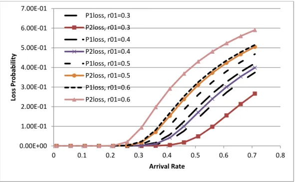
Figure 3.7: Loss Probability for each Queue ... 46
Figure 3.8: Mean Total Delay or Mean Response Time for each Queue ... 47
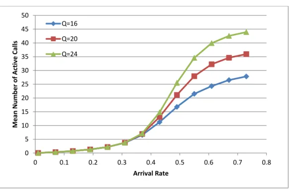
Figure 3.9: Mean Number of Active calls or Mean Queue Length for each Queue ... 47
Figure 3.10: Throughput for each Queue ... 48
Figure 3.11: Blocking Probability of a Two-cells Network ... 49
X
Figure 3.13 : Loss Probability in the network by increasing the handoff rate between the
cells ... 50
Figure 4.1: Cellular Network Architecture ... 56
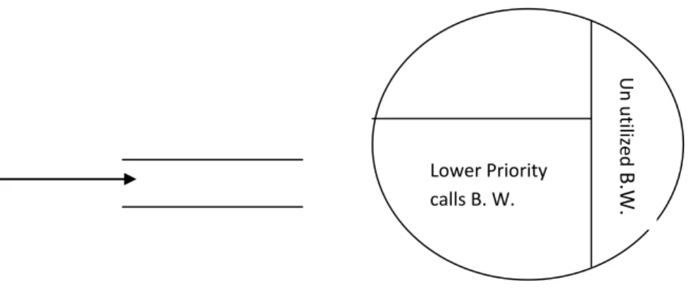
Figure 4.2: bandwidth in Cell with no handoff calls in Queue ... 59
Figure 4.3: Bandwidth in Cell with handoff Calls in Queue... 60
Figure 4.4: Bandwidth for existing calls ... 66
Figure 4.5: Total Bandwidth for all calls ... 66
Figure 4.6: Allocation within the cell when Higher Priority Handoff call Arrived ... 69
Figure 4.7: Allocation from neighbouring cell ... 69
Figure 4.8: Bandwidth Management after Node left ... 70
Figure 4.9: Bandwidth Management when channels are requested from neighbour ... 70
Figure 4.10: Lower Priority Handoff calls arrived ... 73
Figure 4.11: Bandwidth Borrowed from neighbour ... 73
Figure 4.12: When Higher Priority Handoff Call arrived ... 74
Figure 4.13: Minimum Bandwidth Allocation for Lower Priority Handoff call (Worst Case Scenario) ... 74
Figure 5.1: State Transition Diagram of the Microcell ... 85
Figure 5.2: State Transition Diagram of the Macrocell ... 87
Figure 5.3: Blocking Probability of Slow New Call ... 92
Figure 5.4: Dropping Probability of Slow Handoff Call... 93
Figure 5.5: Blocking Probability of Fast New Call ... 94
XI
Figure 5.7: Degradation Ratio of Voice Quality for Slow New and Handoff Calls in the
Microcell ... 95
Figure 6.1: Integrated UMTS/WLANs Network Model ... 101
Figure 6.2: Flow Diagram of the Integrated UMTS/WLANs ... 103
Figure 6.3 : Dropping Probability of UMTS New Call (Analytical and Simulation) ... 111
Figure 6.4: Dropping Probability of UMTS Horizontal Handoff Call (Analytical and Simulation) ... 112
Figure 6.5: Dropping Probability of UMTS New Call with effect of K and C ... 113
Figure 6.6: Dropping Probability of UMTS Horizontal Handoff Call with effect of K and C ... 113
Figure 6.7: Dropping Probability of UMTS New Call with Effect of WLANs coverage Rate (g) ... 114
Figure 6.8: Dropping Probability of UMTS Horizontal Handoff Call with Effect of WLANs coverage Rate (g) ... 114
XII
List of Abbreviations
1G First Generation (Mobile Network) 2G Second Generation (Mobile Network) 3G Third Generation (Mobile Network) 4G Fourth Generation (Mobile Network) AMPS Advanced Mobile Phone System AUC Authentication Center
BS Base Station
CAC Call Admission Control CAS Channel Allocation Schemes
CBHS Channel Borrowing Handoff Schemes CBS Call Bounding Scheme
CCHS Channel Carrying Handoff Schemes CDMA Code Division Multiple Access CRS Channel Reservation Schemes CRT Cell Residence Time
CTHS Channel Transferred Handoff Schemes D-AMPS Digital-Advanced Mobile Phone System DCA Dynamic Channel Allocation
DCRS Dynamic Channel Reservation Schemes DHQS Dynamic Handoff Queuing Schemes
XIII
DVH Downward Vertical Handoff
EDGE Enhanced Data Rates for Global Evolution EIR Equipment Identification Register
FCA Fixed Channel Allocation
FDMA Frequency Division Multiple Access GGSN Gateway GPRS Support Node GHS Genetic Handoff Scheme GMM GPRS Mobility Management GPRS General Packet Radio Service
GSM Global System for Mobile Communications HCA Hybrid Channel Allocation
HCN Hierarchical Cellular Network HCS Hierarchical Cellular Structure HH Horizontal Handoff
HHS Hybrid Handoff Schemes HLR Home Location Register HQS Handoff Queuing Schemes
HSCSD High Speed Circuit Switched Data IP Internet Protocol
MSC Mobile Switching Service Center MT Mobile Terminal
MTSO Mobile Telephone Switching Office NAMPS Narrow band AMPS
XIV
NMT Nordic Mobile Telephone NPS Non-Prioritized Scheme
PCS Personal Communication Systems PLMN Public Land Mobile Network
PSTN Public Switched Telephone Network QoS Quality of Service
RAN Radio Access Network
SCRS Static Channel Reservation Schemes SGSN Serving GPRS Support Node
SHQS Static Handoff Queuing Schemes SHT Session Holding Time
SRS Sub-Rating Schemes
TACS Total Access Communication System TACS Total Access Communication System TDMA Time Division Multiple Access UHF Ultra-High-Frequency
UMTS Universal Mobile Telecommunication System UVH Upward Vertical Handoff
VH Vertical Handoff
VLR Visitor Location Register WLAN Wireless Local Area Network
XV
List of Symbols
Number of Guard Channel for Handoff Calls New Call Arrival Rate
Handoff Call Arrival Rate
Service Rate for Ongoing Call (New or Handoff) Service Rate of Handoff Calls
( ) Blocking Probability of New Calls
( ) Dropping Probability of Handoff Calls
[ ] Mean Number of Active Calls in the Network (2 cells)
Blocking (loss) Probability of the network (2 cells)
Total Network Throughput (2 cells)
[ ] Mean Response Time (Mean Total Delay) of the Network (2 Cells)
Total Bandwidth Allocated to Calls
Total Bandwidth Utilized by Calls
Total Bandwidth not Utilized
Total Number of Active Lower Priority Calls
Bandwidth for Active Lower Priority Call
Total Bandwidth Utilized by Active Lower Priority Calls
Bandwidth Requested by Higher Priority Handoff Call
XVI
Total Bandwidth of Active Lower Priority Calls Calculated after Minimum
Bandwidth Borrowed from Neighboring Cell
Bandwidth Requested by Lower Priority Handoff Call
Slow New Call Arrival Rate to Microcell Fast New Calls Arrival Rate to Macrocell
Slow Handoff Call Arrival Rate to Microcell Fats Handoff Calls Arrival Rate to Macrocell
Mean Arrival Rate of Overflowed Slow New Call from Microcell
Mean Arrival Rate of Overflowed Slow Handoff Call from Microcell
( ) Mean Channel Holding Time in the Microcell
( ) Mean Dwell Time in the Microcell
Blocking Probability of Slow New Calls in the Microcell Blocking Probability of Slow Handoff Calls in the Microcell Blocking Probabilities of Fast New Calls in the Macrocell Dropping Probability of Fast Handoff Call in the Macrocell
Blocking Probabilities of Overflowed Slow New Calls in the Macrocell Dropping Probability of Overflowed Slow Handoff Call in the Macrocell Total Slow New Call Blocking Probability Including Microcell and
Macrocell
Total Slow Handoff Call Dropping Probability Including Microcell and
Macrocell
[ ] Expected Number of Busy Channels in the Microcell
XVII
[ ] Mean Degradation Ratio of Voice Quality for Microcell Slow New Calls
[ ] Mean Degradation Ratio of Voice Quality for Microcell Slow Handoff Calls
Arrival Rate of New Calls in the UMTS
Arrival Rate of Horizontal Handoff Calls in the UMTS Arrival Rate of Vertical Handoff Calls in the UMTS
Arrival Rate of New Calls in the WLANs
Arrival Rate of Vertical Handoff Calls to the WLANs
[ ] Mean Channel Holding Time for New Calls of UMTS Users
[ ] Mean Channel Holding Time for Back Vertical Handoff Calls of UMTS
Users
[ ] Mean Channel Holding Time for Horizontal Handoff Calls of UMTS Users
[ ] Channel Occupancy Time for WLANs Users
[ ] Channel Occupancy Time for Vertical Handoff UMTS Users in WLANs
( ) Steady State Probability of New, Horizontal Handoff and Back Vertical Handoff Calls from the UMTS Users in the UMTS Cell
( ) Steady State Probability of Calls of WLANs Users and the Number of Vertical Handoff Calls of UMTS Users in the WLANs
Dropping Probability of New Calls in UMTS and WLANs for UMTS
users
Dropping Probability of Horizontal Handoff Calls in UMTS and WLANs
XVIII
Acknowledgements
I thank God for giving me the opportunity and strength to undertake and complete this research program.
Working on PhD research is both a painful and enjoyable experience. It is like climbing a high mountain that you would not be able to reach the top of without having the help and experience of others, and people who believe in you that you can get there. I have now found myself at the top enjoying the feeling of relief, and I would like to give many, many thanks to all the people who have helped me during my research.
First of all, I would like to express my deep gratitude to my supervisor, Dr. Geyong Min for his invaluable guidance and continuous understanding, support and encouragement throughout my research, as well as the valuable sharing of thoughts during these years. His extensive knowledge, strong analytical skills, and commitment to excellence in research and teaching are truly treasures to his students. Without his help I would not have completed my PhD study and this thesis would not exist.
Thanks go also to my second supervisor Prof. Mike Woodward for his ideas and guidance at the beginning of my research.
I am forever indebted to my parents for their understanding, endless patience and encouragement whenever it is needed. They always let me know that they are proud of me, which motivates me to work harder and do my best.
Last but not least, thanks to all my friends in Oman and those I have met in Bradford for their help.
XIX
List of Publications
Z. Zabanoot, G. Min, M. E. Woodward, Performance modelling and analysis of handover mechanisms in wireless cellular networks, Proc. Int. Conference on Computer & Communication Engineering (ICCCE '06), Malaysia, May 9-11, pp. 907-910, 2006. Z. Zabanoot, G. Min, Mike Woodward, A Fair Solution for Bandwidth Re-Allocation Management in 3G Wireless Cellular Networks, Proc. Int. Conference on Information and Communication Technology and Systems (ICTS ‘09), Indonesia, August 4-6, pp. 1-8, 2009.
Z. Zabanoot, G. Min, Performance Design and Analysis of Handoff in Hierarchical Wireless Networks, Accepted at: The Second International Workshop on Wireless Networks and Multimedia (WNM-2011), 16-18 November 2011, Changsha, China. Z. Zabanoot, G. Min, Modeling of Prioritised Vertical Handoff Scheme in Integrated UMTS-WLANs, ready to submit to: Wireless Communications and Networking Conference (WCNC 2012).
1
Chapter 1
Introduction
1.1
Background and Motivation
Cellular network technology is one of the fastest growing forms of mobile communications today. The bounds of an existing communication network infrastructure have been extended by cellular technology via connecting mobile units to public networks operated by the local exchange or long distance carriers, in order to make special features and functions specific to both cellular and public networks available to all users. Global standards have been developed to provide voice and data services anytime and anywhere regardless of user mobility, while satisfying their diverse Quality of Service (QoS) requirements. The frequency spectrum allocated for cellular communications is very limited. The success of today's cellular network is mainly due to the frequency reuse concept. This is why the coverage area is divided into cells, each of which is served by a base station (BS). Each BS (or cell) is assigned a group of radio channels according to the transmission power constraints and availability of spectrum. A channel can be a frequency, a time slot or code sequence. To avoid radio co-channel interference, the group of channels assigned to one cell must be different from the group of channels assigned to its neighboring cells. However, the same group of channels can be assigned to
2
the two cells that are far enough apart such that the radio co-channel interference between them is within a tolerable limit.
As it is very important to satisfy the QoS requirements of the user, an efficient resource management is required during handoff when the mobile terminal (MT) moves from one cell to another. The problem of maintaining service continuity for users’ applications during handoffs has been intensified with the use of better handoff schemes, or increasing the number of microcells and integration with other technologies in cellular networks. Call admission control (CAC) schemes have been developed to manage scarce radio resources to maximise network utilisation by selectively limiting the number of admitted calls. Two important QoS measures used when evaluating performance of call admission control schemes are the probabilities of call blocking and call dropping. Call blocking occurs when a cellular network is unable to assign network resources to enable a call initiated in a cell, whereas call dropping occurs when a cellular network is unable to assign network resources to enable a call handed off from a neighbouring cell. A higher priority is normally assigned to handoff calls over the new ones to minimise the probability of call dropping, since dropping an on-going call is generally more objectionable to a user than blocking a new call request. However, reducing dropping probabilities for handoff calls, as they have higher priority, increases the probability of blocking for calls with relatively lower priorities resulting in a tradeoff between both types of calls. Therefore, the goal is to sustain a balance between calls of different priorities while satisfying the respective QoS requirements.
Call admission control has been intensively studied in the past [1] and many priority-based CAC schemes have been proposed [2-17]. Call admission control schemes
3
are analysed using Markov chain models. Markov chain models have been developed to evaluate performance analytically in cellular networks. Calls arriving to a particular cell are grouped into QoS classes or call types, such as new and handoff, based on their first appearance in the corresponding cell. Channel occupancy times for each group are measured from the call starting time, until the occupied channel in the respective cell is discarded due to call termination or handoff. However, call holding times are measured from the call starting time until call termination, regardless of occupying a channel in the same cell or not. The characteristics of various types of channel occupancy times need to be analysed to provide sufficiently representative channel occupancy time statistics, not only when developing analytical models, but also for feeding simulations with realistic traffic statistics to obtain network performance metrics.
As the number of subscribers to wireless networks is increasing dramatically, there has been much research work carried out to improve the capacity of these networks by using hierarchical cellular networks (HCN) [88, 89]. In these networks, the cells are grouped into two different layers depending on their sizes; microcell in one layer and macrocell in another layer. Depending on the CAC schemes used to assign channels for new and handoff calls, each layer can receive a type of call class, and calls which are blocked at one layer can overflow to the other layer. The microcell can be replaced by WLANs and it can be integrated with the overlay macrocell.
Most of current research on the integration of wireless cellular networking and WLAN focuses on relatively high-level issues such as the integration architecture [111]. The system is often studied from the perspectives of access control, mobility management, security and billing and so on. Another research focus of cellular/WLAN
4
integration is the issue of Radio Access Network (RAN) selection and handover decision [112]. Here, the objective is to use the handoff schemes in a way that improves the network performance and decreases the dropping probabilities of new and horizontal handoff calls of the UMTS users by allowing them to vertically handoff to the WLANs. Handover makes mobility possible, but also makes the mobile-level topology of cellular/WLAN integrated systems challenging due to user mobility in the study of such systems.
1.2
Aims and Objectives
The research work in this thesis is mainly aimed towards studying different mechanisms of handoff under different network scenarios with the aim of decreasing the dropping probability of handoff calls, whilst at the same time keeping the blocking probability of new calls to a minimum. The main objectives of the research are outlined as follows:
To develop an analytical model for priority handover mechanisms and optimise the number of channels assigned to handover calls, with the aim of minimising the drop probability under given network scenarios.
To develop and provide a performance model for a two-cell model as one network system, and measure the different performance parameters for each of the cells in the network altogether as one network system.
To develop a solution for re-allocation of the unutilised bandwidth to be used fairly by all nodes who request a bandwidth.
To develop a new performance model for Macro/ Micro cells network which supports fast and slow mobility users.
5
To propose a performance model for prioritising a vertical handoff scheme in integrated UMTS/WLAN network.
1.3
Contributions
The original contributions of this thesis are outlined below:
An analytical model for priority handover mechanisms whereby new calls and handover calls are captured by two different traffic arrival processes respectively will be developed. The analytical performance model has been validated by simulation experiments. Using the blocking probability of the new calls and the drop probability for handover calls derived from the analytical model, the optimised number of channels assigned to handover calls was calculated with the aim of minimising the drop probability under given network scenarios. Also, a performance model for a two-cell network has been developed and the different performance parameters have been measured for each of the cells in the network and all together as one network system.
A new solution model is proposed to manage the bandwidth. A bandwidth, which is not utilised by fewer mobile nodes, will be re-allocated to the needy ones. In order to maintain the QoS for the higher priority handover call (multimedia call), the focus here is to allocate the required bandwidth to this call and maintain constancy during its connection life time. For the lower priority handover call (data call) at least the minimum bandwidth will be allocated in the worst-case scenario. The unutilised bandwidth will be distributed fairly among active lower
6
priority nodes, and will be utilised later by either handover calls or incoming local calls. With this method, maximum bandwidth in the cell will be reached, and it will remain available whenever a new call, either handover or locally generated, comes in; thus, the wastage of network resources can be avoided. The dropping probability of handover calls will be reduced to a minimum and the blocking probability of newly generated calls will be maintained at a minimum through this method.
Performance models for a two layer microcells/ macrocell Hierarchical Cellular Network will be developed by using 1-D and 2-D markov process for microcell and macrocell, respectively. In this proposed CAC, the HCN system supports both fast and slow mobility users. The macrocells handle the fast-mobility users while the microcells serve the slow-mobility users. In the microcells, a combination of sub-rating, call bounding and handoff queuing schemes is used, while in the macrocell the call bounding scheme is used. The effect of sub-rating in the microcell on the voice quality is also studied.
A new performance model will be developed to prioritise the vertical handoff scheme in integrated UMTS/WLAN networks. In this model, the call residence times are modelled by general distribution to adapt the flexible mobility environments. The new originated and horizontal handoff call of UMTS users that are blocked in the UMTS-only coverage, can attempt a vertical handoff to the underlying WLANs. In the WLANs these call are given more priority than the WLANs users’ call by reserving some channels for them, plus they can share the
7
rest of the channels with the WLANs users. The channel occupancy times and the blocking and dropping probabilities have been derived and calculated.
1.4
Thesis Outline
The rest of the thesis is organised as follows:
Chapter 2 presents the background to the research and related work for handoff mechanisms in single and two layer networks. It discusses the different types of handoff and channel allocation schemes. Also, it presents an overview of the integration between cellular networks and wireless local area networks.
Chapter 3 presents a performance model to optimise the number of channels assigned to handoff calls with the aim of minimising the drop probability under given network scenarios, and to keep the new call blocking probability at a minimum. Also, this chapter includes developing a performance model for a two-cell network and studies its performance parameters.
Chapter 4 proposes a new solution to manage the bandwidth in 3G network and re-allocate the unutilised bandwidth in better way to be used by all types of calls and not be wasted. The multimedia calls are given higher priority and they are assigned more bandwidth to keep it constant during their lifetime. The data calls are lower priority and are given at least the minimum bandwidth in the worst case scenario.
Chapter 5 develops a performance model for a two layer microcells/ macrocell Hierarchical Cellular Network to enhance the performance of the network. The dropping
8
and blocking probability of slow and fast mobility user calls is calculated. The blocked slow calls in the microcell are allowed to overflow to the overlay macrocell to minimise the dropping and blocking probabilities. The number of microcells has been increased to see the effect on the network performance. The voice degradation because of using sub-rating in the microcell has also studied.
Chapter 6 develops a performance model for an integrated UMTS/ WLAN network. The newly originated and horizontal handoff call of UMTS users that are blocked in the UMTS-only coverage, can attempt a vertical handoff to the underlying WLANs, and they are given more priority in the WLANs than the WLANs users. The size of the WLANs has been varied to see the effect on the network performance.
9
Chapter 2
Background Research
This chapter provides an overview of some background knowledge related to the work in this thesis. In Section 2.1, an introduction to wireless cellular networks will be given and the basics will be explained, including how it works and the importance of mobility. In Section 2.2, an overview will be presented of multiple access, briefly explaining the basic three multiple access methods. The horizontal and vertical handoff will be explained in Section 2.3. Also, another classification of handoff- hard and soft- will be explained in the same Section. In Section 2.4, the different channel allocation schemes that have been used in wireless cellular networks will be explained. Section 2.5 will highlight the importance of hierarchical wireless cellular networks to improve performance, and the integration of UMTS with WLANs will be briefly discussed in Section 2.6. Finally, the wireless networks mobility management methods in the different generations will be discuss in Section 2.7.
2.1
Wireless Cellular Networks
Telephone service subscribers are a demanding group of customers. Ubiquitous access, reliability, availability, scalability and ease of use are expected attributes of telephone
10
networks. The continuous evolution of the telephone network satisfies these requirements by varying degrees. Network technology, cost of service and infrastructure establishment, are the major impediments to complete customer satisfaction.
Wireless mobile telephone networks or public land mobile networks (PLMNs) leverage the services provided by the public switched telephone network (PSTN). PLMNs use the PSTN as a backbone. PLMNs consist of network elements that provide the infrastructure for wireless access, mobility management and external network gateways [113, 114].
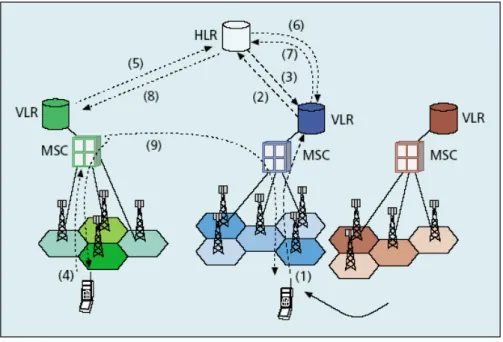
A simple PLMN consists of base stations, mobile switching service centers (MSC), Home Location Register (HLR), Visitor Location Registers (VLR), Authentication Center (AUC) and an Equipment Identification Register (EIR), as shown in Figure 2.1.
The base stations provide network access via a radio interface for mobile subscribers. The MSC manages base stations; consults PLMN databases to establish subscriber access rights; routes mobile traffic, and serves as a gateway to external networks. The HLR, VLR, AUC and EIR are PLMN databases, which contain subscriber profiles, location, encryption codes and equipment data.
Call establishment and connection maintenance are fundamental services required by all telephone networks. A PSTN call process for two authorised fixed location subscribers consists of call initiation signalling, connection path establishment, alerting the called party, call acceptance and preservation of connection until the end of session signalling is detected. The PSTN uses the fixed location of the subscriber to simplify network functions. A fixed subscriber location simplifies authentication, call establishment and call preservation. Although a PLMN call process must perform the
11
same functions as a PSTN, subscriber mobility significantly complicates network operations.
In order to provide PSTN services, PLMNs must implement mobility management technologies. These technologies enable PLMNs to establish and maintain calls to authorised mobile subscribers. Mobility management uses the HLR, VLRs, MSCs and Base Stations [115]. The AUC and EIR servers verify subscribers and their equipment. Mobility management technologies strongly influence call quality, reliability and availability.
Mobility management is the fundamental technology for the support of seamless accessing to wireless networks and mobile services. Two main aspects need to be considered in mobility management; these are location management (for example
AUC HLR VLR EIR PLMN MSC BTS BTS BTS PSTN Figure 2.1: Simple PLMN
12
addressing, location registration and update, tracking and paging, and so on) and handoff (Handover) management (for example handoff initialisation, resource relocation, connection re-establishing, and so on) [21, 116].
Handoff management is one of the most critical issues that mobility management protocols are concerned with. There are usually two classes of calls: new calls and handoff calls. The new calls are the ones which are just starting within the cell and the handoff calls are calls which are already ongoing, but have moved onto a new cell and need to connect to a new base station. When a new call is originated and attempted in a cell, one of the channels assigned to the base station of the cell is used for communication between the mobile user and the base station if any channel is available for the new call. If all the channels assigned to the base station are in use, the new call attempt is blocked and cleared from the system. When a new call gets a channel, it keeps the channel until it is completed in the cell or the mobile moves out of the cell. When the call is completed in the cell, the channel is released and becomes available to serve another call. When the mobile crosses a cell boundary into an adjacent cell while the call is in progress, the call requires a new base station and channel frequency in order to continue. The procedure of changing channels is called handoff (Handover). If no channel is available in the new cell into which the mobile moves, the handoff call is forced to terminate before completion. Incomplete calls are considered less desirable from the user's viewpoint than the occurrence of blocking of a new call, and they should be kept at a minimum. Since a customer's satisfaction is determined by the rate of call completions and how low the connection delays are, it is in the interest of the service provider to meet these satisfaction measures as much as possible.
13
2.2
Multiple Access Methods
Within a cell covered by a BS, there are multiple MTs that need to communicate with the BS. Those mobile terminals must share the air interface in an orderly manner so that MTs within the cell do not interfere with each other. This sharing of the air interface in an orderly manner is referred to as multiple access. Popular multiple access methods include Frequency Division Multiple Access (FDMA), Time Division Multiple Access (TDMA) and Code Division Multiple Access (CDMA) [23].
Frequency Division Multiple Access (FDMA): With FDMA, different signals are assigned frequency channels, and a channel is a frequency. FDMA is a basic technology in the analog Advanced Mobile Phone System (AMPS). With FDMA, each channel can be assigned to only one user at a time. FDMA is also used in the Total Access Communication System (TACS).
Time Division Multiple Access (TDMA): In TDMA, it makes use of the same frequency spectrum but allows more users on the same band of frequencies by dividing the time into “slots”, and it shares the channel between users by assigning them different time slots. TDMA is utilised by Digital-Advanced Mobile Phone System (D-AMPS) and Global System for Mobile communications (GSM). However, each of these systems implements TDMA in a somewhat different and incompatible way.
Code Division Multiple Access (CDMA): In CDMA, each user is assigned a different pseudorandom binary sequence that modulates the carrier, spreading the spectrum of the waveform and giving each user a unique code pattern. This
14
technology is used in ultra-high-frequency (UHF) cellular telephone systems in the 800 MHz and 1.9 GHz bands.
2.3
Handoff
As mentioned earlier, the process of transferring a call from the current cell to a neighbouring cell is called handoff. Handoffs may be classified based on several factors, like the type of network, the involved network elements or the number of active connections and the type of traffic that the network supports. There are two types of handoff: a horizontal handoff which takes place between points of attachment supporting the same network technology, such as between two neighbouring base stations of a UMTS, or between two Access points of a WLAN. On the other hand, a vertical handoff occurs between points of attachment supporting different network technologies, such as, between a WLAN access point and a UMTS base station. Handoffs can also be classified into hard and soft handoffs [20, 21] depending on which BS is serving the MT in the crucial period during handoff execution when there is a communication between the user in question with more than one BSs.
Table 2-1: Handoff Types Classification
Types Classification
Horizontal Intracell Intercell Soft Hard Vertical Downward Upward
15
2.3.1
Horizontal Handoff
Horizontal handoffs in a cellular network can be broadly classified into intra-cell and inter-cell handoffs. Intra-cell handoffs occur when a user, moving within a cell, changes radio channels in order to minimise inter-channel interference under the same BS [18]. On the other hand, inter-cell handoffs occur when an MT moves into an adjacent cell and, therefore, all the MTs connections should be transferred to the new BS [18].
Horizontal handoff can be classified into four phases [122]: Measurement, Initiation, Decision and Execution. In the measurement phase, different measurements will be carried out by the BS and the MT [122, 123] such as Received Single Strength (RSS), Signal to Interference Ratio (SIR), Bit Error Rate (BER), and distance measure. The initiation phase is in order to decide whether a handoff is needed or not, and if it is needed, to initiate the process. In this phase, the handoff process should be accomplished according to the received signal quality inside a cell, or when the MT is moving along the common boundary of two cells, or between two adjacent cells [24]. The objective of the Decision phase is the selection of a new channel in the cell while taking into account the network load and the available resources. In the Execution phase, the network allows the MT which is communicating with BS to transfer its communication to another channel or transfer to another cell. Authentication, database lookup and network reconfiguration all are done during this phase.
2.3.2
Vertical Handoff
Vertical handoffs can be further distinguished into Downward Vertical Handoffs (DVH) and Upward Vertical Handoffs (UVH). In DVH, the mobile user handoffs to the network
16
that has the higher bandwidth and limited coverage, while in UVH the mobile user transfers its connection to the network with a lower bandwidth and wider coverage [19].
The Vertical Handoff process can be classified into three main phases [124, 125]: System Discovery, Handoff Decision and Handoff Execution. In the system discovery phase, the MTs determine the service available in each network and which network can be used. The networks also show the data rate it can support for each service and the QoS parameters. In the handoff decision phase, based on several parameters, the MT determines the network that it should be connected to. During the handoff execution phase, the connection will be re-routed from the current network to the new network in a seamless manner. Authentication, authorisation, and user’s context information transfer is included in this phase.
2.3.3
Hard Handoff
In hard handoffs, an MT is served by only one BS (or by only one access network in the case of vertical handoff) at a time, as in Figure 2.2. It contacts with the new BS or the new network only after having broken its connection with the serving BS. This is referred to as “break before make” connection.
a. Before Handoff b. After Handoff Figure 2.2: Hard Handoff between MT and BSs
17
Hard handoff is used by systems such as the Global System for Mobile Communications (GSM) and General Packet Radio Service (GPRS), where Time Division Multiple Access (TDMA) and Frequency Division Multiple Access (FDMA) are applied [22].
2.3.4
Soft Handoff
In soft handoff, the MT may be served by more than one BS (or by more than one access network). Soft handoff can be used to extend the time needed to make a handoff decision without any loss of QoS. It refers to a “Make before Break” switching action with no disruption of service. The cellular Code Division Multiple Access (CDMA) systems use soft handoff techniques, due to the fact that in these systems a mobile node may communicate with more than one coded channel, which enables it to communicate with more than one BS [22]. In soft handoff, a conditional decision is made on whether to handoff. Making the handoff and deciding to communicate with only one BS depends on the change in the pilot signal strength from the two or more BSs involved. This happens after it is clear that the signal from one BS is considerably stronger than those from the others. It is normally consists of one BS, but other BSs are added when the signal strength between them and the MT exceeds the predefined add threshold.
2.4
Channel Allocation Schemes
As the handoff process is managed by channel allocation schemes (CAS), the main interest is focused on them. CAS deals with how to assign available channels to the newly
18
generated calls within the cell as well as the handoff calls, because the efficient utilisation of the scarce spectrum for cellular communications is certainly one of the major challenges in cellular system design. The most restraining factor on the overall system capacity in wireless networks is the co-channel interference caused by frequency reuse.
As the demand for mobile wireless service increases, the numbers of channels allocated to a cell and the allocation scheme may become insufficient to support the desirable QoS. The CAS can be broadly classified into Non-Prioritized and Prioritization Schemes [24-26], [28-46]. The Non-Prioritized Scheme (NPS) [26] has been employed by the typical radio technologies proposed for Personal Communication Systems (PCS) which operates on a band of 2 GHz. There is no difference between handoff and newly requested calls in this scheme. As long as there is a channel available in the cell, a new or handoff call request will be served, but the request will be blocked if there are no free channels. The main disadvantage of this scheme is that the forced termination probability is relatively higher than is normally anticipated [26, 27].
As the termination of an ongoing call is more annoying than the blocking of a new call [28, 29], [45, 46], several handoff prioritising schemes have been proposed. The basic concept of all handoff prioritisation approaches is to give handoff requests precedence over new session requests in some way. Handoff prioritisation schemes provide an improvement in performance according to the way that each scheme gives priority to handoff calls. Prioritisation handoff channel allocation schemes can be classified into Channel Reservation, Handoff Queuing, Channel Transferred, Sub-Rating, Genetic and Hybrid.
19
2.4.1
Channel Reservation Schemes (CRS)
In these schemes, a number of channels will be reserved exclusively for handoff requests. Depending on whether the set of reserved channels is fixed or varies, these schemes can be further divided into static and dynamic reservation schemes.
- Static Channel Reservation Schemes (SCRS): These schemes set a fixed threshold to guarantee that a proper bandwidth is allocated for handoff calls. There are two ways to do that: either by using Guard Channel Scheme or Threshold Priority Scheme (also called New Call Bounding Scheme) [32]. In Guard Channel Scheme, a number of channels will be reserved to be used by handoff calls only [31] and the remaining channels are shared between new calls and handoff calls. In the Threshold Priority Scheme, the number of admitted new calls will be limited by a predefined threshold [30].
- Dynamic Channel Reservation Schemes (DCRS): based on the variation in the system parameters, each BS will dynamically change the number of reserved channels for handoff. In these schemes, more new connection requests will be accepted compared to the fixed schemes [17, 33]. Depending on the way that these schemes obtain the required information for the variation in the system parameters, they can be classified into Local and Collaborative [29]. The Local Scheme uses the locally available information in the BS, whereas the Collaborative Scheme uses the information obtained from neighbouring BSs.
20
2.4.2
Handoff Queuing Schemes (HQS)
If the MT is in the handoff area and the destination cell has no free channels, then the MT maintains its connection with the source cell and the handoff request will be placed in a queue. The handoff request will be sent to the BS of the destination cell and if a channel is available before the MT crosses the handoff area, then the channel will be assigned to the MT, or it will be forced to terminate the call. HQS gives more priority to handoff calls being queued [34], but it also allows both new calls and handoff calls to be queued [35]. These schemes can be further classified into static and dynamic schemes.
- Static Handoff Queuing Schemes (SHQS): in these schemes there are two general policies: preemptive and non-preemptive. In Preemptive, when a call arrives at a queue and finds a lower priority call in service, the arriving call preempts the lower priority call from the queue and begins its service [36]. The preempted lower priority call will resume its service at the point at which its service was suspended as soon as there are no higher priority calls remaining in the queue. The Non-Preemptive policy requires a call that begins service to complete its service without interruption.
- Dynamic Handoff Queuing Schemes (DHQS): in these schemes the handoff requests in the queue will be dynamically reordered to reduce the probability of forced termination. This dynamic reorder reflects the dynamics of the user motion such as changes in the user moving speed.
21
2.4.3
Channel Transferred Handoff Schemes (CTHS)
In these schemes, if a handoff call request arrives and there are no available channels, a channel from a neighbouring cell will be transferred. There are two categories to be followed by the handoff call request on selecting the transferred channel; they are Channel Carrying Approach and Channel Borrowing Approach.
- Channel Carrying Handoff Schemes (CCHS): in these schemes the MT is allowed to carry its channel to the destination cell. Here the BS of the new cell will maintain the communication using the old channel [37].
- Channel Borrowing Handoff Schemes (CBHS): in these schemes, the cell that has used all its channels is allowed to borrow free channels from the neighbouring cells to be able to accommodate new calls [38]. The channel can be borrowed by the cell if the borrowed channel does not interfere with existing calls.
2.4.4
Sub-Rating Schemes (SRS)
The main concept of Sub-Rating is that an occupied full-rate channel can be temporarily divided into two channels at half of the original rate; one to serve the existing call and the other to serve the handoff request [39]. The channel Sub-Rating mechanism is only activated when all the channels are occupied on handoff request arrival. When a sub-rated channel is released, it is transformed to its original full-rated channel. The SRS scheme reduces the blocking probabilities and the forced termination probabilities of handoff calls but it introduces degradation into the system [40]. A Wideband class has been considered [41] as it accepts channel sub-rating and narrow band classes which does not accept QoS degradation.
22
2.4.5
Genetic Handoff Scheme (GHS)
These schemes use genetic algorithms to assign the channels using local state-based call admission double-threshold policies [42]. Here, the BS only keeps track of the state of information of a small number of cells and makes decisions based on that. This scheme shows better results than some other schemes, but its main drawback is the time needed to assign channels. The genetic algorithms are adaptive procedures that find solutions to problems by an evolutionary process based on natural selection. It is found that these schemes finds better admission policies compared with other well-known methods of handoff reservation for both one-dimensional and two-dimensional cellular networks. However, the time needed to assign channels for the genetic algorithms scheme is the main drawback of it. It mostly applied for hard optimisation problem with larger search spaces.
2.4.6
Hybrid Handoff Schemes (HHS)
HHS are a combination of channel reservation, handoff queuing, channel transfer, genetic and sub-rating schemes [43 – 46]. The main idea of these schemes is to combine the different prioritisation schemes to further decrease the dropping probabilities or to improve channel utilisation. Either two or more prioritisation schemes have been combined in different studies to enhance the performance. For example, some schemes combined Channel Borrowing, Genetic algorithm and channel Degradation schemes to increase the network efficiency. Also, some other hybrid schemes combined sub-rating with handoff queueing and/or with guard channel scheme. Combination of different
23
schemes leads to decreasing of dropping probability of handoff calls and blocking probability of new call.
2.5
Hierarchical Wireless Cellular Network
In recent years, wireless communication systems are experiencing a dramatic and continuous growth in the number of subscribers, thus placing extra demands on system capacity. At the same time, keeping QoS at an acceptable level is a critical concern and a challenge to the wireless network designer. One trend in cellular networks is to shrink cell size in order to accommodate more mobile users and traffic in a given area. The small-cell system has the advantages of greater spectral reuse and larger capacity than those of large-cell systems. However, such a policy results in the increased number of handoff calls and a corresponding increase in signalling load. With inadequate resources in the network, increased handoff rates can lead to high forced call termination probability.
In order to achieve and maintain high network performance, one network design approach is to use a hierarchical cellular structure (HCS). In this structure, cells of different sizes are organised into different layers to provide high coverage and capacity over a given service area. This structure can effectively reduce the number of handoffs in the wireless system, thus significantly improving the overall system capacity.
There are a number of different approaches proposed for handling calls in HCS. [48, 49] present an approach where a new call or a handover call will be directed to the appropriate layer based on its previous speed. In [49], only handoff overflow from the lower layer to the higher layer is allowed. In [50] mobile subscribers travelling in the lower layer may borrow channels from a pool of channels reserved for handoff calls at the
24
higher layer. [51] has presented a mobility-dependent connection admission control scheme, which was analysed assuming the interrupted Poisson process (IPP), under stationary and non-stationary conditions.
2.6
Hierarchical Cellular/WLAN Overlay Architecture
To utilise many useful methods developed in hierarchical cellular network (HCN) research, micro-cells in HCN are replaced with WLANs. The cellular networks have a widely entrenched infrastructure, which provides almost ubiquitous connectivity and supports user mobility levels, from fast trains and highway vehicles to stationary users in an indoor environment. In contrast, WLANs are usually deployed in hotspot local areas. Thus, the cellular/WLAN interworking results in an overlay structure similar in some ways to hierarchical cellular structure. Both cellular access and WLAN access are available to mobile users within WLAN-coverage areas. The incoming traffic load should be properly shared between the overlay macro-cell and WLAN for QoS enhancement, congestion relief, cost reduction and so on.
2.7
Wireless Network Mobility Management Methods
The generation of numbers to describe categories of wireless networks; each generation resolves the issues encountered by its predecessor and introduces new technologies. The ultimate objective of this evolutionary process is to elevate the performance of a wireless network to that of its wireline counterpart. Ideally, subscriber mobility should not affect quality of service.
25
2.7.1
Mobility Management for 1G Wireless Networks
The first generation technologies were limited capacity analog wireless networks with Frequency Modulation (FM) and Frequency Division Multiple Access (FDMA). First Generation networks provided voice delivery services with in-band signaling. Advanced Mobile Phone Service (AMPS), Narrow band AMPS (NAMPS), Nordic Mobile Telephone (NMT), Total Access Communication System (TACS), C-450 and R-2000 were implementations of First Generation networks.
First Generation networks supported mobile subscriber registration, authentication, paging, conditional roaming and RRM. The Mobile Telephone Switching Office (MTSO) provided all mobility management operations. Radio resource management depended on signal strength measurements from base stations. Networks used hard handoffs and supported voice delivery services only.
2.7.2
Mobility Management for 2G Networks
Second Generation wireless networks introduced digital technologies, which significantly improved performance, capacity and services. Voice delivery services continued to be the focus.
A great debate over architecture hampered the introduction of digital technology in 2G wireless networks. The technology chosen to implement a 2G wireless network affects mobility.
Roaming is extremely limited between networks with different technologies. When a mobile terminal changes BS, it may roam to a cell that corresponds to a new serving VLR. In that case it has to update the information stored in the HLR. Therefore, the
26
terminal initiates an update message (1), which, via the BS and MSC, is forwarded to the current associated VLR. The VLR checks its local records. If the terminal’s Mobile Identification Number (MIN) is already stored there, no further action takes place, since the terminal has not changed location area. Otherwise, the terminal’s MIN is stored locally and a new update message is forwarded to the HLR (2). The HLR in turn authenticates the terminal and replies with a positive registration acknowledgment to the new VLR (3). Additionally, the HLR may send a registration cancellation message to the old VLR, or a periodical mechanism may automatically update the VLR database and remove out-of-date entries [52] (refer to Figure 2.3 below) [52].
In this generation, Radio resource management introduced soft handoffs and defined more handoff scenarios.
27
2.7.3
Mobility Management for 2.5G Networks
Second Generation wireless networks continued to focus primarily on voice delivery services. The demand for data delivery services grew rapidly, and as a result, an interim generation of wireless networks was developed. These new network standards were referred to as 2.5 G and they are High Speed Circuit Switched Data (HSCSD), General Packet Radio Service (GPRS) and IS-95B.
The Serving GPRS Support Node (SGSN) and the Gateway GPRS Support Node (GGSN) are new network elements [53]. The SGSN routes all mobile station packet traffic, performs logical link management, supports the mobile station attach /detach process and authenticates mobile stations. Subscriber profiles and location information is stored in the SGSN’s location register. SGSNs serve a group of cells, a Routing Area, within a location area. The GGSN is a protocol converter and it interfaces the GPRS network to external packet data networks. It transforms GPRS traffic to the packet data format of the external network, and readdresses and routes external packets terminating in the GPRS network to the appropriate SGSN. GPRS Mobility Management (GMM) and Session Management (SM) perform security processes, GPRS Attach / Detach procedures, routing area updates and protocol data packet context activation.
GPRS implements mobility management with Idle, Ready and Standby states. The Idle state indicates that the GPRS network is not aware of the mobile terminal. The Standby state indicates that the GPRS network knows the subscriber and its routing area [117]. The Ready state indicates that the GPRS network knows the subscriber, its cell location and is exchanging packets at will.
28
In this generation, subscriber equipment classification determined service access such as concurrent use of voice and data, switched use of voice and data, and exclusive use of one service. The goal was to minimise handoff disruption for voice services and zero packet loss for data services.
2.7.4
Mobility Management for 3G Networks
Enhanced Data rates for Global Evolution (EDGE) are a convergence technology providing GSM and TDMA operators with a migration path to 3G, Universal Mobile Telephone System (UMTS).
UMTS networks leverage GSM and EDGE networks. The result is a network that delivers high bit rates, circuit & packet switched services, Quality of Service (QOS) and compatibility with previous 2G and 2.5G technologies.
Initial implementations contain discrete circuit switched networks within the UMTS’ core network. The packet switching elements share the same names as their 2.5G predecessors.
Registration, authentication and paging activities are determined by mobility management states. Two different three state models are used for circuit and packet switched mobility management [118-121]. Circuit switched mobility management uses MM-Idle, MM-Connected and MM-Detached states as shown in Figure 2.4. Packet switched mobility management uses PMM-Idle, PMM-Connected and PMM-Detached states as shown in Figure 2.5. The mobility management states are indicators of mobile station location resolution.
29
In 3G, Roaming benefits from all the architectural compatibilities and becomes global. Radio resource management implements a broad range of handoffs and supports most mobility issues.
Figure 2.4: UMTS Circuit Switched Mobility Management States
Figure 2.5: UMTS Packet Switched Mobility Management States
PMM-Connected PMM-Detached PMM-IDLE Packet Signalling Connection Setup
Packet IMSI Attach or
RA Update with Packet Switch Signalling Connection Setup Packet IMSI Detach
or
Packet IMSI Attach Rejection or RA Update Rejection Packet Signalling Connection Release MM-IDLE MM-Connected MM-Detached Call Initiation or Location Update IMSI Detach IMSI Attach or Location Update Call Complete
30
2.7.5
Mobility Management Scheme Comparison
Table 2-2: Mobility Management Scheme Comparisons
Network Type
Mobility Management Radio Resource
Management Registration &
Paging Areas AUC Roaming
Handoff Types
1G AMPS
Single Cell & Proprietary Cell Groups MS Only Simple MIN & ESN Conditional Difficult
Network Controlled, Hard, Intra-MSC,
Inter-MSC IS41
2G GSM
Global Single Cell & Location Areas (LA) MS Only 3 keys A3 Algor. Good between GSM Operators
Network Controlled, MAHO, Hard, Intra- BSC,
Intra-MSC & Inter-MSC
2G NA-TDMA
Single Cell & Location Areas (LA)
IS54, CAVE Conditional
Network Controlled, MAHO, Hard, Intra-MSC &
Inter-MSC IS41 2G 2.5G CDM A One IS95 A & B
Single Cell & zone
MS Only Based on Long Code Masks, CAVE Conditional ANSI 41
Mobile Initiated, Network Controlled, Soft, Hard & HO to Analog
ANSI 41 compliant
2.5G GPRS
Global Single Cell, Location Areas (LA),
Routing Areas (RA)
MS Only 3 keys A3 Algor. Good between GSM Operators, SIM
Network Controlled, MAHO, Hard,
Intra- BSC, Intra-MSC & Inter-MSC
3G UMTS
Global Single Cell, Location Areas (LA),
Routing Areas (RA) & UTRAN Routing Area MS & Network Private Master Key algor. Almost Everywhere SIM
NEHO, MEHO, Hard, Soft, and Softer
Intra- BS, Inter-BS, Intra-MSC, Inter-RNC, Inter-SGSN & Inter-Sys.
31
2.7.6
Mobility Management in 4G Networks
In 4G Networks, mobility is a critical aspect. There are three main issues that should be dealt with independently to accommodate an easy work split. Interactions between these aspects should, however, not be overlooked.
The first issue deals with optimal choice of access technology, or how to be best connected. Given that a user may be offered connectivity from more than one technology at any one time, one has to consider how the terminal and the network choose the technology suitable for the services the user is accessing.
The second issue regards the design of a mobility enabled IP networking architecture, which contains the functionality to deal with mobility between access technologies. This includes fast, seamless handoffs (IP micro-mobility), quality of service (QoS), security and accounting.
The third issue concerns the adaptation of multimedia transmission across 4G networks. Indeed, multimedia will be a main service feature of 4G networks, and changing radio access networks may, in particular, result in drastic changes in the network condition. Thus the framework for multimedia transmission must be adaptive.