R
AILROAD
&
C
O
.
™
TrainController
™
Gold and Silver
Version 8
Users Guide
RAILROAD & CO.
™
TrainController
™
Gold and Silver
Version 8
Users Guide
Contact
:
Freiwald Software
Kreuzberg 16 B
D-85658 Egmating, Germany
e-mail: [email protected]
http://www.freiwald.com
All rights reserved.The content of this manual is furnished for informational use only, it is subject to change without notice. The author assumes no responsibility or liability for any errors or inaccu-racies that may appear in this book.
No part of this publication may be reproduced, stored in a retrieval system, or transmit-ted, in any form or by any means, electronic, mechanical, recording, or otherwise, with-out the prior written permission of the author.
Table of Contents
About this Document ... 13
RAILROAD &CO. TrainController™ Users Guide ... 13
Help Menu... 14
The Editions of TrainController™ ... 14
The Differences between TrainController™ Gold and Silver ... 15
Quick Start - Step 1: Installation and Program Start ... 30
Installation ... 30
Program Start ... 31
Quick Start - Step 2: Controlling a Train ... 34
Preparing a Train for Model Railroad Computer Control ... 34
Controlling a Train ... 38
Quick Start - Step 3: Controlling Turnouts – The Switchboard ... 39
Creating a small switchboard control panel... 39
Preparing a Turnout for Model Railroad Computer Control ... 41
Quick Start - Step 4: Creating Blocks - Tracking Train Positions ... 44
Equipping the layout with feedback sensors... 44
Dividing the layout into Blocks ... 45
Entering the locations of Blocks into the Switchboard ... 45
Assigning Feedback Sensors to Blocks ... 47
Displaying train positions on the Computer Screen ... 51
Simulating Train Movements on the Computer Screen ... 53
Quick Start - Step 5: Controlling Trains Automatically ... 55
Spontaneous Runs ... 55
Adjusting the Stop Location ... 56
Creating a Commuter Train ... 61
AutoTrain™ by Drag and Drop ... 62
Commuter Train with intermediate Stop ... 64
1 Introduction ... 72
Schedule ... 79
Manual Train Control ... 79
Comparison Chart ... 80
1.3 Fundamentals of Use ... 82
The Overall Principle ... 82
User Interface Design ... 83
Window Handling ... 83
Window Customization... 85
Customization of Menus, Tool Bars and Keyboard Accelerators ... 86
File Handling ... 86 Edit Mode ... 87 Printing ... 87 Further Steps ... 88 Switchboards ... 88 Train Windows ... 89
The Visual Dispatcher ... 90
2 The Switchboard ... 92
2.1 Introduction ... 92
2.2 Size and Appearance ... 93
2.3 Drawing the Track Diagram ... 98
Space-Saving Turnouts ... 99
2.4 Connecting the Turnouts ... 100
2.5 Signals and Accessories ... 103
Signals ... 104
Accessories ... 105
Connecting Signals and Accessories ... 105
2.6 Text Labels ... 105
2.7 Self-provided Switchboard Symbols and Images ... 106
Self-provided Symbols ... 106
Images ... 107
2.8 Highlighting occupied track sections ... 108
2.9 Displaying Train Names and Symbols in the Switchboard ... 108
2.10 Using the Computer Keyboard as a Control Panel ... 108
3 Train Control ... 109
3.1 Introduction ... 109
The Train Window ... 109
Train List ... 111
3.2 Engines ... 112
3.3 Throttle and Brake ... 115
3.4 Speedometer and Odometer ... 117
Preparing the decoder ... 118
The simplified Profile ... 118
Advanced Fine Tuning of the Speed Profile ... 120
Measuring with Momentary Track Contacts ... 121
Measuring with Occupancy Sensors ... 122
Trimming the Brake Compensation ... 124
Trimming the Maximum Decoder Speed ... 125
Using a Roller Test Bench ... 127
When do I have to profile my Locomotive? ... 128
Locomotive will… ... 128
3.6 Headlights, Steam and Whistle ... 128
The Engine Functions Library ... 130
Operation of Function Only Decoders ... 131
3.7 Passing control between Computer and Digital System ... 132
4 Contact Indicators ... 134
Momentary Track Contacts vs. Occupancy Sensors... 134
5 The Visual Dispatcher I ... 138
5.1 Introduction ... 138
5.2 Blocks and Routes ... 142
Blocks on the Layout ... 142
Block Diagrams ... 144
Routes between Blocks ... 147
Linking Switchboards together - Connector Symbols ... 148
5.3 Direction of Travel vs. Engine Orientation ... 149
Direction of Travel ... 149 Engine Orientation ... 150 5.4 States of a Block ... 151 Occupied Block ... 151 Reserved Block ... 151 Current Block ... 152
Display of Train Positions ... 153
Action Markers ... 164
5.8 Arranging Indicators and Markers in a Block ... 164
Arranging Momentary Track Contacts and Occupancy Sensors in a Block ... 164
One Sensor per Block: Shifted Brake or Stop Markers ... 168
Stopping a Train in the Middle of a Platform ... 170
Variable Stop Locations in a Block – Stopping for Coupling ... 171
Stopping different Trains at different Positions ... 176
Markers for scheduled Stops vs. Markers for unscheduled Stops ... 177
5.9 Block Signals ... 177
General... 177
Signal Aspects... 178
Color ... 178
How to use Signals on the Model Railroad Layout ... 179
How Block Signals Work ... 180
Additional Notes ... 181
5.10 Spontaneous Runs ... 181
5.11 Schedules ... 182
Schedule Diagrams ... 182
Start and Destination of a Schedule ... 183
Passage through each Block ... 184
Alternative Paths ... 185
5.12 Execution of Schedules ... 187
Starting a Schedule ... 187
Reservation of Blocks and Routes ... 188
Path Selection ... 190
Release of Blocks and Routes ... 191
Preset Block Signals and Speed Limits ... 192
Temporary Speed Limits ... 194
Waiting Time ... 195
Additional Operations ... 195
Type of a Schedule - Shuttle and Cycle Trains ... 197
Shunting ... 197
Running Trains manually under Control of a Schedule ... 198
5.13 AutoTrain – Start of Schedules made Easy ... 199
Auto Train by Drag & Drop... 199
Auto Train Toolbar ... 199
AutoTrain with Start and Destination Keys ... 201
5.14 Schedule Sequences ... 202
5.15 Successors of a Schedule ... 202
Schedule Sequences vs. Schedule Successors vs. Long Schedules ... 203
5.18 Putting it all together – The Dispatcher Window ... 207
5.19 Customizing the Dispatcher Window ... 209
General ... 209
Visibility of Schedules ... 209
6 The Traffic Control ... 211
7 The Inspector ... 214
8 The Message Window ... 215
Dr. Railroad ... 216
9 The Simulator ... 217
Starting the Program in Offline Mode ... 218
Saving and Restoring of Train Positions ... 218
10 A Sample Layout ... 220
General ... 220
Step 1: Creating the Switchboard ... 221
Step 2: Defining the Engines ... 222
Step 3: Creating Blocks ... 224
Step 4: Contact Indicators ... 226
Step 5: Creating Schedules ... 229
Manual Operation... 230
Further Steps ... 230
11 Advanced Train Control ... 233
11.1 Trains in TrainController™ Silver ... 233
Multiple Units ... 233
Operation of Additional Function Only Decoders in TrainController™ Silver ... 235
Example: Automatic Car Lighting in TrainController™ Silver ... 235
11.2 Cars and Train Sets ... 236
Cars ... 236
Train Sets ... 237
Control Cars ... 239
Cars and Load ... 239
Vehicle Groups in TrainController™Gold ... 245
Exclusion of Vehicles from Vehicle Groups ... 246
Vehicle Groups and Train Descriptions in TrainController™Gold ... 246
Simple Train Descriptions ... 247
Train Descriptions as independent Objects ... 249
Conditional Train Descriptions ... 249
Extended Train Descriptions ... 250
Directional Train Descriptions ... 255
11.4 Acceleration and Train Tonnage ... 256
11.5 Coal, Water and Diesel ... 257
11.6 Monitoring the Maintenance Interval ... 258
12 The Object Explorer ... 261
12.1 Folders ... 262
12.2 Objects and Links ... 262
12.3 Object Details ... 264
13 The Clock ... 265
14 Extended Control and Monitoring Functions ... 266
14.1 Indicator Symbols in Switchboards ... 266
14.2 The Memory of Indicators ... 266
Example: Preventing an Indicator from Flickering ... 268
14.3 Protection and Locking with Conditions ... 269
Complex Conditions ... 270
Numerical Groups ... 271
Combined Groups ... 272
14.4 Operations ... 273
System Operations ... 275
Control Flow Operations... 276
Train Operations ... 277
Lists of Operations ... 279
Example: Automatic Reset of Signals ... 279
Example: Emergency Stop Button ... 280
14.5 Semi-Automatic Control Mechanisms using Flagman Elements ... 280
The Flagman ... 280
Flagmen and Operations ... 282
Flagmen and Conditions ... 282
Example: Detecting Train Direction ... 282
Example: Detecting uncoupled Cars ... 284
Example: Simple Track Occupancy Detection ... 285
14.6 Counter ... 286
Example: Automatic Engine Whistle ... 289
Macros vs. Lists of Operations ... 290
14.9 Extended Route Operation ... 290
Route Symbols in the Switchboard ... 290
Manual Routes vs. Automatic Routes ... 290
Recording of Routes ... 291
Signals in Routes and Protection of Routes ... 292
Operation of Routes with Start and Destination Keys ... 292
14.10External Control Panels ... 294
14.11Decommissioning of Objects... 295
14.12Turnout Position Control ... 295
Error Processing ... 297
Limits of Turnout Position Control ... 297
14.13Extended Accessories, Cranes and Functional Models ... 298
Use of extended Accessories ... 299
Creation of extended Accessories ... 299
Arranging the look of an extended Accessory ... 300
Operations ... 300
Triggers ... 302
Conditions ... 303
Use in Operations, Triggers and Conditions ... 303
15 The Visual Dispatcher II ... 304
15.1 Manually created Block Diagrams ... 304
Editing the Block Diagram ... 305
Routes ... 306
Nodes ... 308
15.2 Train Identification ... 309
Registration of unknown Trains ... 313
15.3 Virtual Contacts and Virtual Occupancy Indication ... 313
General ... 313
Using Virtual Contacts as Indicators in a Block ... 316
Virtual Occupancy Indication ... 316
15.5 Overview of all Schedule Rules ... 325
Schedule Start ... 325
Reservation of Blocks and Routes ... 326
Release of Blocks and Routes ... 328
Train Length ... 329
Train Sets ... 331
Security ... 332
Spontaneous Run ... 332
15.6 Examples ... 333
Example: Manual Control of Station Entry ... 333
Example: Manual Control of Station Exit ... 335
Example: Hidden Yard with Train Length Control and Automatic Bypass ... 336
Example: Optimal Length Control for Hidden Yards ... 339
16 Timetables ... 341
17 Turntables and Transfer Tables ... 343
17.1 Introduction ... 343
Supported Turntable/Transfer Table Commands ... 344
Integrating Turntables into the Switchboard and the Operation of the Layout ... 345
Arranging the Layout of the Turntable Symbol in the Switchboard ... 346
17.2 Configuring a Turntable or Transfer Table ... 348
17.3 The Type of a Turntable/Transfer Table ... 349
Digital Turntable ... 349
Analog Turntables/Transfer Tables ... 350
Generic Turntables ... 351
17.4 Automatic Operation of Turntables ... 352
Automatic Operation in TrainController™ Gold ... 352
Automatic Operation in TrainController™ Silver ... 352
17.5 The Track Layout of a Turntable/Transfer Table ... 355
Active and Passive Tracks of Turntables ... 355
Synchronizing the Turntable Symbol ... 355
Forward and Backward Tracks of Turntables ... 357
Turning Locomotives automatically to an individual Direction ... 357
17.6 Turntable Operations ... 358
Example: Indexing of an Analog Turntable ... 359
17.7 Segment Turntables ... 362
18 Special Applications ... 364
18.1 Mixing manual and automatic Operation ... 364
Passing trains from manual to automatic control ... 365
Passing trains from automatic to manual control ... 365
18.3 Operation of Modular Layouts ... 366
18.4 Running Conventional Engines without Decoder ... 367
Stationary Block Decoders ... 367
Computer Command Control ... 368
Computer Section Control ... 368
Computer Cab Control ... 369
Adjusting the Polarity of each Block ... 371
Running conventional and digital Engines on the same Track ... 373
Notes ... 373
Additional Options ... 374
List of Examples ... 377
About this Document
RAILROAD &CO. is the leading product line of computer programs for digitally or con-ventionally controlled model railroads. It contains the following members:
• TrainController™ is the world's leading software for model railroad computer con-trol.
• TrainProgrammer™ is the program, which makes programming of DCC decoders as simple as a few clicks with your mouse.
• +Net™ is a module, that allows to control your layout with a network of several computers running TrainController™.
• +4DSound™ is a module, that recreates realistic spatial sound effects for each mod-el railroad layout controlled by TrainController™ without the need to install on-board sound into each decoder.
• +Street™ is a module for control of car systems with TrainController™.
• +SmartHand™ is the world's premium handheld railroad control system designed for computer controlled model railroads.
RAILROAD &CO. TrainController™ Users Guide
An overview of the basic concepts of TrainController™ is provided in this Users Guide. By reading this document you can obtain information about the many features of the product. Additionally you are provided with the background information necessary for model railroad computer control with TrainController™.
The document is divided into three parts. Part I provides a quick start tutorial for users, who are in a hurry and want to start quickly. Part II explains the fundamentals of use. Knowing the contents of this part you will be able to control your turnouts, signals, routes and trains manually and to perform basic automatic operation. Novice users should focus to this part first and put its content into practice before proceeding with Part III. Part III explains the extended features of the software for professional use of all
Some sections or paragraphs are highlighted with additional markings for novice or ad-vanced readers or to indicate important notes. The markings and their meaning are:
Basic content. Novice readers should focus on these parts.
Extended content for advanced users. Novice readers should initially ignore these sec-tions.
Important note.
Help Menu
The help menu installed with TrainController™ contains detailed reference infor-mation necessary for using the program. All menus, dialogs and options are completely described and can be referred to in the case of questions or problems.
Please note: the User Guide and the help menu are complementary and should be used together. If you want to know, what a certain term means or what a certain function does, please refer to the Users Guide. If you want to know, how a certain object is to be edited or how a specific function is to be executed, call the help menu.
• This User Guide is not a manual for everyday practical use!
• This User Guide should rather serve to describe the basics, technical terms and im-portant relationships of TrainController™.
• You should make it a habit to always consult the help menu during daily work. This is especially true for questions, how to do something, and in particular when prob-lems arise. The full-text search usually leads quite quickly to the relevant infor-mation.
• Virtually every dialog box in TrainController™ is equipped with a help button. Be-fore you change a setting in a dialog box for the first time, it should be natural for you to press the help button in this dialog box, in order to clarify what each currently displayed setting means.
The Editions of TrainController™ TrainController™ is offered in three variants:
B
X
!
• TrainController™ Bronze provides a low-cost entry into computer controlled model railroads. It is primarily designed for users with small and medium size lay-outs and average requirements. Novice users, who do not know TrainController™,
may consider doing their first steps with TrainController™Bronze. The reduced functionality of this variant makes it easier to identify and to learn the basic functions of TrainController™.
• TrainController™ Silver is the successor of the established and well-known ver-sion TrainController™ 5. It addresses users with high demands and also users, who are not reluctant to puzzle to accomplish individual goals.
• TrainController™ Gold is the flagship of the TrainController™ family and in a class of its own. TrainController™ Gold is primarily designed for users with su-preme requirements, who want to operate their layout like the real professionals. While TrainController™ Silver is already able to operate even very large layouts,
TrainController™ Gold provides much more convenience, efficiency and security for design and operation – especially for larger layouts.
This document provides an overview of the features of TrainController™ Silver and
Gold. The features of TrainController™ Bronze are described in a separate document. All text sections, that describe features of TrainController™ Gold, which are not pro-vided by TrainController™ Silver, are marked with a specific marking on the left side of the text in the same way as this section. Contents marked in this way do not apply to
TrainController™ Silver. Users of this program version or readers only interested in
TrainController™ Silver can safely ignore these contents.
All text sections, that describe characteristics of TrainController™ Silver, which do not apply to TrainController™ Gold, are marked with a specific marking on the left side of the text in the same way as this section. Users of this program version or readers only interested in TrainController™ Gold can safely ignore these contents.
Unless otherwise indicated all screen shots show the user interface of
TrainController™ Gold. This means in particular, that user interface options may be shown, which are not available in TrainController™ Silver.
2. A descriptive comment can be added to each object. This comment is displayed in the tool tip window, when the mouse is moved to the element. The comment is also included in the printout of the object details.
3. A new menu command Lock Start prevents TrainController™Gold from termi-nating an emergency stop state and restarting all interrupted processes, when the start button of the digital system is pressed. This option is useful, if a powered digi-tal system is required to resolve a certain emergency situation, and if it is not de-sired, that TrainController™Gold continues its processing, while the emergency situation is not resolved. Setting this option allows to start the digital system, while
TrainController™Gold remains stopped.
4. The properties of certain objects (e.g. turnouts, routes, blocks, schedules, engines and cars) can be modified outside of edit mode. The prerequisite is that these ob-jects are previously decommissioned (see section 14.11).
5. It is also possible to change the name or digital address of several objects at the same time. The change of the name of several objects at once is useful when these names use wildcards with similar construction. In such a case the names of a plurali-ty of objects can be changed in a single step.
Furthermore, it is also possible to modify the digital addresses of multiple objects at one time. Possible changes include the assignment to another digital system or the block-wise shift of digital addresses.
To edit multiple objects at once, it is typically most useful to select them in the Ex-plorer window.
6. The current positions of the trains in the blocks as well as the status of train sets can be stored in a separate file and loaded from there. This is also possible if the project data is not stored at the same time. So it is e.g. no longer necessary, to revert manu-ally the positions of all trains to the current state of the layout after a test with the simulator without connection to the layout (see page 218).
Switchboard:
7. Switchboard symbols can be displayed in five different sizes ranging from 12x12 to 28x28 pixels per symbol / switchboard cell.
8. Additional track symbols: space saving turnout elements and adequate connecting tracks and crossing symbols. These track symbols do not only allow space saving arrangement of turnouts, but also reproduction of certain prototypical control panel layouts. See page 99.
9. The name of the associated block can be displayed in block diagrams or the switch-board, too, when edit mode is turned off.
10. It is possible, to override the default colors for the background and frame of text el-ements by individual settings for each particular text element.
con-grams (see also entries 53 and 54). By double clicking on these connector symbols it is possible to navigate from one switchboard to an adjacent switchboard.
12. Track elements in switchboard windows can be colorized individually. The Tools
menu provides additional commands for coloring of individual tracks or for color-ing of contiguous track sections.
13. It is possible to insert an empty new line or column at any position into the switch-board with one menu command. The lines and columns right/below the inserted line/column are shifted accordingly. This action can be undone, too. In a similar way it is possible to delete a complete line or column from the switchboard.
14. It is possible to create custom switchboard symbols for signals, push buttons, on/off switches, toggle switches, routes, feedback indicators, flagmen and virtual contacts with an integrated bitmap editor and to assign such custom symbols individually to each according switchboard object. Custom switchboard symbols can be transferred between different data files by export and import.
15. It is possible to create self-provided, inoperable switchboard symbols with an inte-grated bitmap editor. See page 106.
16. The second digital address of switchboard objects with more than two states (e.g. three-way turnouts or four-aspect signals) can be specified independently from the first address.
17. Mini block symbols can be used to represent blocks in diagonal track sections. 18. Individual blocks can be hidden in the switchboard, when edit mode is turned off. 19. The display of block signals in blocks can be turned on and off individually, too, i.e.
on a per-block base.
20. A special switchboard symbol supports the frog polarization of crossings. These crossings may have no tongues. For these crossings, however, the polarity of the frog must be switched according to the set route. For this purpose, there are specific symbols for polarized crossings, which are operated similar to turnouts.
21. With the operations of a route it is possible to set turnouts, signals and other objects to a protective position. As long as the route is active, the objects cannot change their position. But they can be used in other routes, provided that these routes use the object in the corresponding position (see page 273).
22. With self-made extensions arbitrary accessories can be operated in the switchboard and integrated into automatic operations. Examples of such equipment are cranes,
Train Control:
24. TrainController™ Gold supports the operation of train functions controlled by additional function-only decoders without the need to create an artificial multiple-unit as required in TrainController™ Silver.
25. It is possible to specify an individual maintenance interval for each engine or car and an optional operation, that is automatically executed, when the maintenance in-terval expires. See page 258.
26. For convenient programming of locomotive decoders, a switching command can be specified. With this command and an appropriate relay a selected section of track on the layout can automatically by connected to the programming track output of the central unit whenever functions for the programming track are invoked from
TrainController™ (see page 112).
27. When setting up locomotives with a DCC decoder, the digital address of the loco-motive can be read directly from the programming track into the record of the lo-comotive. Conversely, the digital address stored in the program can be programmed into the decoder (see page 112).
28. With a system operation, locomotive functions (e.g. light) on all vehicles can be turned on or off at the same time (see page 275).
29. With a system operation, all running locomotives can be stopped gently with an ad-justable delay (see page 275).
30. Train operations (such as switching light or coupling certain locomotives) can be triggered by buttons or switches in the switchboard (see page 277).
31. With a train operation, trains can be run from their current location automatically to any destination block via AutoTrain (see page 277).
32. With a train operation, an arbitrary schedule can be started with the concerning train (e.g. as engine function from the train window) (see page 277).
Train List and Train Management:
33. Vehicle groups can be optionally defined to exclude all vehicles listed therein. Ve-hicles are contained in such vehicle group, if they are not listed in this group. See page 244.
34. Powerful train management. It is possible to define cars and to arrange train sets (multiple units, consists) at any time during operation. See section 11.2, “Cars and Train Sets”.
35. Vehicles can be joined to train sets automatically by means of Operations. Train sets can be separated automatically by Operations, too. See page 242.
36. A new schedule rule allows trains to enter reserved destination blocks to join vehi-cles, that are already located there, to form a new train set. See page 240.
37. Multiple units can be operated with the throttle of the digital system. Multiple units can be created and dissolved with minimum human intervention. Just turning the throttle knob for one participating engine is already sufficient. See page 241. 38. It is possible to specify an individual length for each specific car. This is taken into
account for the calculation of the total length of each train set. By adding or remov-ing such cars from/to train sets durremov-ing operation, the total length of each train can changes automatically, which again is taken into account for stops at the middle of platforms or the extended train guidance based on train length. See page 321. 39. For realistic simulation of train tonnage it is possible to specify the full weight and
the empty weight for each car. Cars can be loaded and unloaded manually or auto-matically at any time during operation. The currently selected weight (load condi-tion) of each car is applied to the calculation of the maximum speed or acceleration momentum of affected train sets. See page 239.
40. It is possible to specify individual contact spots for each specific car and both direc-tions. This is automatically taken into account for proper calculation of braking ramps and distant markers, when a train set is currently being pushed.
41. Forwarding of functions can be turned on or off for each train set at any time during operation. See page 239.
42. Train operations allow to start a spontaneous run with the current train or to termi-nate the current schedule of a train. These operations can be called automatically by contact indicators, by brake, stop, speed or action markers or by macros.
44. The management of vehicle groups can be accessed directly from the Train menu. 45. Predefined vehicle groups (e.g. for steam locomotives, diesel locomotives,
passen-ger cars, all locomotives, etc.) support the effective creation and maintenance of ex-tensive vehicle groups and the association with other objects such as blocks, routes, schedules, turntable tracks, COMBI-groups, etc. (see Section 11.3).
46. Individual vehicles or vehicle groups can be excluded from vehicle groups. Using the predefined vehicle groups customized groups can be arranged very quickly, such as the group of all diesel locomotives without rail buses.
47. With the assignment of trains to other objects, the minimum and maximum length of trains can now be specified (see section 11.3). This allows, for example, to arrange specific schedules for trains with a certain length.
48. Also, with the assignment of trains to other objects, the minimum and maximum weight of trains can be specified (see section 11.3). Thus, for example the speed of heavy trains on a slope can be reduced dependent on the current weight of the train, even if the weight of trains is changed during operation train by loading and unload-ing. Or it is possible to direct loaded trains to other tracks than unloaded trains. 49. Furthermore, with the assignment of trains to other objects, the speed of trains can
be specified (see section 11.3). Thus, for example it is possible to evaluate in trig-gers or conditions, whether a train is moving or how fast it goes.
50. The assignment of trains to other objects can be made dependent on a condition (see section 11.3). This allows for example to lock or release certain blocks temporarily for certain trains with a switch in the switchboard.
51. With the assignment of trains to other objects, the arrangement and orientation of each vehicle in a train set can be specified (see section 11.3).
Dispatcher and Automatic Operation:
52. The name of the blocks can be displayed, too, when edit mode is turned off. 53. It is possible now to create more than one block diagram. See section 5.2, “Blocks
and Routes”.
54. The automatic calculation of the block diagram can involve more than one switch-board window. See section 5.2, “Blocks and Routes”. Due to this feature
TrainController™Gold is much better suited for large layouts than other versions of TrainController™ (including the Silver version), where the automatic calcula-tion of the block diagram is always limited to a single switchboard.
55. It is possible now to open more than one dispatcher windows at the same time. This is useful if you want to monitor different block diagrams simultaneously.
56. The Passenger Ride command of the View menu causes the dispatcher window to follow the selected train as it moves across the layout. The block, in which the train is located at a time, will be automatically highlighted and displayed in the dispatch-er window. If the train moves to anothdispatch-er block diagram, then the display changes to
57. Connector symbols allow to link several switchboard windows or dispatcher win-dows to each other. See page 148. Connector symbols can also be used to create hidden track connections within the same switchboard or block diagram.
58. With a new option it is possible to exclude those routes from the calculation of block diagrams, that contain too much turnouts. If two routes between the same two blocks contain a different number of turnouts and this difference exceeds a certain preset value, then the route with the higher number of turnouts is ignored. By using this option the calculated block diagrams will contain only routes with a minimum or accordingly higher number of turnouts.
59. New speed markers provide more control of the location, where speed limits of the subsequent block are applied. See page 163
60. New action markers allow to trigger operations easily at any location in a block without affecting the speed of the passing train. See page 164.
61. The effect of all brake, stop, speed and action markers can be limited to specific trains. In this way it is very simple to let passenger and freight trains stop at differ-ent positions. Many other useful applications can be easily achieved, too. See page 176.
62. The effect of all brake, stop, speed and action markers can be limited to specific schedules. In this way it is very simple to let the same train stop at different posi-tions depending on the currently executed schedule. Many other useful applicaposi-tions can be easily accomplished, too. See page 176.
63. It is possible to specify differing brake and stop markers for scheduled stops and for unscheduled stops in the same block. This can be used, for example, to let the same train perform scheduled stops in the middle of a platform and perform unscheduled stops near the block signal at the end of the block, for example. See page 177. 64. It is possible to assign indicators to turnouts for occupancy indication of all routes,
that are using the concerning turnouts. See page 321.
65. It is possible to specify a separate set of schedule rules for AutoTrain runs. These schedule rules work in the same way as schedule rules for regular schedules. They can be changed outside edit mode, however, and each change affects all AutoTrain
runs, which are initiated later.
66. Specific rules for AutoTrain can prevent blocks or routes, that are occupied, re-served by other trains, locked to the according direction of travel or locked by an
to such blocks or routes. To prevent reservation, too, it is necessary there to specify appropriate conditions.
70. An additional smart mode can be optionally applied as a rule to the release of routes in schedules: in this mode passed routes with own occupancy indication are re-leased, when they are no longer reported as occupied. Routes without own occupan-cy indication are released, when the train reaches a stop marker of a subsequent block. In this way the smart mode automatically selects the release policy, which is optimal for the particular route.
71. Routes, that were already activated prior to reservation by a schedule, are optionally deactivated automatically upon termination of the schedule, if desired. In other ver-sions of TrainController™ such routes remain always activated and must be turned off explicitly. This is controlled by a new schedule rule.
72. A schedule rule keeps routes and blocks, that could not be released during the nor-mal run of the schedule, reserved upon termination of the schedule, if desired. The-se blocks or routes are automatically releaThe-sed later, when this is possible. In other versions of TrainController™ all routes and blocks requested by a schedule and different from the current block of the train are always released upon termination of the schedule.
73. A optional schedule rule causes schedules to select always that route among several routes between the same two blocks, that contains the smallest number of turnouts. This rule is activated by default for new schedules to prevent trains from passing undesired crossovers.
74. With a specific schedule rule it is possible to specify a schedule watchdog. This is the maximum time period between activation of two indicators. If no indicator is triggered within the specified period of time and the train is set to run at non zero speed, then it is assumed, that the train got stuck. In such cases appropriate error in-formation is displayed on the screen. See page 324 .
75. A specific schedule rule provides limited aberration protection. If a train running under control of such schedule is detected in an unexpected block, then appropriate measures are automatically taken by the software. See page 324 .
76. With a specific schedule rule it is possible to specify, that always that path is select-ed, that contains routes or blocks, which have been visited by the train under control of this schedule the longest time ago (“oldest” block or routes). This option can be used to implement systematic track cleaning trains. See page 325.
77. It is possible to specify a start delay for each schedule, which is applied at the be-ginning of each schedule and after each stop of a train in a schedule. This delay specifies the time span, which will take place between clearance of a track section ahead of the train and before the train is set in motion. This time span simulates the response time of the engineer.
78. In addition to the global start delay described above, which applies to all stops, scheduled and unscheduled, in equal measure, it is also possible to specify an
indi-and execution of the associated operations indi-and before the train is set in motion. This time span can be utilized to perform additional operations (e.g. playing an an-nouncement, the noise of closing doors or the whistle of the conductor) after a scheduled stop ended and before the train is set in motion. See page195.
79. It is possible to prevent certain schedules (e.g. schedules solely used as successors of other schedules) from being listed in the dispatcher window, when edit mode is turned off. See page 209.
80. Blocks can be defined to be permanently unidirectional. Such blocks can only be passed in a certain direction of travel. Unlike temporary entry locks, which cause a similar effect, this setting is permanently valid and can only be changed in edit mode. See page 153.
81. Blocks, routes, schedules, trains, turnouts and other objects can be decommissioned and excluded from operation at any time during operation. See page 295.
82. Train guidance based on train length: Each train can be prevented from going to destination blocks, that are shorter than the train. See page 321.
83. Train guidance based on train length: Each train can be prevented from stopping in blocks, that are shorter than the train. See page 321.
84. Train guidance based on train length: Each train can be prompted to prefer the shortest destination block, which is long enough to store the train. See page 321. 85. A schedule rule prevents blocks and routes from being released during a running
schedule, if the train length indicates, that the train does not fit completely into sub-sequent blocks.
86. Extended Train Guidance System: Each train can be forced to start a schedule in a certain direction, i.e. forward vs. backward or pulling vs. pushing, respectively. It is also possible to specify, that trains can only be started, if they maintain their current direction of travel. See page 322.
87. Extended options for the selection of trains for schedule successors and schedule se-lections: schedule successors or schedule selections can be started with specific trains. The option to start a schedule successor with the oldest train can also be ap-plied, if a train change is desired. See page 202.
88. In cases, where control of running trains is passed from a schedule to a successor schedule without stopping the train, a specific schedule option causes allocation of blocks and routes of the successor schedule already, when the train enters the
se-91. The command Restart most recent Schedule allows to restart the schedule, that has been most recently executed by a particular train. This command is for example useful to continue a schedule, that must have been prematurely terminated for cer-tain reasons.
92. The aspect of calculated block signals cannot only be selected for each block or route in each particular schedule, but also preselected in each block, route or turn-out once for all schedules. Among others this allows to accomplish the “yellow” signal aspect also for trains run by AutoTrain™. See page 192.
93. Speed limits, which depend on calculated block signals, cannot only be preset on the level of blocks for all schedules, but also on the level of routes or turnouts once for all schedules. Among others this allows to accomplish speed limits also for trains run by AutoTrain™. Furthermore it is possible to lower the speed limits pre-set by blocks, routes or turnouts by individual pre-settings for each block or route in a schedule. See page 192.
94. A specific schedule rule can cause trains to reduce their speed to a preset value, when the calculated distant block signal is red due to an unscheduled stop. This causes trains to reduce their speed already in the block before such unscheduled stop applies and can help to improve traffic flow.
95. Turnout position control. See page 295.
96. Conditions and triggers may now contain additional logical groups, that are true, if at least, at most or exactly a certain preset number of items contained in the group have the required state. See page 271.
97. Combined groups can be used in conditions and triggers to check, whether certain trains are located in certain blocks and/or whether these trains are performing cer-tain schedules. They can also be used to check, whether cercer-tain blocks are currently involved in certain schedules. See page 272.
98. Lock all Blocks is a command, that can be used to interrupt the operation of your layout without causing trains to perform an abrupt stop. See page 206.
99. Lock all Schedules is a command, that can be used to terminate the operation of your layout without causing trains to perform an abrupt stop. See page 206.
100.For AutoTrain by Drag & Drop and each section (block or route) it is possible to specify the request of the yellow signal, speed limits, actions and conditions (see page 195 and 317). If, for example, an on/off switch is added to the schedule specif-ic settings of a block for AutoTrain, then the block can be locked or released for AutoTrain at any time during operation.
101.For spontaneous runs and each section (block or route) it is possible to specify the request of the yellow signal, speed limits, actions and conditions (see page 195 and 317). If, for example, a wait time is specified in the schedule specific settings of a block for spontaneous runs, then all trains under control of spontaneous runs will stop here.
102.Beside displaying a message in the message window with a system operation it is an alternative to display a message as a temporarily well visible tool tip on the com-puter screen (see page 275).
103.With specific system operations, it is possible to automatically select an object at the user interface and/or to execute any menu command (see page 275).
104.With a specific type of operations, the control flow can be controlled within the processing of operations. For example, the execution may be made dependent on preconditions. In addition, also jumps and loops within operations are possible (see page 276).
105.During the execution of operations it is possible to insert delay operations with ran-dom duration (see page 276).
106.The execution of operations can also be made dependent on probabilities (see page 276).
107.Optionally, operations can be performed in random order (see page 276).
108.With counters it is possible to count the number of certain processes or events and to evaluate such numbers in conditions or triggers of other objects (see page 286). 109.Concatenation of AutoTrain runs: if an AutoTrain run starts in a block in which no
train is located and this block is currently destination of an active AutoTrain run, then the new run be linked as a successor to the already active run. Since the direc-tion of travel can be changed during the transidirec-tion to successor runs, it is now possi-ble to arrange zigzag runs with AutoTrain.
110.Rules for spontaneous runs can be applied to all trains in one step.
111.A specific schedule rule allows for the release of blocks, already, when a train has completely entered a subsequent block and before it reaches a stop marker in that block. Thus, even without the use of conductive axles on the rear end and additional occupancy sensors in the turnouts, speed limits can be lifted earlier and a higher succession of trains can be accomplished, thus resulting in more prototypical opera-tions (see page 325).
112.With a schedule rule for train length control, entry into blocks that are too short for the train to fit into, can be prevented (see page 325).
113.With a schedule rule, scheduled waits can be limited to those trains which fit in the block (see page 325).
117.With a schedule rule, the evaluation of distances to the destination block or the next obstacle can be turned off for calculation of the optimal path (see page 325). 118.With four other schedule rules, the inclusion of sections of track that are currently
occupied, used by other trains, locked, or for which a condition is not met, can be disabled. Such sections are then treated as if they were not contained in the schedule at all (see page 325).
119.With further schedule rules for coupling to vehicles, waiting in the destination block of the schedule, it can be specified, that there must be at least one vehicle in the des-tination block or that only cars are waiting there but no engine (see page 325). 120.With another schedule rule for the coupling to vehicles, which are waiting in the
destination block of the schedule, it can be specified, whether the entering train is joined to the waiting vehicles or whether it remains separated from them (see page 325).
121.With another schedule rule, it can be specified that the end of trains must not stop in critical blocks. A long train must proceed behind a critical section until it complete-ly fits into the blocks that lie beyond the critical section (see page 325).
122.Another schedule rule allows multiple trains running in the same direction of travel, to share the same critical section (see page 325).
123.Train tracking of manually driven trains is able, on demand, to track trains, which reverse in a turnout area (‘zigzag’ movement) (see page 156).
124.Distances and ramps of markers can be specified as formulas. This allows, for ex-ample, to vary stop locations in a block, that depend on the length of vehicles al-ready waiting therein. It is also possible to position on the gap between any vehicle of the train (see page 171).
125.With a system operation, all blocks can be locked or unlocked at the same time. (see page 275).
126.With a system operation, all schedules can be locked or unlocked at the same time (see page 275).
127.With buttons or switches in the switchboard, schedules can be started with a certain engine or they can be started from a given starting block (see page 277).
128.For each block in a COMBI-group it is possible to specify, whether this block must be a current block of a train (as in version 7), or whether it is sufficient if the block is reserved, but not the current block (see page 272).
129.In addition to blocks, it is also possible to add routes to COMBI groups (see page 272).
130.Spontaneous runs can be started as operations of blocks. In this way, for example, they can also be started with a push button in the switchboard.
131.For each block in a schedule, it is possible to specify a scheduled stop only for spe-cific trains. This also applies to AutoTrain or spontaneous runs (see page 195).
132.The time, date and other settings of the clock/timetable can be altered outside of ed-it mode, too.
133.It is possible to specify a reset time, which is applied during reset of the complete layout and optionally after begin of each session.
134.The display of the clock can be synchronized with the system clock of the comput-er.
135.The clock can be automatically started and stopped with system operations called by buttons, macros or even indicators.
136.In edit mode it is possible to limit the display of the timetable to those entries, that are executed at the currently selected date. If this is done, then it is additionally pos-sible to expand the display to show the same content as outside edit mode; i.e. to display the complete operational timetable for the currently selected date.
137.With a system operation the clock can be set to a specific time (see page 275).
Turntable:
138.With a turntable switchboard symbol each turntable or transfer table can be operat-ed and controlloperat-ed via switchboard windows, too.
139.The automatic calculation of the block diagram covers turntable symbols in switch-board windows, too. Routes across and involving turntables or transfer tables are automatically calculated, too. No specific programming or data input necessary to enable a turntable for AutoTrain or automatic train operation.
140.Each turntable track can be optionally marked as forward or backward. This causes the specified locomotives to leave the bridge via the according tracks in forward or backward direction. See page 357.
141.In addition to the above it is possible to override the direction, in which a locomo-tive leaves the turntable, on an individual per schedule base. See page 357. 142.Segment turntables (see section 17.7).
143.Support of the new NOCH segment turntable.
Traffic Control:
148.
Hardware and Digital Systems:
149.Selectrix systems and derivatives: push button and on/off switch symbols can be ar-ranged to manipulate several bits of the same Selectrix address simultaneously. This function is useful to operate specific Selectrix compatible decoders, that require manipulation of more than one bit of the same address in one step.
Part I
Quick Start
Quick Start - Step 1:
Installation and Program Start
You have obtained TrainController™ to control your model railroad with your com-puter. It is easily understood, if you are eager to control your layout with your computer as soon as possible. If you are in a hurry about starting without reading the complete Us-ers Guide first, you can also reconstruct the following quick start tutorial about
TrainController™.
Detailed explanations about the fundamental concepts of TrainController™ can be found in Part II of this document. It is strongly recommended that you study the contents of Part II prior to working seriously with TrainController™.
Now let us start:
Installation
The installation file of TrainController™, its name is SETUP.EXE for
TrainController™Gold and TCSSETUP.EXE for TrainController™ Silver, can be downloaded from the download area of the Internet home page of the software
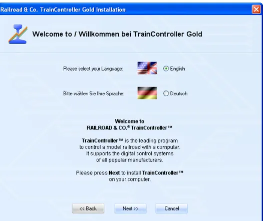
After starting SETUP.EXE or TCSSETUP.EXE, respectively, a self-explaining window is displayed, that guides you through the steps, that are necessary to install
Diagram 1: TrainController™ Setup Screen
Ensure, that you select the right language, because the selected language will also appear later, when running TrainController™.
Before you start TrainController™ you should connect your digital system which you are using to control your model railroad, to the computer. Please refer to the instructions
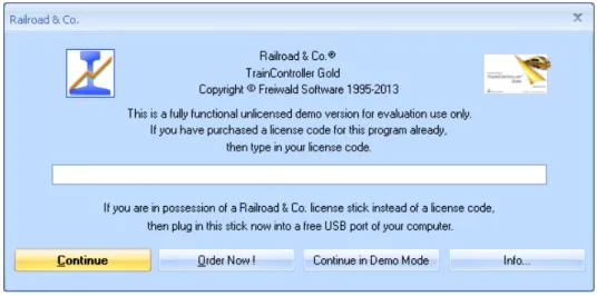
Diagram 2: License Inquiry
When the program starts the software first asks for your license key. Do not be con-cerned, if you are not yet in possession of such key. Press Continue in Demo Mode, if you want to try the software before buying it.
If you are already in possession of a license, then enter the license key here or plug in the Railroad & Co. license stick into a free USB port of your computer and press Con-tinue.
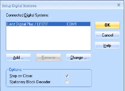
In the next step the connected digital system is configured. Usually the following screen appears automatically, when the program is started for the first time. If the program starts without displaying the screen shown below, then call the Setup Digital Systems
Diagram 3: Setup Digital Systems dialog
If your digital system and/or the serial or USB port of your computer, to which your dig-ital system is connected, is not displayed correctly, press Change to select the right set-tings.
In order to test, whether the connection to the digital system is properly established, play around a little bit with the Power Off and Power On command of the Railroad menu. These commands stop or start your digital system, respectively. Your digital system should respond accordingly to these commands. If your digital system does not respond or if there are some error messages displayed, then do not proceed any further, until this problem is resolved. In case of problems in this area, check very thoroughly, that the digital system is properly connected to the computer according to the manufacturer’s in-structions.
Quick Start - Step 2:
Controlling a Train
Preparing a Train for Model Railroad Computer Control
First put a train onto the tracks of your layout and run it with your digital system. This step is recommended to verify, that the digital system and the train are running correctly and also to bring the digital address of the train back to your mind. This is needed a few moments later.
Now ensure, that the Edit Mode option in the View menu is active.
Diagram 4: View Menu
In this mode it is possible to enter new data into the software or to change existing data. This is what we want to do next.
Call the New Train Window command of the Window menu. If this is done correctly, the following window will appear on your computer screen:
Diagram 5: Train Window
If you want to learn more about the various controls of this window, please refer to chapter 3, “Train Control”.
This is one of the most important commands of TrainController™. It is used for all ob-jects contained in the software (trains, turnouts, signals, routes, etc.), whenever you want to change the settings of a particular object. The following window is displayed now:
Diagram 7: Specifying the Digital Address
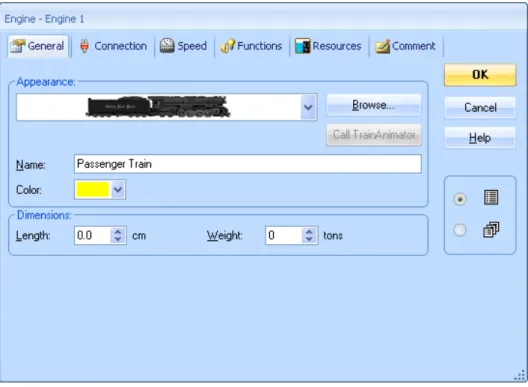
Specify the same address, that you have been using previously to control the train with your digital system, in the field labeled Address. If you want to give your engine a name, that is more easy to remember, select the tab labeled General and enter an appro-priate name. In the following we want to call this train “Passenger Train”.
Diagram 8: Entering a Name
You may have noticed, that the term “train” is being used here, while the images show the term “engine”. If you want to read more about this difference, refer to section 3.2, “Engines”. In the following we will continue using the more general term “train”. Now press OK to close the dialog and to commit these changes. We will now return to the main screen and are ready to control the train:
Controlling a Train
Diagram 9: Train Window
You may notice, that the color of some controls in the train window changed. This hap-pened due to the fact, that we entered a digital address for our train. Now the software knows, how to control the train. To prove this move the mouse to the green control in the centre of the window. Click on it and drag the green control to the right. If every-thing has been done correctly so far, the train will slowly start to move. We have done the first successful step into model railroad computer control!
Before continuing I suggest that you enjoy playing with the train. Play around with the green control, which is actually an on-screen throttle. Drag it to the right and back to ze-ro, then to the left and watch, how your train responds to these actions. See, how the speedometer needle above of the throttle indicates the scale speed of your running train. Watch the odometer increasing. By clicking the green arrow you will reverse the direc-tion of your train. Dragging the red control, which is located between the throttle and the green arrow, will slow down the train. This control is actually a brake control. It can be used by experienced users, to apply the brake to a running train.
There are many more things, that TrainController™ can do for realistic control of your trains. You can operate auxiliary functions (light, whistle, coupler, etc.), simulate the consumption of resources, adjust the momentum to your personal needs and scale the speed and distance measurements to the physical characteristics of your train. This is discussed in detail in chapter 3, “Train Control”.
Quick Start - Step 3:
Controlling Turnouts – The Switchboard
Creating a small switchboard control panel
So far the area in the background of the main window of TrainController™ is still empty. It contains a number of cells, that are arranged in rows and columns. These cells are still empty. We want to fill this empty area with a small switchboard control panel for the following small track layout:
Diagram 10: Small Sample Layout
In the first step we will draw the track diagram in the switchboard window. First ensure that Edit Mode in the View menu is still turned on (see Diagram 4). Next select the
Diagram 11: Tools Menu
Now move the mouse to the cell in the switchboard window, where the left end of our track diagram will be located. Click and hold the left mouse button and drag the mouse about 25 cells to the right. Then release the left mouse button. The following image should now be visible in the switchboard window:
Diagram 12: Straight track section
We have drawn a straight track section. Now move the mouse to a cell on this track sec-tion, that is located about one third to the right of the left end. Click the left mouse but-ton and drag the mouse one cell to the right and one cell up. Then release the left mouse button. Now you should see something similar to the following:
Diagram 13: Track section with turnout
The first turnout in the switchboard has now been created. Now click on the cell, where the diverging route of this turnout ends and drag the mouse to the right to a cell, that is located about one third left of the right end of the straight track section.
Diagram 14: Extending the track diagram
Finally click on the cell, where the last mouse movement ended, and drag the mouse one cell to the right and one cell down.
Diagram 15: The complete track diagram
The track diagram of our small sample layout is now complete and should look like Di-agram 15.
If you want to operate real turnouts of your existing model railroad with the track dia-gram control panel just created, try to identify a small area of your layout, that contains a similar track structure with two turnouts as shown above. Now operate these turnouts
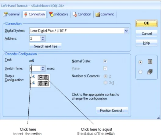
Now click on the symbol of the left turnout in the track diagram and select the Proper-ties of the Edit menu. Do you remember? This command is used for all objects con-tained in the software (trains, turnouts, signals, routes, etc.), whenever it is required to change the settings of the particular object. The following window is now displayed:
Diagram 16: Specifying the Digital Address
Specify the same address, that you have been using previously to control the correspond-ing real turnout with your digital system, in the field labeled Address. Now click on the symbol of the turnout, that is located to the right of the label Test. The real turnout on your model railroad layout should now respond. Depending on the wiring of your turn-out it is possible, that the image in the software and the physical turnturn-out do not show the same status (closed vs. thrown). If this is the case click on the grey circle in the upper row of the Output Configuration to adjust the displayed status (see Diagram 16). The
of the turnout and the status of the turnout should be in sync, when you test the turnout again. Note, that the layout of this area may vary with the connected digital system. Some advanced background information: in many cases, dependent on the digital system used, the highlighting in the Output Configuration will reflect the keys, that are to be pressed on the handheld of your digital system to set the turnout (or any other accessory, that is operated by turnout commands) to the corresponding state. Whenever the display of the turnout on the computer screen and the status of the turnout on your layout are not in sync, then you should operate the turnout first with your handheld and remember the keystrokes used to achieve a certain state. You should then translate these keystrokes to the Output Configuration of this turnout.
If you want to give your turnout a name, that is easier to remember, select the tab la-beled General and enter an appropriate name.
Now press OK to close the dialog and to commit these changes. We will now return to the main screen and are ready to control the turnout. To do this, turn off Edit Mode in the View menu (see Diagram 4), move the mouse to the symbol of the turnout in the track diagram of the switchboard window, click on this symbol and watch, how the real turnout on your layout responds.
Finally perform the same for the right turnout symbol in the track diagram.
We are now able to control a train and a small layout manually with the computer. I suggest that you run the train back and forth on this small layout a little bit and play with different routes by changing the positions of each turnout prior to each run of the train. In the next step we will learn, how trains can be operated automatically under control of the computer.
Quick Start - Step 4:
Creating Blocks - Tracking Train Positions
Equipping the layout with feedback sensors
The most important prerequisite for controlling trains automatically with your computer or to monitor the movements of trains on the computer screen is equipping the layout with feedback sensors. These sensors are used to report train movements back to the computer. Based on this information TrainController™ is able to take the right deci-sions to direct automatically running trains to their destination or to monitor the move-ment of trains.
Two types of feedback sensors can be used: occupancy sensors and momentary track contacts. Details of this difference and more detailed information about feedback sen-sors can be found in chapter 4, “Contact Indicators”.
In the following we assume, that occupancy sensors are used to control our small layout and that our layout is divided into four detection sections according to the following im-age:
Diagram 17: Detection Sections and Occupancy Sensors
There are other ways to divide a layout into detection sections or to control it with mo-mentary track contacts. Further, the scheme displayed above is also not necessarily the optimal solution. The above scheme has been chosen for this tutorial for reasons of sim-plicity and because it is sufficient to perform a quick start. Other variants for equipping your layout with feedback sensors are outlined in more detail in section 5.8.
Dividing the layout into Blocks
Another important prerequisite for controlling trains automatically with your computer or to monitor the movements of running trains is separating the layout into logical blocks. Blocks are the base elements for automatic train control and tracking of train po-sitions. There is a close relation between feedback sensors and blocks: each block is as-sociated with one or more feedback sensors.
There are certain guidelines for creation of blocks. They are outlined in detail in section 5.2, “Blocks”. According to these guidelines we divide our small sample layout into blocks as shown below:
Diagram 18: Dividing a layout into Blocks
As you can see we have applied a 1:1 relation between blocks and detection sections here. Please note, that this is not always the case. In many cases more than one detection section or feedback sensor will be associated with one block. However, it is also possi-ble to control your layout or appropriate parts of it with one feedback sensor per block. For reasons of simplicity and because it is sufficient for the quick start we go with one detection section per block here, too. Please keep in mind, however, that blocks and de-tection sections are not the same thing.
More details about this topic are outlined in detail in section 5.6, “Blocks and Indica-tors”.
Entering the locations of Blocks into the Switchboard
Diagram 19: Tools Menu
Now click on the cell, that is located right of the cell, that contains the left end of our track diagram. A block will appear at this location.
Diagram 20: Block in the Switchboard
Please do the same for the three other blocks. Note, that the cell, where you click, de-termines the leftmost end of the block. Ensure also, that you click on a cell, that contains a piece of straight track.
If everything was done correctly, the track diagram should look like the following im-age:
Diagram 21: The complete Track Diagram with all Blocks
Assigning Feedback Sensors to Blocks
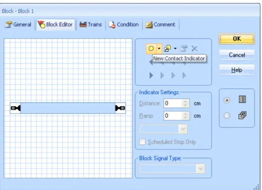
There is a close relation between feedback sensors and blocks: each block is associated with one or more feedback sensors. To assign a feedback sensor to a block, select “Block 1” in the switchboard track diagram and call the Properties command of the Ed-it menu.
Diagram 22: Block Editor
It shows the properties of the block and indicates, that no sensor is yet assigned to this block.
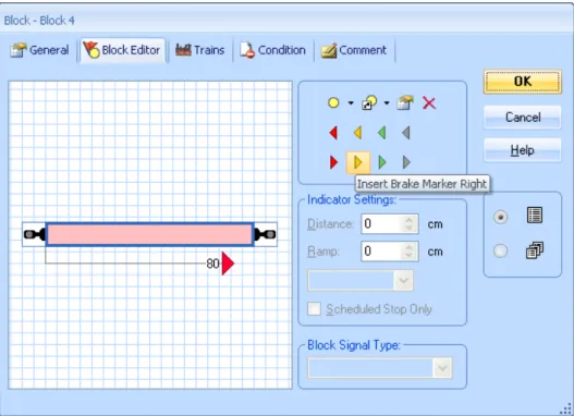
Click on in the tool bar of the block editor. This is the item, which is highlighted in Diagram 22. The block editor now changes as follows:
Diagram 23: Block Editor with Contact Indicator
The center of the block editor now shows a reddish rectangle. This rectangle is called contact indicator and represents the occupancy section within the block, which is moni-tored by the feedback sensor.
Now click on the contact indicator (i.e. the reddish rectangle) and then click on the
Properties command in the tool bar of the block editor. This is the highlighted sym-bol in Diagram 23. The dialog box displayed below is opened:
Diagram 24: Specifying the Digital Address of a Contact Indicator
Now specify the digital address of the feedback sensor, that belongs to this contact indi-cator. In most cases this is the digital address of the feedback decoder and the number of the contact input of this decoder, to which the sensor is connected.
To test your settings, put a train or anything else, that is suited to trigger a feedback event, into the detection section, that corresponds to “Block 1”. The block in the track diagram in the switchboard should now change its color to red:
Diagram 25: Indication of an occupied Block
If this has been done correctly, the blocks in the switchboard will change their color ac-cording to the movements of your train on the layout. Play around a little bit with your train and watch how the blocks in the switchboard are indicated.
Displaying train positions on the Computer Screen
Now we are ready for train tracking, i.e. displaying of train positions on the computer screen.
To do this move your real train into “Block 1”, if it is not located there already. Ensure, that the train is heading towards the other blocks, i.e. that it has to run forward, in order to go to “Block 2” or “Block 3”, respectively.
Then turn off Edit Mode in the View menu (see Diagram 4). Next select “Block 1” in the switchboard and call the Assign Train command of the Block menu according the following image:
Diagram 26: Block Menu
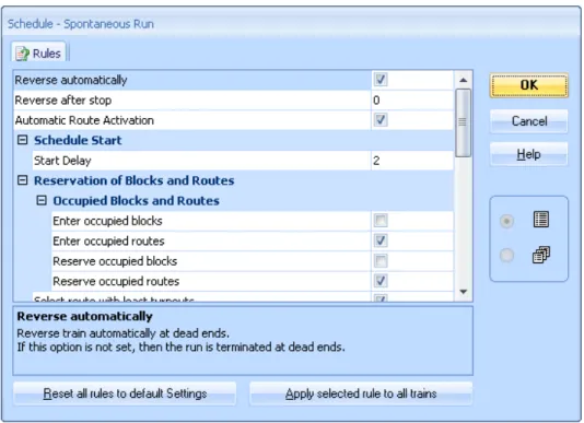
In the following dialog select the “Passenger Train” and select the train orientation by marking the option near the arrow pointing to the right.