DigitalMicrograph 3.4
User’s Guide
Gatan, Inc.
5933 Coronado Lane Pleasanton, CA 94588 Tel (925) 463-0200 FAX (925) 463-0204November 1999
Revision 1
DigitalMicrograph 3.4 User’s Guide i
Preface
About this Guide
This DigitalMicrograph 3.4 User’s Guide is written for use with DigitalMicro-graph 3.4. This Guide provides detailed discussion on the use of the program as a stand-alone application to visualize, analyze, and process digital image data obtained from many different means.
Preview of this Guide
The DigitalMicrograph 3.4 User’s Guide includes the following chapters: Chapter 1, “Overview,” describes the program and presents an overview of the “DigitalMicrograph” process.
Chapter 2, “Basic Procedures,” describes the process for launching Digi-talMicrograph and the various image document manipulation procedures, i.e., opening, saving, printing, etc.
Chapter 3, “Images,” describes the basics of image documents, i.e., data types, memory, calibrations, etc.
Chapter 4, “Image Display,” describesthe different methods used to display images and to convert images from one type to another.
Chapter 5, “Image Documents,” describes the methods used to generate, manipulate, and edit objects and annotations in an image document.
Chapter 6, “Basic Image Analysis,” describes the use of various image analy-sis processes, such as the use of line profiles, histograms, etc.
Chapter 7, “Basic Image Processing,” describes the use of various image pro-cessing methods, such as, filtering, convolutions, etc.
Chapter 8, “Fourier Processing,” describes the basics of Fourier transforms used in DigitalMicrograph.
Chapter 9, “Particle Analysis,” describes the basics of Particle Analysis used in DigitalMicrograph.
Chapter 10, “Scripting,” describes the DigitalMicrograph Scripting Language and the Script online help.
Disclaimer
Gatan, Inc., makes no express or implied representations or warranties with respect to the contents or use of this manual, and specifically disclaims any implied warranties of merchantability or fitness for a particular purpose. Gatan, Inc., further reserves the right to revise this manual and to make changes to its contents at any time, without obligation to notify any person or entity of such revisions or changes.
Copyright and Trademarks
© 1999. All rights reserved.
DigitalMicrograph® is a registered trademark of Gatan. Inc., registered in the United States.
MultiScan® is a registered trademark of Gatan. Inc., registered in the United States.
DigitalMicrograph 3.4 User’s Guide iii
Support
Contacting Gatan Technical Support
Gatan, Inc., provides free technical support via voice, Fax, and electronic mail. To reach Gatan technical support, call or fax the facility nearest you or contact by electronic mail:
• Gatan, USA (West Coast) Tel: (925) 463 0200 Fax: (925) 463 0204 • Gatan, USA (East Coast)
Tel (724) 776 5260 Fax: (724) 776 3360 • Gatan, Germany Tel: 089 352 374 Fax: 089 359 1642 • Gatan, UK Tel: 01536 743150 Fax: 01536 743154 • Gatan, Japan Tel: 0424 38 7230 Fax: 0424 38 7228 • Gatan, France Tel: 33 (0) 1 30 59 59 29 Fax: 33 (0) 1 30 59 59 39 • Gatan, Singapore Tel: 65 235 0995 Fax: 65 235 8869 • Gatan Online http://www.gatan.com [email protected] [email protected]
DigitalMicrograph3.4 User’s Guide v
Table of Contents
Preface i Support iii Table of Contents v List of Figures ix 1 Overview 1-1 1.1 Introduction 1-11.2 The DigitalMicrograph Process 1-2 1.3 Basic Concepts 1-3
1.4 Using this Guide (first time users) 1-4 1.5 Using this Guide (upgrade users) 1-4
2 Basic Procedures 2-1
2.1 Starting DigitalMicrograph 2-2
2.2 Creating/Opening Image Documents 2-3 2.3 Using Image Windows 2-5
2.4 Saving an Image Document 2-7 2.5 Printing Image Documents 2-10
2.6 Closing Image Documents and Exiting 2-11 2.7 Using Text Windows 2-12
2.8 Using Floating Palettes 2-13
3 Images 3-1
3.1 About Images 3-1
3.2 Setting Image information 3-4
4 Image Display 4-1
4.1 Visualizing Images 4-1
4.2 Using Raster Image Displays 4-2 4.3 Using Surface Model Image Displays 4-5 4.4 Using Surface Plot Image Displays 4-8
4.5 Using Image Displays with Color Transformations 4-10 4.6 Using Image Displays with Complex Data 4-20 4.7 Using RGB Image Displays 4-21
4.8 Using Line Plot Image Displays 4-22 4.9 Using Spreadsheet Image Displays 4-27
5 Image Documents 5-1
5.1 About Image Documents 5-1 5.2 Manipulating Objects 5-3 5.3 Editing 5-8
5.4 Adjusting the Target 5-9 5.5 Setting Object Information 5-10
5.6 Boxes, Ovals, Lines, Arrows, and Text 5-12 5.7 Saving Image Documents 5-15
5.8 Importing Images 5-16
6 Basic Image Analysis 6-1
6.1 Using Image Regions of Interest 6-1 6.2 Using Line Profiles 6-7
6.3 Calculating Image Statistics 6-9 6.4 Using Calibrations 6-10 6.5 Using Histograms 6-14 6.6 Using the Slice Tool 6-15
6.7 The Progress and Acquisition Palettes 6-16
7 Basic Image Processing 7-1
7.1 Changing Data Types 7-1
7.2 Using Basic Image Transformations 7-5 7.3 Using Filtering 7-8
DigitalMicrograph 3.4 User’s Guide vii 8 Fourier Processing 8-1
8.1 Using Fourier Transforms 8-1 8.2 Using Fourier Masking 8-5
9 Particle Analysis 9-1 9.1 Image Preparation 9-1 9.2 Thresholding 9-3 9.3 Finding Particles 9-5 9.4 Analyzing Particles 9-7 10 Scripting 10-1 10.1 Using Scripts 10-1 10.2 Writing Scripts 10-5 Index I-1
DigitalMicrograph 3.4 User’s Guide ix
List of Figures
Figure 1-1 Typical acquisition setup. 1-2
Figure 2-1 The DigitalMicrograph Workplace. 2-2 Figure 2-2 Open File dialog (MacOS and Windows). 2-4 Figure 2-3 Image window and controls. 2-6
Figure 2-4 Save As dialog. 2-8 Figure 2-5 Results window. 2-12 Figure 2-6 Floating palettes group. 2-14 Figure 2-7 Global Info—Data Bar. 2-15 Figure 2-8 Global Info—Auto-save. 2-16 Figure 2-9 Global Info—Page. 2-17 Figure 2-10 Global Info—Keywords. 2-18 Figure 2-11 Global Info—Tags. 2-19 Figure 3-1 Image Status. 3-4
Figure 3-2 Object Info—Image–Info. 3-5 Figure 3-3 Object Info— Image–Keywords. 3-7 Figure 3-4 Object Info— Image–Tags. 3-8 Figure 4-1 Display Type submenu. 4-2 Figure 4-2 Raster image display. 4-3
Figure 4-3 Raster image display with Captions. 4-4 Figure 4-4 Object Info—Captions–Captions. 4-4 Figure 4-5 Image Status for Raster image display. 4-5 Figure 4-6 Surface Model image display. 4-5
Figure 4-8 Surface Model 3D tools. 4-7 Figure 4-9 Surface Plot image display. 4-8
Figure 4-10 Object Info—Surface Plot–Shading. 4-9 Figure 4-11 Histogram palette. 4-11
Figure 4-12 Object Info—Display–Contrast. 4-13 Figure 4-13 Survey Method pop-up menu. 4-13 Figure 4-14 Mode pop-up menu. 4-15
Figure 4-15 Object Info—Display–Color. 4-16 Figure 4-16 Brightness/Contrast/Gamma control. 4-18 Figure 4-17 Image Display—Display -Display. 4-19
Figure 4-18 Display Control palette—Contrast/Contours. 4-20 Figure 4-19 Object Info—Display–Complex. 4-20
Figure 4-20 Complex Display pop-up menu. 4-21 Figure 4-21 RGB image display. 4-21
Figure 4-22 RGB pixel values in Image Status palette. 4-22 Figure 4-23 Line Plot image display. 4-22
Figure 4-24 Line Plot pixel values in Image Status palette. 4-23 Figure 4-25 Object Info—Display–Line Plot. 4-24
Figure 4-26 Object Info—Display–Options. 4-25 Figure 4-27 Object Info—Display–Placement. 4-26 Figure 4-28 Line Plot Tools. 4-26
Figure 4-29 Spreadsheet Image Display. 4-27 Figure 4-30 Editing a RGB spreadsheet cell. 4-27 Figure 5-1 Graphical page representation. 5-2 Figure 5-2 Control palette for a line. 5-3
Figure 5-3 Object Info—Display–Placement. 5-5 Figure 5-4 Control palette for Raster image display. 5-6 Figure 5-5 Align submenu. 5-8
Figure 5-6 Target palette. 5-10
Figure 5-7 Object Info—Object–Tags. 5-11 Figure 5-8 Standard Tools palette. 5-12
DigitalMicrograph 3.4 User’s Guide xi
Figure 5-11 Annotation background. 5-14 Figure 5-12 Text alignment. 5-15 Figure 5-13 Import Image dialog. 5-16 Figure 6-1 Selection palette. 6-1
Figure 6-2 Raster image display with rectangular region of interest. 6-2 Figure 6-3 Raster image display with line of interest. 6-3
Figure 6-4 Raster image display with points of interest. 6-3
Figure 6-5 Raster image display with closed-loop region of interest. 6-4 Figure 6-6 Raster image display with open-line region of interest. 6-4 Figure 6-7 Line Plot image display with regions of interest. 6-5 Figure 6-8 Spreadsheet image display with region of interest. 6-7 Figure 6-9 Line Profile tool. 6-7
Figure 6-10 Line Profile and Line Plot. 6-8 Figure 6-11 Change Profile Info dialog. 6-8 Figure 6-12 Profile Line with integration. 6-9 Figure 6-13 Statistics submenu. 6-10
Figure 6-14 Results of statistics calculations. 6-10 Figure 6-15 Object Info—Image–Calibration. 6-11 Figure 6-16 Target palette. 6-11
Figure 6-17 Calibration dialog. 6-13 Figure 6-18 Image with Scale Marker. 6-14 Figure 6-19 Histogram options. 6-15 Figure 6-20 Histogram. 6-15 Figure 6-21 Slice window. 6-16
Figure 6-22 Slice tool displayed in center units. 6-16 Figure 6-23 Progress palette. 6-16
Figure 6-24 Acquisition Status palette. 6-17 Figure 7-1 Change Data Type dialog. 7-2 Figure 7-2 Convert Data Type dialog. 7-3
Figure 7-3 Complex Conversion Method dialog. 7-3 Figure 7-4 RGB Conversion Method dialog. 7-4 Figure 7-5 Construct RGB Image dialog. 7-5 Figure 7-6 Rotate dialog. 7-6
Figure 7-7 Scale Image dialog. 7-7 Figure 7-8 Dimension Unit submenu. 7-7 Figure 7-9 Resample Method submenu. 7-7 Figure 7-10 Spatial filter submenu. 7-8 Figure 7-11 Non-linear filter submenu. 7-9 Figure 7-12 Sharpen kernel. 7-9
Figure 7-13 Smooth Kernel. 7-9 Figure 7-14 Laplacian kernel. 7-10 Figure 7-15 Sobel kernels. 7-10 Figure 7-16 Median Filter dialog. 7-11 Figure 7-17 Kernel types. 7-12 Figure 7-18 Convolution dialog. 7-13 Figure 7-19 Set Kernel dialog. 7-13 Figure 7-20 Remove Kernel dialog. 7-14 Figure 7-21 Simple Math dialog. 7-15 Figure 8-1 Cross-Correlate dialog. 8-4 Figure 8-2 Masking Tools. 8-6
Figure 8-3 Twin Oval Mask on image. 8-7 Figure 8-4 Band Pass Mask on image. 8-7 Figure 8-5 Periodic Mask on image. 8-8
Figure 8-6 Object Info—Periodic Array–Options. 8-9 Figure 8-7 Periodic Mask representing multiple units. 8-9 Figure 8-8 Wedge Mask on image. 8-10
Figure 8-9 Apply Filter Options dialog. 8-11 Figure 8-10 Image with union of two masks. 8-11
Figure 8-11 Image with the intersection of two masks. 8-12 Figure 9-1 Rice image. 9-2
Figure 9-2 Rice background image. 9-2 Figure 9-3 Rice image flattened. 9-3 Figure 9-4 Histogram of Rice image. 9-3 Figure 9-5 Rice image with threshold. 9-4 Figure 9-6 Magic Wand tool. 9-5
DigitalMicrograph 3.4 User’s Guide xiii
Figure 9-8 Configure Particles dialog. 9-8
Figure 9-9 Rice image with analyzed particles. 9-9 Figure 9-10 Measurements on Rice image. 9-9 Figure 10-1 Script window. 10-2
Figure 10-2 Install script as a menu. 10-3 Figure 10-3 Install script as a library. 10-3 Figure 10-4 Remove Script dialog. 10-4
DigitalMicrograph 3.4 User’s Guide 1-1
1 Overview
DigitalMicrograph™ is an application used for acquiring, visualizing, analyz-ing, and processing digital image data, primarily within the context of electron microscopy. It can be thought of as an environment that can be enhanced with different attachments (plug-ins) to perform a variety of analytical tasks.
1.1 Introduction
How does the DigitalMicrograph process work? With DigitalMicrograph and one of the acquisition units, such as a CCD camera, you can acquire a digital image of a sample, manipulate its display, analyze, process, print, and archive it for long-term storage.
Full image-acquisition power
DigitalMicrograph provides the capability, through the use of plug-in exten-sions to the application, to control and acquire images and data from CCD cam-eras, EELS systems, imaging filters, and a variety of other sources.
Visualization, processing, and analysis algorithms
DigitalMicrograph gives you many different ways to view your data and images. It also provides you with a full complement of image processing algo-rithms and analysis techniques for coming to grips with the information con-tained within your data.
Flexible page design and presentation
Presentation of your data in DigitalMicrograph is easy and flexible. You can collect many images onto a single page, size them the way you want relative to the page, arrange them within the page, and print them.
The DigitalMicrograph Process
Extensive storage options
DigitalMicrograph supports all of the top industry standards for storing files. You can open and store TIFF, GIF, PICT, BMP, and other formats using Digi-talMicrograph.
1.2 The DigitalMicrograph Process
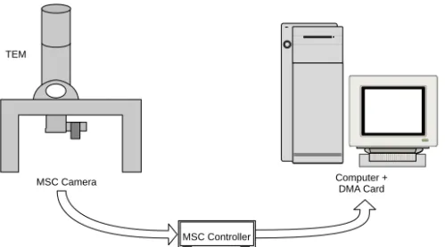
DigitalMicrograph eliminates many of the steps you perform when using film, but acquiring an image within DigitalMicrograph is still analogous to obtaining an image on film. An example of an electron microscope with a CCD camera (imaging device) interfaced to a computer is shown in Figure 1-1.
Figure 1-1 Typical acquisition setup.
The image is formed in the microscope and digitized by the CCD camera. The data is then sent to the camera Controller where it is converted to a form that the computer can read. The DMA (direct memory access) card transfers the data from the Controller into the computer’s memory where DigitalMicrograph can access the data
A DigitalMicrograph session would typically follow a procedure similar to the following:
1. Acquire your data.
DigitalMicrograph allows you to acquire data from many different sources such as CCD cameras, EELS systems, or imaging filters. Your data may be an image, a spectrum, or something totally different.
MSC Controller
Computer + DMA Card MSC Camera
Basic Concepts
DigitalMicrograph 3.4 User’s Guide 1-3
You may be analyzing data that already exists in a file. Acquisition would then consist of simply loading the file into DigitalMicrograph.
2. Visualize your data.
DigitalMicrograph can display data and images in many ways. You can dis-play images in a format similar to a photograph, as a surface plot or surface model display (three-dimension representations), as a numerical spreadsheet display, or as a one-dimensional line plot.
3. Analyze your data.
You can measure areas and lengths, perform various statistical and mathe-matical calculations for analysis, and analyze particles present in your image.
4. Process your data.
You can enhance your image by performing Fourier filtering, sharpening, or other types of image processing.
5. Present your data.
The most important result of the entire process is the presentation of your data. You can arrange multiple images on a page and annotate your images and page through the use of text, lines, boxes, ovals, or clip-art imported from other applications.
DigitalMicrograph makes it easy to arrange multiple images and other anno-tations on a page to produce the layout you desire.
6. Archive your data.
At each part of this process, you should be saving your data to disk. The beauty of digital processing is that if you do this at each step of the process, you can always return to a previous step and try again.
In the end, however, you will want to save your data to a long-term storage medium where it can be found and retrieved in the future. DigitalMicro-graph gives you many choices and formats for saving data to disk. It also integrates with archiving applications for keeping track of the images that you acquire and generate.
1.3 Basic Concepts
DigitalMicrograph presents all of its information through the use of windows. Each window contains a set of related information.
Using this Guide (first time users)
Image document windows contain a visible representation of a page of paper. Images can be placed on this page. Other objects such as lines, boxes, and text can also be placed on this page. You can open, save, and print image document windows.
Many aspects of images and objects placed on pages can be controlled through the use of palettes. Palettes “float” above image document and text document windows. You cannot open, save, or print palettes. Palettes are distinguished by their small title bar under Windows and have no title in their title bar on the MacOS.
Text document windows contain text. Text document windows do not hold any other graphical objects. You can open, save, and print text document windows. DigitalMicrograph can be extended to support acquisition devices through the use of plug-ins. Plug-ins are placed in a folder named “Packages” under the MacOS and “PlugIns” under Windows.
DigitalMicrograph can also run simple programs (called scripts) which carry out automated tasks.
1.4 Using this Guide (first time users)
This Guide will be your reference while using DigitalMicrograph. It contains step-by-step instructions for most tasks you will perform.
This Guide deals with general areas of DigitalMicrograph such as displaying images, analyzing images, processing images, presenting images, and storing images. The table of contents of this Guide lists the chapters and the main head-ings within each chapter.
1.5 Using this Guide (upgrade users)
This Guide describes an improved version of DigitalMicrograph.
If you are upgrading from DigitalMicrograph 2.5, you should read over this entire manual as many things have changed. Most notably, DigitalMicrograph 3.4 has page-layout capabilities and the ability to contain multiple independent images within a single window.
If you are upgrading from DigitalMicrograph 3.1, you should note the improve-ments in page/image mode and improveimprove-ments in the Line Plot image display.
DigitalMicrograph 3.4 User’s Guide 2-1
2 Basic Procedures
DigitalMicrograph lets you acquire, process, analyze, and present your images through its easy-to-use commands and tools. Once you master the basics of using DigitalMicrograph, you’ll want to learn more about the application and add more skills to your arsenal. This chapter assumes you are familiar with the basic ideas of the mouse, manipulating windows and menus, and launching applications on your computer. If you are not, please refer to the manual that came with your computer.
The DigitalMicrograph Workplace
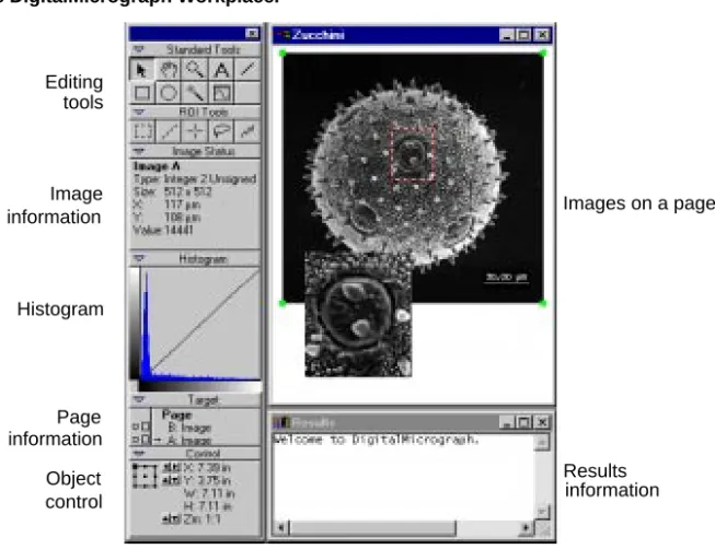
DigitalMicrograph displays images within image windows. There are other types of windows (called palettes) that allow you to manipulate details of those images and other objects. Still other types of windows give you information about an image or the results of analysis or processing algorithms. Figure 2-1 shows examples of all of these types of window.
Image windows can display images one at a time (image mode) or more than one at a time (page mode). When the image window is in image mode, the image is the main focus of the window. The image will resize when you change the size of the window and any operations you perform will take place on the image. When the image window is in page mode, a page will be displayed and multiple images can be laid out on the page. Operations involving images will apply to the image that is selected on the page. You can switch between image mode and page mode using the Target floating palette.
Note: Since an image window can display either a single image or a page con-taining zero or more images, we will refer to the contents of the image window as an image document. The image document term will be taken to mean zero or more images laid out on a page and viewed either as a page or as a single view of one of the images.
Starting DigitalMicrograph
Window settings can suit your preferences
Individual windows and palettes in DigitalMicrograph can be adjusted in sev-eral ways to suit your preferences. You can zoom in or out to view more or less detail in your window, resize the window, and more. You can also adjust the floating palettes, tools, and other gadgets to suit your needs.
Saving documents to be secure
If you’ve worked with a computer, you already know the importance of saving your work often. Saving your image documents frequently avoids the pain of losing a day’s work when the power fails unexpectedly. Saved image docu-ments also give you a record of your progress and a place to restart from if an experimental processing algorithm doesn’t produce the results you desire.
Figure 2-1 The DigitalMicrograph Workplace.
2.1 Starting DigitalMicrograph
Before you can use DigitalMicrograph, you must install it on your computer according to the instructions contained in the Installing DigitalMicrograph
manual.
You start DigitalMicrograph just as you would any other applications on your tools information Image information Page control Object Images on a page Results Editing Histogram information
Creating/Opening Image Documents
DigitalMicrograph 3.4 User’s Guide 2-3
To start DigitalMicrograph
You launch DigitalMicrograph as you would any other application.
• Under the MacOs, find the DigitalMicrograph icon and double-click it. • Under Windows, select DigitalMicrograph from the Start menu. By choosing commands from the menu bar, you can now create a new image window, open an existing one, or acquire one from an acquisition device.
2.2 Creating/Opening Image Documents
After you’ve launched DigitalMicrograph, you begin to work with an image by either acquiring a new one from an acquisition device such as a camera, creating a new one, or opening an existing one.
To acquire a new image
You can acquire an image with an acquisition device such as a CCD camera, EELS system, DigiScan, or imaging filter.
To acquire from an external device, use the plug-in supplied with the device. For example, the plug-in supplied with the MSC camera will present you with a floating command palette through which you can control the camera. See the manual provided with your acquisition device for specific details on acquiring an image.
Any images you acquire will automatically appear in image mode. To create a new image manually
You can create a new image manually. 1. Choose NEW from the FILE menu.
2. Click on the Image tab at the top of the dialog.
3. Enter a name for the image window which will contain the new image. 4. Enter a width and height for the image.
You can choose a width and height of 200 x 200 for experimental purposes. 5. Change the display type to “Raster.”
This indicates that the image will be displayed in a format similar to a pho-tograph.
Creating/Opening Image Documents
6. Change the data type to “Real” with “4 bytes.”
This generates an image that can hold real numbers (as opposed to integers, or complex numbers).
7. Select a pattern and click OK.
This operation will actually create an image document with a single image and display that image document in image mode.
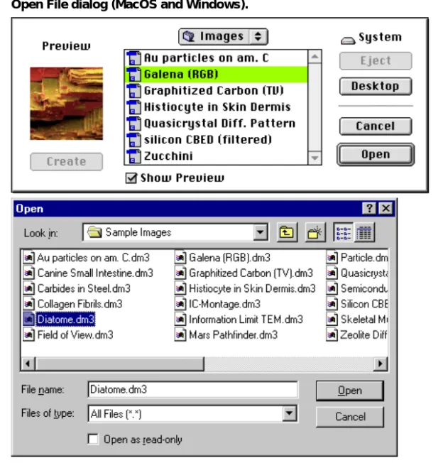
To open an image from disk
You can open an existing DigitalMicrograph image document or you can open images created in other applications and saved in formats DigitalMicrograph understands, such as TIFF, GIF, BMP, JPEG, and PICT under the MacOS. 1. Choose OPEN from the FILE menu.
2. Select the image document or image you want to open.
Using Image Windows
DigitalMicrograph 3.4 User’s Guide 2-5
3. Click OPEN.
The image will open immediately.
DigitalMicrograph will alert you if it does not recognize the file type. In order to open images that are not in the Gatan DigitalMicrograph file format, you will need to install the “Import/Export Plug-in” (which is shipped with Dig-italMicrograph).
To create an empty image document
You can create an empty image document that will be displayed in page mode on which you can place images from other windows.
1. Choose NEW from the FILE menu.
2. Click on the Document tab at the top of the dialog. 3. Enter a name for the image document.
4. Click OK.
An empty image document will be displayed in page mode. You will see a rep-resentation of the page in the window.
2.3 Using Image Windows
DigitalMicrograph provides several ways to customize an image window. Among other things, you can magnify your view of the document, change the page size, and move the image and page around within the window.
To resize the window
Resize the window as you would resize any window on your operating system. • To resize manually under MacOS, click and drag the Resize box. • To resize manually under Windows, click and drag an edge of the
win-dow.
If the image document is current in image mode, hold down the Option key under the MacOS or the Alt key under Windows to keep the image sized to an integer multiple of its size during resizing; otherwise the image will be resized to be as large as possible within the window.
If the image document is currently being viewed in page mode, the page will always be sized to fit as large as possible within the window.
Using Image Windows
Figure 2-3 Image window and controls.
• To resize around either the image or the page under the MacOS, click in the zoom box.
• To resize around either the image or the page under Windows, click in the maximize box.
Resizing an around an image or page will size the window so that the image or page fits exactly within the window at its current resolution.
To change printed page size or orientation You can change the size or orientation of the page. • Select PAGE SETUP from the FILE menu.
Enter the desired size and orientation in the dialog that is presented. To change the magnification of the image document
You can change the size at which DigitalMicrograph displays the image or the page within the window.
• Click in the image window with the Magnify Page tool.
The Magnify Page tool will display a “+” inside the magnifying glass to indicate you will be magnifying around the point at which you click.
Move Page tool
Magnify Page tool Pointer tool
Saving an Image Document
DigitalMicrograph 3.4 User’s Guide 2-7
Hold down the Option key under the MacOS or the Alt key under Windows to demagnify. The Magnify Page tool will display a “-” inside the magnify-ing glass to indicate you will be demagnifymagnify-ing.
To move the image around within the window (page mode only) You can move the image within the window.
• Click and drag the image within the image document with the POINTER
tool.
To move the page around within the window You can move the page within the window.
• Click and drag the page within the image document with the Move Page tool.
2.4 Saving an Image Document
As you work, save early and often; don’t wait until you finish working or until “later.” This will prevent you from losing images due to power failures and other unexpected circumstances.
Since an image document may contain multiple images and some of the file for-mats do not support multiple images, we distinguish between saving an entire image document and exporting an individual image from within an image docu-ment.
When you save in the Gatan file format, the entire contents of the image docu-ment will always be saved and there will be no reduction in data.
When you save an image document using one of the single-image formats (such as TIFF, GIF, BMP, etc.), DigitalMicrograph will save a rendering of the cur-rent view (either an image within the document or the entire page). This render-ing will be saved at screen resolution and there will be a reduction in the amount of data.
You can also export to a specific image file format. This will retain the maxi-mum resolution and data depth available using the particular file format. You need to specify a specific image to export and when you export an image, no annotations will be visible on the image. This is because file formats other than the Gatan file format do not support independent annotations on the image; so placing the annotations on the image would have to overwrite image data.
Saving an Image Document
To save an image document in the Gatan file format You can save your image document to disk at any time. • Choose SAVE from the FILE menu to save current image.
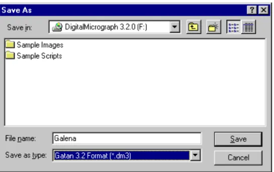
If this is the first time you’ve saved the file, DigitalMicrograph displays the Save As dialog box. Type in name for the file, choose the desired directory, and click SAVE.
Figure 2-4 Save As dialog.
If the image document has already been saved once or was loaded from a file, DigitalMicrograph saves it to the same file, overwriting the previous version.
• Choose SAVE AS from the FILE menu to save to a new file.
DigitalMicrograph displays the Save As dialog box (see Figure 2-4). Type a name for the file, choose the desired directory, and click SAVE.
You can choose another file format within the Save dialog. Remember, how-ever, that saving in any file format other than the Gatan file format will result in a loss of information when reloading the images. This may be appropriate if you’re only interested in loading the image in another application. If you want to be able to get back the original data at full resolution and data depth, you should always save in the Gatan file format. You can also save an image docu-ment in two or more formats independently; just follow the procedure above multiple times.
Saving an Image Document
DigitalMicrograph 3.4 User’s Guide 2-9
To export a specific image from page mode
If your document contains multiple images and you are viewing them on a page, you can export individual images to a specific file format. For instance, if your image document contains three images, you can export one of those three images to a TIFF file format.
1. Select the image you want to export using the POINTER tool.
2. Select the desired file format from the EXPORT submenu under the FILE
menu.
DigitalMicrograph displays the Save As dialog box. Type a name for the file, choose the desired directory, and click SAVE. See Figure 2-4.
Remember, when exporting an image, annotations will not be included in the saved image.
To export your image from image mode
If you are viewing a single image in image mode, you can export that image to a specific file format.
• Select the desired file format from the EXPORT submenu under the FILE
menu.
DigitalMicrograph displays the Save As dialog box. Type a name for the file, choose the desired directory, and click SAVE. See Figure 2-4.
Remember, when exporting an image, annotations will not be included in the saved image.
To save an image with annotations
If you are viewing a single image with annotations and you want to save that image to a specific file format, follow these steps.
1. Resize the window such that the image is displayed at the desired size and resolution.
2. Choose SAVE ASfrom the FILE menu to save current image.
DigitalMicrograph displays the Save As dialog box. Type a name for the file, choose the desired directory. See Figure 2-4.
3. Select the desired format from the file format menu. 4. Click Save to save the image.
Printing Image Documents
To save a series of images
DigitalMicrograph can save image documents in a series of files so that each time you save, the image document gets a new filename.
• Choose SAVE NUMBERED from the FILE menu.
You can set the directory in which to save the image documents, the name of the series, and the number in the series that you want to begin with (see Section 2.9, “Setting Preferences and Information”).
For example, the first time you do this the image document will be saved with the name “Image Series.1.” The next time you do it, the image will be saved with the name “Image Series.2.”
2.5 Printing Image Documents
Image documents can be viewed in image mode or page mode. Freshly acquired images are set to image mode. When you print these images without doing any page layout, they are printed such that they are centered at the top of the page and fill about 90% of the printable area of the page.
To exercise more control over the placement of the image or to add multiple images to the document, switch to page mode and lay out the image(s) as you desire. After you have laid out the image(s) in page mode, whenever you print (even if the image document is being viewed in image mode), DigitalMicro-graph will use the page layout that you specified.
To select your printer and printing options
The method of selecting your printer and printing options depends on the oper-ating system software that you are using. Generally, under the MacOS you can go to the Chooser under the Apple menu to select your printer, and under Win-dows you use the Printers panel in Settings under the Start Menu.
Once you have a printer selected, you can set the specific options for that printer.
• Choose PAGE SETUP under the FILE menu to set page size, orientation, and
other options.
DigitalMicrograph will remember your page size, orientation, and other set-tings when you save your file in DigitalMicrograph file format.
Closing Image Documents and Exiting
DigitalMicrograph 3.4 User’s Guide 2-11
To print an image document
Printing speed depends on the complexity of your document. Generally, the more images contained in your image window, the longer it will take to print. Also the resolution of the images in your document will affect the print speed. 1. Choose PRINT from the FILE menu.
2. Select your desired print options.
Print options include the printer to use and how many pages to print on each sheet of paper. See the manual that came with your computer or printer for more information.
3. Type in the number of copies in the Copies text box. 4. Click PRINT under the MacOS and OK under Windows.
2.6 Closing Image Documents and Exiting
When you’re finished using an image document, you can close it to remove the image from your computer’s memory. When you’re finished using DigitalMi-crograph, you can exit it to end the current session. When you close image doc-uments or exit DigitalMicrograph, you will be asked if you want to save any of the changes.
To close an image document
You can close image documents when you’re finished with them to save on memory.
• Choose CLOSE from the FILE menu or click in the Close box.
Hold down the Option key under the MacOS or the Alt key under Windows while closing the window to tell DigitalMicrograph not to present the dialog asking whether to save the file or not.
Hold down the Shift and Alt keys to close all windows and not get the dia-log asking whether to save the files or not.
To exit DigitalMicrograph
You can exit DigitalMicrograph when you’re finished with it.
• Choose QUIT under the MacOS or EXIT under Windows from the FILE
Using Text Windows
• Hold down the Command key and hit “Q” in the MacOS and hold down the Alt key and hit F4 in Windows to exit.
If any modified documents are open and haven’t been saved, DigitalMicro-graph asks whether you want to save the documents.
You can exit without saving any of the files.
• Hold down the Command and Option keys and hit “Q” in the MacOS and the Control and Alt keys and hit F4 in Windows to exit.
2.7 Using Text Windows
In addition to image windows, DigitalMicrograph uses text windows to contain scripts and output from algorithms. Text windows are also used to write scripts to perform tasks within DigitalMicrograph.
You can cut, copy, and paste text within text windows. You can also drag text between text windows and image windows. Finally, you can load and save text windows used for scripting.
The Results window, a special text window, keeps a running log of information from processing, analysis, acquisition, and other parts of
DigitalMicro-graph.You can save it to a text file. If you move or resize the Results window, DigitalMicrograph will remember whether it is open and where it is the next time you launch DigitalMicrograph.
To open the Results window
The Results window stores results from processing, analysis, and other aspects of DigitalMicrograph.
• Choose OPEN RESULTS from the WINDOW menu.
Using Floating Palettes
DigitalMicrograph 3.4 User’s Guide 2-13
2.8 Using Floating Palettes
Floating palettes are used to display information about and directly manipulate images and other objects within image documents.
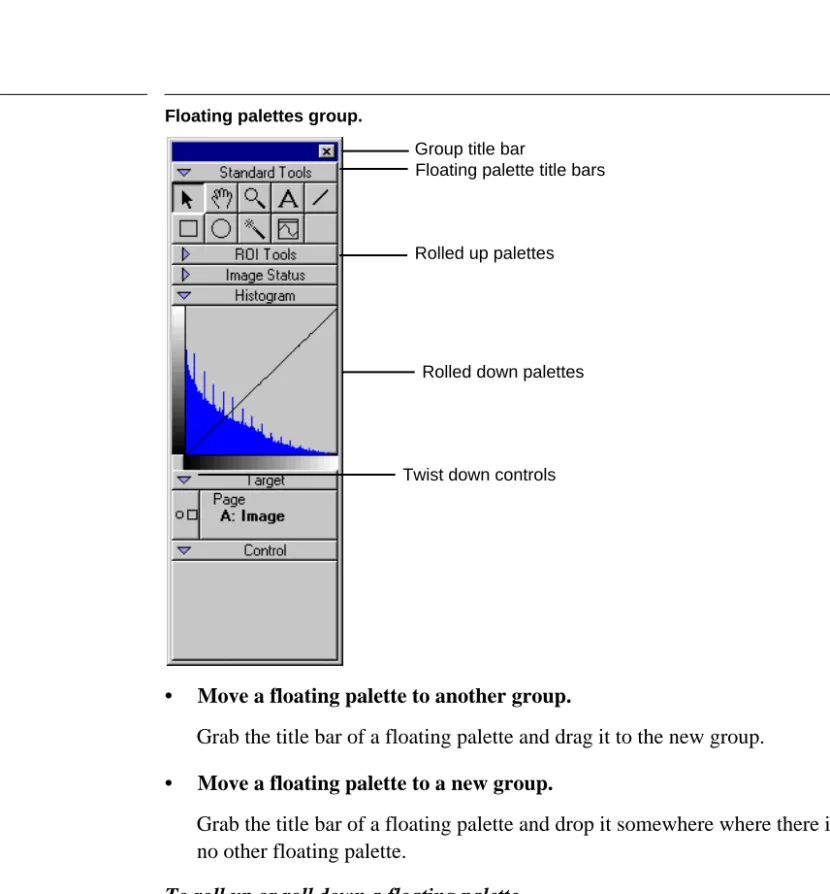
You can configure the layout of floating palettes that is most suitable for your work. You can group sets of the floating palettes together and you can “roll-up” a particular floating palette in order to reduce the space it takes on the screen. See Figure 2-6.
Some of the older DigitalMicrograph acquisition plug-ins will present a floating palette that cannot be grouped with other floating palettes.
DigitalMicrograph will remember the positions and groupings of all of your floating palettes from session to session. If you exit DigitalMicrograph and launch it again later, the floating palettes and groups will return to the same con-figuration.
To open a new floating palette
DigitalMicrograph lists all of the floating palettes in the FLOATING WINDOWSmenu.
• Select the desired floating palette from the FLOATING WINDOWS submenu under the WINDOW menu.
DigitalMicrograph will add the new floating palette to the group at the top-left of the main screen. If no group exists there, DigitalMicrograph will cre-ate a new group.
To move floating palettes
Floating palettes can be moved in the following ways: • Move an entire group of floating palettes.
Grab the group title bar and drag it to a new location. • Move a floating palette above another within a group.
Grab the title bar of a floating palette and drag and drop it on the title bar of another to place it above the existing palette.
• Move a floating palette below another within a group.
Grab the title bar of a floating palette and drag and drop it on the contents of another to place it below the existing palette.
Using Floating Palettes
Figure 2-6 Floating palettes group.
• Move a floating palette to another group.
Grab the title bar of a floating palette and drag it to the new group. • Move a floating palette to a new group.
Grab the title bar of a floating palette and drop it somewhere where there is no other floating palette.
To roll up or roll down a floating palette
DigitalMicrograph allows you to roll up and roll down floating palettes to save screen space and get unused controls out of your way.
• Click on the Twist Down control to roll up or roll down a floating pal-ette.
To close a floating palette
You can close floating palettes completely. • Close an entire group of floating palettes.
Twist down controls Rolled up palettes
Rolled down palettes Group title bar
Setting Preferences and Information
DigitalMicrograph 3.4 User’s Guide 2-15
• Close a specific floating palette.
Drag the floating palette to a new group and close the new group.
2.9 Setting Preferences and Information
Preferences help DigitalMicrograph to tailor its operation to your specific needs.
The GLOBAL INFO dialog allows you to choose preferences. This dialog is divided into a list of panels along the left side, and the selected panel on the right side. To switch to a different panel, select a different panel from the list on the left. See Figure 2-7.
To enter scale marker preferences
DigitalMicrograph can automatically add a scale marker to images that you acquire from acquisition devices.
1. Choose GLOBAL INFO from the FILE menu.
The Global Info dialog will appear.
2. Select Data Bar on the left side of the dialog box.
The Data Bar panel will appear in the right side of the dialog box.
Setting Preferences and Information
3. Enter the information in the right portion of the dialog box.
4. Click OK.
Switching to a different panel will automatically save your choices. To enter Auto-save preferences
DigitalMicrograph can automatically save a series of images to a sequentially numbered set of files. This is useful during acquisition or during a long process-ing sequence.
1. Choose GLOBAL INFO from the FILE menu.
The Global Info dialog will appear.
2. Select Auto-save on the left side of the dialog box.
The Auto-save panel will appear in the right side of the dialog box. See Figure 2-8.
Figure 2-8 Global Info—Auto-save.
Data Bar Check here if you want a scale marker automatically placed on your acquired images.
Setting Preferences and Information
DigitalMicrograph 3.4 User’s Guide 2-17
3. Enter the information in the right portion of the dialog box.
4. Click OK.
Switching to a different panel will automatically save your choices. To enter page measurement unit preferences
DigitalMicrograph can display image measurements in English or metric units. 1. Choose GLOBAL INFO from the FILE menu.
The Global Info dialog will appear.
2. Select Page on the left side of the dialog box.
The Page panel will appear in the right side of the dialog box.
Figure 2-9 Global Info—Page.
3. Enter the information in the right portion of the dialog box.
4. Click OK.
Switching to a different panel will automatically save your choices.
Series Name Enter the series name here. The files will be saved under the file name ImageSeries.# where ImageSeries is the value in this field and # is the series index.
Series Index Enter next index to be used for saving.
Select Folder Click here to select the folder in which to save your images.
Setting Preferences and Information
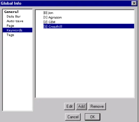
To edit keywords
DigitalMicrograph can keep track of a list of keywords that will be attached to all saved images.
1. Choose GLOBAL INFO from the FILE menu.
The Global Info dialog will appear.
2. Select Keywords on the left side of the dialog box.
The Keywords panel will appear in the right side of the dialog box.
Figure 2-10 Global Info—Keywords.
3. Enter the information in the right portion of the dialog box.
4. Click OK.
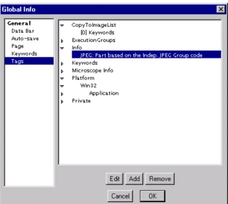
Switching to a different panel will automatically save your choices. To edit tags
DigitalMicrograph keeps an internal database of assorted information such as user preferences, algorithm options, and other data vital to the operation of Dig-italMicrograph. You can directly edit this information.
A list of keywords is displayed.
Edit Click this button to edit the selected keyword.
Add Click this button to add a new keyword.
Setting Preferences and Information
DigitalMicrograph 3.4 User’s Guide 2-19
Editing tags is an advanced use of DigitalMicrograph and should, in general, not be performed unless you have explicit instructions on how to do so. It is possible to make DigitalMicrograph unlaunchable by editing tags.
1. Choose GLOBAL INFO from the FILE menu. The Global Info dialog will appear.
2. Select Tags on the left side of the dialog box.
The Tags panel will appear in the right side of the dialog box.
Figure 2-11 Global Info—Tags.
3. Enter the information in the right portion of the dialog box.
4. Click OK.
Switching to a different panel will automatically save your choices. A list of tags is displayed. You can use the twist-down controls to open up groups and lists of tags.
Edit Click this button to edit the selected tag.
Add Click this button to add a new tag.
DigitalMicrograph 3.4 User’s Guide 3-1
3 Images
Manipulating, acquiring, displaying, and storing images is the primary purpose of DigitalMicrograph. This chapter gives a quick introduction to the basic con-cepts associated with images.
3.1 About Images
DigitalMicrograph deals primarily with images. Each image is represented by a set of numbers called pixels. For instance, an image that is 200 pixels wide and 300 pixels tall is represented by 200 x 300 = 60,000 numbers. These numbers are arranged to match the dimensions of the image, i.e. into 300 rows of 200 numbers each (an array).
Since images are represented by so many numbers, they take up large amounts of memory. Each image will take up enough memory to store its numbers plus enough memory to display the image.
DigitalMicrograph also displays images. Images can be displayed in a number of ways, e.g. similar to a photograph, in a spreadsheet, etc. Images can also be calibrated so that each pixel’s value and location has a physical meaning. About Data Types
Each pixel in an image is represented by one or more numbers. This representa-tion is called the data type. Each data type has specific characteristics such as amount of memory used, precision, and ability to represent different types of numbers.
DigitalMicrograph supports the following five major data types:
• Binary
About Images
• Integer
Pixels represented by whole, integer numbers. Numbers can be signed (posi-tive and nega(posi-tive) or unsigned (posi(posi-tive only). Each pixel can take one, two, or four bytes of memory.
• Real
Pixels represented by real numbers. Each pixel can take four or eight bytes of memory.
• Complex
Pixels represented by two real numbers, the real and imaginary components. Each real number can be represented by either four or eight bytes of memory. Thus, each complex pixel can be represented by either eight or sixteen bytes of memory for each pixel.
• RGB
Pixels represented by four unsigned one-byte integers, the red, green, blue, and alpha channels.
About Memory Usage
The memory used by a particular image is dependent on the size of the image and the data type of the image. The more bytes per pixel of the image, the more memory used.
Total memory used by an image is calculated by multiplying the dimensions of the image by the bytes per pixel of the image. The kilobytes of memory (kB) or megabytes of memory (MB) are found by dividing the total number of bytes by 1024 for kilobytes and 1,048,576 for megabytes.
For example, a 700 x 800 real data image will take up 700 x 800 x 4 bytes of memory, or 2,240,000 bytes of memory. This is equivalent to 2187.5 KB and 2.14 MBof memory.
In addition, each image will use additional memory when displayed.
The amount of memory used by each image and its display is listed under the
WINDOWS menu. Furthermore, the amount of free memory available for use in images is listed in the WINDOWS menu under FREE MEMORY.
About Display Types
Since an image is just a set of numbers, there are many ways to visualize the image. Images with certain data types can only be displayed by image display methods suitable for that data type. Some display methods make use of specific information about the data they are displaying.
About Images
DigitalMicrograph 3.4 User’s Guide 3-3
DigitalMicrograph generally splits the data types into those that can ultimately be represented by a single number, and those that can’t. All of the binary, inte-ger, and real data can be trivially represented by a single number. Complex data can be converted to a single number if you specify how you want to convert it (by taking the magnitude or phase, for instance). RGB images, on the other hand, cannot be represented by a single number.
Images that can be represented by single numbers can be displayed using raster, surface model, surface plot, and line plot displays. Images that have RGB pixels can be displayed using RGB displays. Spreadsheet displays can display images of any type.
About Complex Data
Some displays will only display images with pixels represented as single num-bers. Complex data, though, has two real number components, the real and imaginary portion. To display complex data, DigitalMicrograph converts a complex number to a real number through one of five methods:
REAL COMPONENT. Takes the real portion of the complex number.
IMAGINARY COMPONENT. Takes the imaginary portion of the complex number.
MODULUS. Takes the modulus or magnitude of the complex number.
LOGOFMODULUS. Takes the natural logarithm of the modulus of the complex number.
PHASE. Takes the phase of the complex number. About RGB Data
The RGB display will only display images represented by RGB pixels. This is known as direct display of the data. DigitalMicrograph only displays what is known as 24-bit RGB data, which consists of three 8-bit components (red, green, and blue) and an additional 8-bit component called the alpha channel. This channel exists to optimize speed of retrieving data stored in memory for data stored in 4-byte chunks can be accessed faster than that stored in 3-byte chunks. The alpha channel of each pixel is currently not used by DigitalMicro-graph.
About Calibrations
An image is simply a set of numbers arranged into rows and columns. Digi-talMicrograph allows you to calibrate an image so that the row and column cor-respond to a physical distance.
For example, if you have an image that is 200 x 300 pixels, it may represent a physical sample that is 25 x 37.5 nm. DigitalMicrograph could treat each pixel as if it were 25 nm /200 pixels = 0.125NMwide. Then, whenever
DigitalMicro-Setting Image information
graph reported measurements, or positions of pixels, it would report them in NANOMETERSinstead of pixels.
Furthermore, in applications such as Atomic Force Microscopy, the intensity of a particular pixel can be calibrated to represent a physical value.
For example, if you have an image with intensity values in the range of 200 to 1400, these values may actually represent the physical height of the sample ranging from 30 NM to 210 NM. DigitalMicrograph could treat each pixel value to represent 30 NM/200 = 0.15 NM per intensity unit. Then, whenever DigitalMicro-graph reported the value of a pixel, it would report it in NANOMETERS instead of a raw number.
About Image Status
DigitalMicrograph provides a convenient way to view the type of an image, the position of the cursor within an image, and the intensity value under the cursor. All measurements will be displayed as calibrated numbers if calibrations were performed.
Figure 3-1 Image Status.
The Image Status palette tells you which image the cursor is on (Image A in fig-ure above), the data type (Real 4), the size of the image (256 x 256 pixels), the x and y positions of the cursor (146,155), and the intensity value at that position (0.931697).
The particular information displayed in this palette will depend on the data type, calibrations, and display type of the image the cursor is on.
3.2 Setting Image information
DigitalMicrograph keeps track of many pieces of information regarding an image such as calibrations, image size, keywords, and more. You can view and enter information using the Object Info dialog.
Setting Image information
DigitalMicrograph 3.4 User’s Guide 3-5
Like the Global Info dialog, the Object Info dialog is divided into a list of panels along the left side and the selected panel on the right side. To switch to a differ-ent panel, select a differdiffer-ent panel from the list on the left.
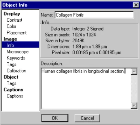
Figure 3-2 Object Info—Image–Info.
To enter or see information about an image You can see detailed information about an image.
1. If you are viewing the image document in page mode, select the image you want to inspect.
2. Choose IMAGE DISPLAY under the OBJECT menu. The Object Info dialog will appear.
3. Select IMAGE->INFO on the left side of the dialog box.
The Image Info panel will appear in the right side of the dialog box. 4. Enter the name of the image and any additional image description.
The following information will automatically be displayed:
Data Type The data type of the image.
Size in Pixels The size of the image in pixels.
Size in Bytes The size of the image in bytes.
Dimensions The dimensions of the image as calibrated.
Setting Image information
5. Click OK.
Switching to a different panel will automatically save your choices. To change the name of an image
You can change the name of the image document in which the image is con-tained.
1. If you are viewing the image document in page mode, select the image of which you want to change the name.
2. Choose IMAGE DISPLAY under the OBJECT menu. The Object Info dialog will appear.
3. Select IMAGE->INFO on the left side of the dialog box. 4. Enter the name of the image in the name field. 5. Click OK.
To enter a description of an image
You can enter a description of an image that will be stored with the image. 1. Select the image for which you want to enter a description.
2. Choose IMAGE DISPLAYunder the OBJECT menu. The Object Info dialog will appear.
3. Select IMAGE->INFO on the left side of the dialog box.
4. Enter the description of the image in the description field. The description can be up to 32 KB in length.
5. Click OK.
To edit an image’s keywords
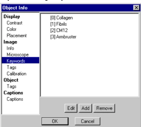
DigitalMicrograph keeps track of a list of keywords that will be attached to all saved image documents. These keywords will be visible in supported image database applications.
1. If you are viewing the image document in page mode, select the image for which you want to edit its keywords.
2. Choose IMAGE DISPLAY under the OBJECT menu.
Setting Image information
DigitalMicrograph 3.4 User’s Guide 3-7
The Keywords panel will appear in the right side of the dialog box.
Figure 3-3 Object Info— Image–Keywords.
4. Enter the information in the right portion of the dialog box.
5. Click OK.
Switching to a different panel will automatically save your choices. To edit an image’s tags
DigitalMicrograph keeps an internal database of assorted information such as user preferences, algorithm options, and other data vital to the operation of Dig-italMicrograph. Some of this information is stored with an image. You can directly edit this information.
Editing tags is a very advanced use of DigitalMicrograph and should, in gen-eral, not be performed unless you have explicit instructions on how to do so. It is possible to make images unloadable by editing tags.
A list of keywords is displayed.
Edit Click this button to edit the selected keyword.
Add Click this button to add a new keyword.
Setting Image information
1. If you are viewing the image document in page mode, select the image for which you want to edit its tags.
2. Choose IMAGE DISPLAY under the OBJECT menu.
The Object Info dialog will appear.
3. Select IMAGE->TAGS on the left side of the dialog box.
The Tags panel will appear in the right side of the dialog box.
Figure 3-4 Object Info— Image–Tags.
4. Enter the information in the right portion of the dialog box.
5. Click OK.
Switching to a different panel will automatically save your choices. A list of tags is displayed. You can use the twist-down controls to open up groups and lists of tags.
Edit Click this button to edit the selected tag.
Add Click this button to add a new tag.
Remove Click here to remove the selected tag.
Update Global Info Click here to copy any tags in Global Info that are set up to be copied to images to the image.
DigitalMicrograph 3.4 User’s Guide 4-1
4 Image Display
DigitalMicrograph deals primarily with images. Images come in many configu-rations, sizes, and data types. DigitalMicrograph provides several methods of displaying the data in an image. Some of the methods are appropriate for only certain types of image data, while others work with any type of image data.
4.1 Visualizing Images
The method that DigitalMicrograph uses to display an image is called the image display type. DigitalMicrograph provides several image display types.
• Raster image display.
• Surface Plot image display.
• RGB image display.
• Line Plot image display.
• Spreadsheet image display.
• Surface Model image display (MacOS only).
Each of these image display types has many options associated with it. Further-more, some of the image display types (such as RGB) are only appropriate for certain types of data (RGB data only).
To change image display type
You can change how an image is displayed.
1. If you are viewing the image document in page mode, select the image of which you want to change the display type.
Using Raster Image Displays
2. Choose a new image display type in the DISPLAY TYPE submenu under the
OBJECT menu.
The check mark indicates the display type of the selected image.
Only the image display types that are valid for the selected image will be enabled.
In Figure 4-1, the RGB display type is not valid for the selected image. Upon selection of a new display type, DigitalMicrograph will change the image display type of the image to the newly selected one. Any specific information you configured for the old image display will be lost.
Figure 4-1 Display Type submenu.
To create a new image from the display
Sometimes it will be convenient to generate a new image representing every-thing that is displayed in the image window. If you have multiple images, objects, and annotations on the page, you can consolidate all of these into a sin-gle new image. However, the individual components on the page will not be
editable in the new image display, which will be rendered at screen resolution (roughly 72 pixels/in.).
1. Select the image document of which you want to create a display. 2. Make the display look how you want it to look in the new image.
You can place the image document in page or image mode to view either all of the images or only a single image.
3. Choose CREATE IMAGEFROM DISPLAY under the OBJECT menu.
A new image document will appear that contains a single image represent-ing the original image document (as it appeared on the screen and at screen resolution).
4.2 Using Raster Image Displays
Using Raster Image Displays
DigitalMicrograph 3.4 User’s Guide 4-3
displayed with Raster image displays. Each pixel in the image is displayed as a greyscale value or an RGB color determined by indexing the intensity into a color table (see “Using Image Displays with Color Transformations” on page 10 of this chapter).
Figure 4-2 Raster image display.
To add/remove captions
DigitalMicrograph can display captions indicating the calibration of the image (see Figure 4-3). Captions are off by default.
1. If you are viewing the image document in page mode, select the image to which you want to add or from which you want to remove captions. 2. Choose IMAGE DISPLAY under the OBJECT menu.
The Object Info dialog will appear.
3. Select CAPTIONS->CAPTIONS on the left side of the dialog box.
The Captions panel will appear in the right side of the dialog box. See Figure 4-4.
4. Click on the CAPTION check box to enable or disable captions.
See Figure 4-3 for an image display with Captions on.
5. Click on the Save Defaults button to indicate that you always want cap-tions turned on or off for all new images.
Using Raster Image Displays
Figure 4-3 Raster image display with Captions.
Using Surface Model Image Displays
DigitalMicrograph 3.4 User’s Guide 4-5
To see a value at a particular image position
DigitalMicrograph will display the position of the cursor within the image and the intensity of the pixel at that position in the Image Status palette. The values will be displayed in calibrated units if the image is calibrated.
• Move the cursor over the Raster image display to see the pixel position and value in the Image Status palette.
Figure 4-5 Image Status for Raster image display.
4.3 Using Surface Model Image Displays
Surface Model image display is only available on the MacOS version of Digi-talMicrograph.
Using Surface Model Image Displays
The Surface Model image display is displayed as a three-dimensional surface that you can rotate, scale, and move closer to or further from. The intensity of each pixel in the image is correlated to a greyscale value or an RGB color deter-mined by indexing the intensity into a color table (see “Using Image Displays with Color Transformations” on page 10 of this chapter).
Your computer must have QuickDraw 3D installed in order to use Surface Model image displays.
To adjust 3D rendering
You can adjust certain parameters of the 3D rendering process to either speed things up or improve the quality of the rendering.
1. If you are viewing your image document in page mode, select the image for which you want to adjust rendering parameters.
2. Choose IMAGE DISPLAYunder the OBJECT menu. The Object Info dialog will appear.
3. Select DISPLAY->3D MODELon the left side of the dialog box.
The 3D Model panel will appear in the right side of the dialog box.
Using Surface Model Image Displays
DigitalMicrograph 3.4 User’s Guide 4-7
4. Enter the DYNAMIC SIZE for rendering.
Dynamic Size is the rendering resolution used while rotating, scaling, zoom-ing, or otherwise manipulating the surface model. A smaller rendering value is appropriate here in order to speed up these processes.
5. Check DYNAMIC SHADED as desired.
While rotating, scaling, zooming, or otherwise manipulating the surface model, you can choose to have it shaded or just be a wireframe model. 6. Enter the STATIC SIZE for rendering.
Static Size is the rendering resolution when the surface model is not being edited. Larger values look smoother, but will slow down the rendering pro-cess. This value should never be larger than the smaller of the width or the height.
7. Check STATIC SHADED as desired.
This controls whether the model, when not being edited, is shaded or not. 8. Check WALLS ON as desired.
This controls whether walls are drawn around the surface model. Walls can improve the perception of the surface model.
9. Click OK.
The surface model will be changed according to your preferences. To rotate the surface model
You can rotate the surface model in space using the 3D ROTATE tool. This tool is located in the 3D TOOLS palette.
Figure 4-8 Surface Model 3D tools.
• Click and drag in the image with the 3D Rotate tool.
Move the cursor left and right and up and down to rotate the model left and right and forward and backward.
3D Rotate tool 3D Scale tool 3D Distance tool
Using Surface Plot Image Displays
To move closer or farther from the surface model
You can move closer to or farther from the surface model using the 3D Distance tool. This tool is located in the 3D Tools palette.
• Click and drag in the image with the 3D DISTANCE tool.
Move the cursor up to move closer and down to move farther away. To change the height of the surface model
You can change the height of the surface model using the 3D Scale tool. This tool is located in the 3D Tools palette.
• Click and drag in the image with the 3D SCALE tool.
Move the cursor up to increase the model’s height and down to decrease it.
4.4 Using Surface Plot Image Displays
The Surface Plot image display is displayed as a three-dimensional surface.
Figure 4-9 Surface Plot image display.
Using Surface Plot Image Displays
DigitalMicrograph 3.4 User’s Guide 4-9
You can change the view of the surface plot slightly and you can choose whether the surface plot is shaded or not. The intensity of each pixel in the image is displayed as a greyscale value or an RGB color determined by index-ing the intensity into a color table (see “Usindex-ing Image Displays with Color Transformations” on page 10).
To change the view of a surface plot You can change the view of the surface plot.
• Change the view of the surface plot by dragging one of the three adjust-ment handles.
Your view of the data will always be from the same side. To turn Shading on or off
You can disable or enable Shading on the surface plot. The surface plot will be rendered slightly faster if Shading is disabled.
1. If you are viewing the image document in page mode, select the image for which you want to adjust Shading.
2. Choose IMAGE DISPLAYunder the OBJECT menu.
The Object Info dialog will appear.