Sharif University of Technology
Scientia IranicaTransactions B: Mechanical Engineering www.scientiairanica.com
Computational investigation into vortex breakdown
over a pitching delta wing at supersonic speeds
M. Hadidoolabi and H. Ansarian
Department of Aerospace Engineering, Malek Ashtar University of Technology, Lavizan, Tehran, Iran. Received 14 February 2016; received in revised form 10 October 2016; accepted 29 October 2016
KEYWORDS Delta wing; Pitching oscillation; Vortex breakdown; Supersonic ow; Aerodynamic coecients
Abstract.Vortex breakdown in compressible ows over a 60-degree sweep delta wing with a sharp leading edge undergoing pitching oscillations is computationally studied. Emphasis in this study is on possible supersonic vortex breakdown for pitching motion of a delta wing, as well as behavior of the aerodynamic characteristics during a cycle. Unstructured grid, k !SST turbulence model, and dual-time implicit time integration are used. Accurate simulations are performed for various Mach numbers and mean angles of attack to cover dierent ow structures and phenomena associated with them. Variations of ow structure around the wing and hysteresis loops associated with lift coecient and vortex breakdown location during a pitching cycle are investigated. The trends with Mach number, mean angle of attack, amplitude of pitching, and pitching frequency are illustrated.
© 2017 Sharif University of Technology. All rights reserved.
1. Introduction
Delta wings are used in many aircrafts, which y at supersonic speeds. Airplanes and space planes with delta wing often y at high angles of attack, especially in take-o or landing phases, where their aerodynamic performance at low speeds is weak. Moreover, ying at high angles of attack even at transonic and supersonic regimes can be expected from future space planes in the reentry phase. As the maneuverability of such aircraft enhances, the comprehension of the nature of unsteady ows around delta wings becomes more important. In particular, if computational models are to be developed for time-dependent motions of the aircraft or its aero-dynamic surfaces, it is necessary to study the features such as vortex breakdown and vortex-shock patterns on delta wings and the associated physical mechanisms.
*. Corresponding author.
E-mail addresses: [email protected] (M. Hadidoolabi); [email protected] (H. Ansarian) doi: 10.24200/sci.2017.4246
It is well known that in the steady ight of a delta wing, a shear layer is separated from the leading edge, which produces two counter-rotating vortices on the leeside of the wing. This results in production of large suction peaks and, thereby, generation of lift. Two much smaller vortices with opposite sense of rotation relative to primary vortices, i.e. the secondary vortices, are also formed in certain ow conditions. At suciently high angles of attack, the leading edge vortices above a delta wing undergo a vigorous form of ow discontinuity known as vortex breakdown. This phenomenon is characterized by vortex core ination, internal axial ow stagnation, and substantial uctua-tions in ow variables downstream.
The sudden onset of vortex breakdown as well as the consequent lags and hysteresis, which appear in aerodynamic loads, can have severe impacts on stability and control of high-performance aircraft and may lead to the reduction in its operational envelope. More-over, the coherent uctuations characteristic of vortex breakdown may assist undesirable uid/structure in-teractions among aircraft components intersecting the vortex path.
Vortex breakdown on stationary delta wings at incompressible regime has been the focus of many eorts. Gursul et al. [1,2] presented extensive reviews of the steady and unsteady aerodynamics of delta wings ying at low speeds.
The unsteady ow structure on a delta wing undergoing maneuver has received less attention. Such research is motivated by the need to enhance the maneuver capabilities of current and future combat airplanes, missiles, and spacecraft. When a delta wing is subjected to pitching, plunging, or any other type of unsteady motion, a time lag is seen in the response of the vortex ow. This usually results in a temporary delay in vortex formation at low angles of attack or temporary delay in vortex breakdown at higher angles of attack. For delta wings subjected to periodic motions, a hysteresis develops in the ow characteristics relative to the stationary wing, which may increase with motion frequency. Using these unsteady eects, a high-performance aircraft can be able to perform certain maneuvers more quickly and eciently.
Rockwell [3] and Visbal [4] reviewed the unsteady aspects of ow structures and vortex breakdown on delta wings. For sinusoidal oscillation of a delta wing with highly reduced frequency, Atta and Rockwell [5] observed the existence of vortex core over only a fraction of the motion cycle, and occurrence of the maximum vortex breakdown position near the maxi-mum angle of attack, instead of at the minimaxi-mum angle of attack, which is expected from the quasi-steady assumptions. LeMay et al. [6] studied the response of breakdown position on a delta wing to a harmonic pitching motion and the eect of reduced frequency. By performing unsteady pressure measurements on a pitching delta wing, Gursul and Yang [7], based on the suggestion of Gursul and Ho [8] that vortex breakdown over delta wings in unsteady ow was caused by the external pressure gradient, showed that the phase lag of the vortex breakdown position on the wing might be related to the adverse pressure gradient and its variations on the wing surface. Lin and Rockwell [9] dened the region of vortex breakdown in terms of patterns of azimuthal vorticity, as well as critical points of the sectional topology. Jones et al. [10] studied the relation between the appearance of negative azimuthal vorticity and the onset of vortex breakdown over a delta wing using computational simulations of ow over the static and pitching delta wing. Goruney and Rockwell [11] investigated the near-surface ow structure and topology on a delta wing of moderate sweep angle using a technique of high-image-density digital particle image velocimetry. They studied the time evolution of the surface topology during relaxation of the ow after termination of a pitching maneuver for a wide range of pitch rates. Jian et al [12] used and
Improved Delayed Detached Eddy Simulation (IDDES) method based on the k !SST turbulence model to predict the unsteady vortex breakdown past an 80=65
double-delta wing. They analyzed the uctuations of mean lift, drag, pitching moment, pressure coecients, and breakdown locations.
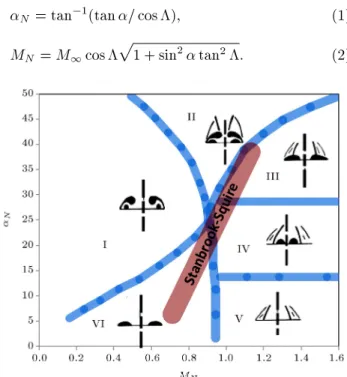
Most studies of unsteady vortical ow structure on oscillating delta wings have been done for incom-pressible ows or for ows with very low free-stream Mach number. As a result, little is known about the onset and transient behavior of breakdown on a pitching delta wing at higher Mach numbers, especially at supersonic speeds. When ying with much higher speeds, ow becomes more complicated since shock waves appear in the ow, which interact with vortices. At supersonic velocities, there may be various ow regimes on the leeward side of delta wings, which dier by the numbers and positions of streamwise vortices, internal shock waves, and other features of the ow. The earliest eort to understand supersonic ow pattern over delta wings for various wing geometries and various ow conditions appeared in the work by Stanbrook and Squire [13]. They examined all the experimental data available and proposed a classica-tion for the ow patterns based on the component of Mach number normal to the leading edge, MN, and
the component of angle of attack normal to the leading edge, N. They introduced two types of ows, namely,
attached ow and separated ow, at the leading edge. These two types were separated by a boundary line near MN = 1, which was called the Stanbrook-Squire
boundary (Figure 1). Parameters N and MN were
calculated as follows:
N = tan 1(tan = cos ); (1)
MN = M1cos
p
1 + sin2 tan2: (2)
Miller and Wood [14] experimentally investigated the ow patterns over delta wings with various sweep angles using several visualization methods. They introduced six types of ow patterns based on N and
MN:
(I) Classical vortex;
(II) Vortex with shock;
(III) Separation bubble with shock;
(IV) Shock-induced separation;
(V) Shock with no separation;
(VI) Separation bubble with no shock.
These patterns are shown in Figure 1. Szodruch and Peake [15] proposed a similar classication for delta wings with more thickness than those studied by Miller and Wood. Seshadri and Narayan [16], Brodetsky et al. [17], and Brodetsky and Shevchenko [18] proposed similar classications by examining ow elds in more detail. Imai et al. [19] conducted computational simulations of ow eld over a 65 sweep delta wing
and investigated the ow mechanism behind the ow classication at high angles of attack in transonic and supersonic regimes. Oyama et al. [20] performed wind tunnel experiments to examine the eect of Mach number on ow structure over a delta wing with blunt leading edges in supersonic and high angle of attack regions.
Literature review shows that there has not been signicant research, either computational or experi-mental, performed for steady or unsteady aspects of supersonic vortex breakdown over delta wings. In this study, ow elds over a 60 pitching delta wing with
sharp leading edge at various mean angles of attack, from subsonic to supersonic regimes, are computa-tionally simulated and the results are analyzed. The objective of the present study is to investigate when the vortex breakdown occurs in supersonic ow and how its location along the wing chord varies during a pitching cycle. Also, the corresponding aerodynamic characteristics of hysteresis loops are studied. The eects of frequency, Mach number, pitching amplitude, and mean angle of attack are investigated.
2. Methodologies
2.1. Computational methods
Three-dimensional unsteady compressible Navier-Stokes equations are solved as the governing equations using a valid CFD code. Numerical uxes for the convective terms are computed using the Roe scheme, and the upwind MUSCL algorithm is applied to extend the spatial accuracy to 2nd order based on the primitive variables. The viscous uxes are computed using the 2nd order central dierencing. The ow eld is
assumed to be fully turbulent, and the two-equation k !SST turbulence model is applied. Dierent versions of k ! turbulent model have been found to be appropriate for capturing vortex ow over delta wings by several researchers [21-24]. Schiavetta et al. [22] compared the Detached Eddy Simulation (DES) and Unsteady Reynolds-Averaged Navier-Stokes (URANS) turbulence modeling methods for prediction of un-steady vortical ows over delta wings. They con-cluded that URANS turbulence models were able to predict the dominant features of the low-frequency phenomenon present in the vortex system. An implicit dual-time algorithm was applied for the unsteady time integration. Density was calculated by ideal gas law and viscosity by Sutherland's law.
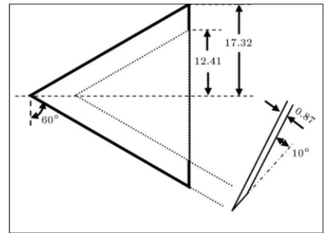
2.2. Model geometry and grid
The model geometry is illustrated in Figure 2. As shown in the gure, the analyzed delta wing has leading-edge sweep angle of 60. The upper surface
is at and the leading edge is sharp (10angle normal
to leading edge located on lower surface) to minimize the eect of leading edge shape on the ow eld. Wing thickness ratio is 0.03 based on the root chord length. The model is geometrically similar to that of Miller and Wood [14]. There is no sideslip (yaw) angle, thus the ow eld must be considered to be symmetric on the center line of the wing. Therefore, only half of the wing is covered by the computational domain. This ap-proach neglects the potential ow asymmetry over the wing, but has been found to exhibit enough accuracy for low to moderate angles of attack [10,22,23,25]. The simulations were performed on an unstructured grid (Figure 3), which approximately had 7:0 106 cells
and was obtained after excessive simulation for grid independence study.
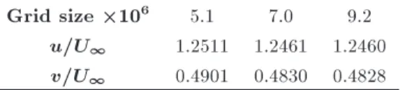
Since the objective of this study was to simulate the ow structure accurately, grid study was performed by checking the convergence of the numeric values of ow eld variables in several ow eld points for several steady ow conditions. An example is shown in Table 1
Figure 3. Computational grid.
Table 1. Axial and tangential velocity components in an arbitrary point for various grid sizes.
Grid size 106 5.1 7.0 9.2
u=U1 1.2511 1.2461 1.2460
v=U1 0.4901 0.4830 0.4828
for the average non-dimensional axial and tangential velocities in a selected point near the vortex core. This point was located in a crossow plane at 30% chordwise station, for the ow with Mach number of 1.2 and angle of attack of 20.
The grid had a rst wall spacing of 1 < y+ < 6,
which was appropriate for the turbulent model used. The grid was rened within the vortex core region to improve the grid quality for capturing the vortices well. The upper and lower surfaces of the wing were specied as solid wall with no-slip boundary conditions. Symmetry boundary condition was applied for the symmetry plane. The remaining domain was a hemisphere with diagonal of 15 root chord length and was specied as pressure fareld. The converged steady-state solution was used as the initial condition. 2.3. Flow conditions
To examine the possible breakdown behaviors in dier-ent supersonic ow structures over the delta wing, the ow conditions in this study were chosen to cover the classication chart of Miller and Wood [14]. The ow and pitch oscillation conditions numerically simulated in the present work are shown in Table 2. Figure 4 shows the ow conditions plotted over the classication chart of Miller and Wood. The large symbols in the gure denote the mean state and the small symbols denote the angle of attack extremes. Small and large arrows represent the oscillations with amplitudes of 4
and 8, respectively. Free-stream Mach numbers are
0.4, 0.8, 1.2, and 2.0. For the subsonic Mach numbers, only one condition (mean angle of 20, amplitude of
4, and frequency of 10 Hz) is selected. For the
Table 2. Flow conditions.
M1 0
(deg) (deg) f (Hz) k
0.4 20 4 10 0.076
0.8 20 4 10 0.04
1.2 8 4,8 5,10,50 0.013,0.027,0.133 1.2 20 4,8 5,10,50 0.013,0.027,0.133 1.2 30 4,8 5,10,50 0.013,0.027,0.133 2 8 4,8 5,10,50 0.008,0.016,0.08 2 20 4,8 5,10,50 0.008,0.016,0.08 2 30 4,8 5,10,50 0.008,0.016,0.08
2 40 4 10 0.016
Figure 4. Flow conditions.
supersonic Mach numbers, three mean angles of attack, two amplitudes, and three frequencies of motion, plus an additional condition for M1 = 2, are selected
to study the eect of each parameter in supersonic conditions. For each condition, the Reynolds number based on the wing root-chord length is 1:3 106,
similar to the experiments of Miller and Wood [14]. Continuous sinusoidal pitching is performed and the pitching axis is located half maximum thickness below the half root chord location. The wing motion is described as follows:
= 0+ sin(!t + ): (3)
It is important to note that because of large magnitudes of free-stream speed in supersonic regime, reduced frequency, k = fc=U1, has not a large value even
at high frequencies.
3. Results and discussions
An extensive post-processing eort was made to under-stand the physical phenomena occurring in the ow.
Among the 39 cases mentioned above, some conditions in which vortex breakdown occurs are presented here. 3.1. Flow patterns
Before we investigate the vortex breakdown phenomena over the pitching delta wing, it is useful to show the numerical simulation results of some ow pat-terns introduced by classication chart of Miller and Wood [14]. Details of these vortical ow structures and how they change during a pitching motion are not the subject of this paper. Instead, the breakdown behaviors associated with them are discussed in the next section. The authors [24] have simulated the various crossow patterns over the stationary and pitching delta wing and have veried their results with experimental data.
Figure 5 shows local Mach number contour map and total pressure contour lines in the crossow plane at 30% chordwise station for the ow with free-stream Mach number of 0.8 and angle of attack of 20. This
type of ow is classied into \classical vortex (type (I))" characterized by the primary and secondary vor-tices with no shock waves. However, a crossow shock wave arises below the primary vortex core. Adverse pressure gradient due to this shock wave enhances the secondary ow separation. Flow with Mach number of 1.2 and angle of attack of 20 would have a similar
pattern as it is indicated in the chart. Figure 6 shows the similar map for ow with Mach number of 1.2 and angle of attack of 30. The structure of
ow with these conditions is \vortex with shock (type (II))". The spanwise ow acceleration induced by the primary vortex leads to the appearance of the shock wave over the primary vortex, which is a weak oblique shock in this condition. This shock decelerates ow toward the wing root and changes the ow direction. In Figure 7, the crossow pattern for the ow with Mach number of 2 and angle of attack of 40 is shown.
The \vortex with shock" pattern in this condition is
Figure 5. Local Mach number contour map and total pressure contour lines in the crossow plane at 30% chordwise station for ow with M1= 0:8, and = 20.
Figure 6. Local Mach number contour map and total pressure contour lines in the crossow plane at 30% chordwise station for ow with M1= 1:2, and = 30.
Figure 7. Local Mach number contour map and total pressure contour lines in the crossow plane at 30% chordwise station for ow with M1= 2:0, and = 40.
accompanied by a horizontal shock wave between the pair of primary vortices. Also, it can be seen in the gure that secondary separation has experienced the breakdown although the primary vortex still exists. 3.2. Vortex breakdown
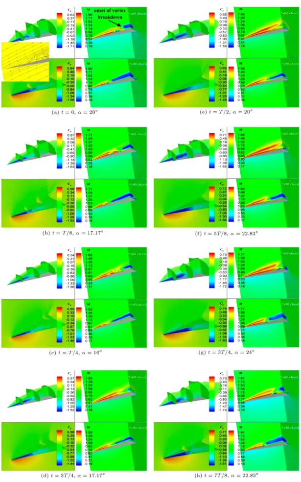
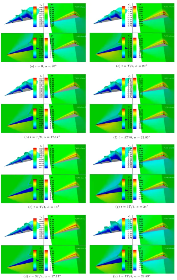
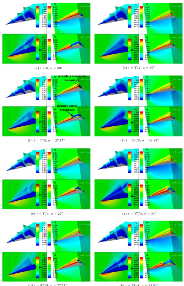
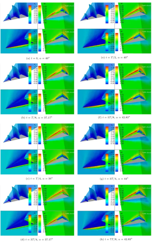
Figures 8 to 11 show the static pressure coecient and Mach number contours over the leeward side of the wing and the ow eld around it for a pitching cycle at four ow conditions. At the left-hand side of these gures are shown the pressure coecient distribution in three crossow planes at 30%, 60%, and 90% chordwise stations and a plane crossing the primary vortex axis (upper picture), and the pressure coecient distribu-tion at the wing surface and the symmetry plane (lower picture). At the right side of these gures are shown the local Mach number distribution in a plane crossing the primary vortex axis, and the crossow plane at 60% chordwise station (upper picture) and 90% chordwise station (lower picture). The gures show one oscillation cycle of the wing by T=8 time steps. Instantaneous time and angle of attack are shown below each snapshot. All unsteady results presented in this paper are extracted
Figure 8. Flow structure variations around the wing during a pitching cycle with M1= 0:8, 0= 20, = 4, and
Figure 9. Flow structure variations around the wing during a pitching cycle with M1= 1:2, 0= 20, = 4, and
Figure 10. Flow structure variations around the wing during a pitching cycle with M1= 1:2, 0= 30, = 4, and
Figure 11. Flow structure variations around the wing during a pitching cycle with M1= 2, 0= 40, = 4, and
after completing three cycles from starting the pitching motion.
As seen in Figure 8(a)-(h) for M1 = 0:8, 0 =
20, and = 4, onset of primary vortex breakdown
occurs before ow reaches the 60% chordwise station. This breakdown is characterized by abrupt transition from a jetlike to a wake-like core of the vortex, accompanied by a substantial increase in turbulence activity. Variations of breakdown location can be observed in the gure. With increase in Mach number, adverse pressure gradient in the chordwise direction becomes smaller and the location of breakdown moves downstream. Therefore, it is seen in Figure 9(a)-(h) that for M1 = 1:2, 0 = 20, and = 4, the
vortex does not break down over the wing surface. However, Figure 10(a)-(h) shows that by increasing angle of attack, breakdown can occur in supersonic condition. For M1 = 1:2, 0 = 30, and = 4,
onset of primary vortex breakdown occurs before ow reaches the 90% chordwise station. Of course, it can be seen in the gure that secondary separation experiences breakdown before primary vortex. Figure 11(a)-(h) shows that for M1= 2, 0= 40, and = 4, primary
vortex breakdown occurs and its location oscillates around the 60% chordwise station. For simulated cases with M1= 2 and lower mean angles of attack, vortex
breakdown does not happen. Figures 9 to 11 show that variation of pressure coecient on the wing surface is very little in supersonic Mach numbers.
Figure 12 shows the eect of free-stream Mach number on vortex breakdown chordwise location hys-teresis loop in subsonic regime. The loop direction is clockwise. As seen in the gure, shapes of the loops are similar, but breakdown location is further downstream in M1 = 0:8 as it is expected. Breakdown does not
occur at higher Mach numbers for this angle of attack.
Figure 12. Mach number eect on vortex breakdown chordwise location at 0= 20, = 4, and f = 10 Hz.
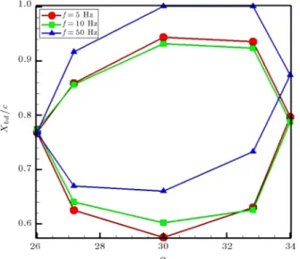
Figures 13 and 14 show the vortex breakdown chordwise location hysteresis loop at M1 = 1:2, =
30, and pitch amplitudes of 4 and 8, respectively,
with dierent frequencies. It is seen that increasing frequency makes the loop slightly narrower, i.e. the amplitude of breakdown location oscillation becomes more limited. Also, it is seen that at amplitude of 4, changing the frequency from 10 Hz to 50 Hz shifts
the breakdown mean location downstream. If the wing were stationary, the quantity Xbd=c would be
maximum at minimum angle of attack and minimum at maximum angle of attack. However, it can be seen in the last three gures that this is not true for the oscillating wing and breakdown location has a large phase dierence with wing motion. A time
Figure 13. Frequency eect on vortex breakdown chordwise location at M1= 1:2, 0= 30, and = 4.
Figure 14. Frequency eect on vortex breakdown chordwise location at M1= 1:2, 0= 30, and = 8.
delay also exists in ow pattern in pitching motion with respect to the stationary ow eld. The authors showed that the time lag associated with ow pattern (vortex formation) was approximately T=8. However, these two events have very dierent time scales. The time lag of ow pattern is very small compared to the large time lag of breakdown location.
3.3. Aerodynamic coecients
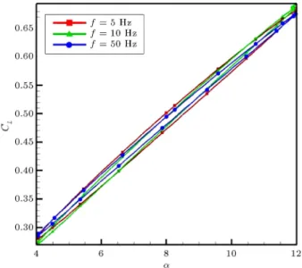
Figures 15 to 23 show the lift or drag coecients versus angle of attack hysteresis loops for dierent ow conditions. Directions of the loops are clockwise. In Figure 15 are compared the hysteresis loops for four dierent Mach numbers when other parameters are xed. Fluctuations seen in the M1 = 0:4 curve are
Figure 15. Frequency eect on lift coecient at M1= 1:2, 0= 8, and = 4.
Figure 16. Mach number eect on lift coecient at 0= 20, = 4, and f = 10 Hz.
Figure 17. Mach number eect on drag coecient at 0= 20, = 4, and f = 10 Hz.
Figure 18. Frequency eect on lift coecient at M1= 1:2, 0= 8, and = 8.
due to inherent ow unsteadiness caused by vortex breakdown. They also exist in M1 = 0:8 curve,
though they are less obvious. Increasing Mach number increases the lift in subsonic cases and decreases it in supersonic cases. This trend is expected, as linear theory predicts it. It makes the loop narrower and decreases the curve slope at supersonic cases. A similar trend is observed for drag coecient in Figure 16, although the hysteresis is small in drag coecient compared to that in the lift coecient.
Comparison of Figures 17 and 18 shows that the hysteresis loop is wider for lower frequencies at 0= 8
and = 4, but it is vice versa at higher pitching
amplitude of = 8. Noticing Figures 19 to 22, we
Figure 19. Frequency eect on lift coecient at M1= 1:2, 0= 20, and = 4.
Figure 20. Frequency eect on lift coecient at M1= 1:2, 0= 20, and = 8.
the lift coecient and widens the loop severely in cases where vortex breakdown exists. Also, it can be seen obviously that increasing oscillation amplitude changes the loop shape, especially at higher instantaneous angles of attack.
Figure 24 shows hysteresis loops associated with pitching moment coecient about the mid-chord (axis of rotation) for four dierent Mach numbers when other parameters are xed. Similar to lift and drag coe-cients, the mean value of pitching moment coecient increases in subsonic region and decreases in supersonic region. The loops have an approximately constant slope for M1 0:8. The amount of hysteresis is
reduced with increasing Mach number, which results in narrower loops and less phase dierence. Eight-shape phenomenon is observed for M1= 0:8.
Figure 21. Frequency eect on lift coecient at M1= 1:2, 0= 30, and = 4.
Figure 22. Frequency eect on lift coecient at M1= 1:2, 0= 30, and = 8.
4. Conclusion
Flow elds over a 60 pitching delta wing with sharp
leading edge, from subsonic to supersonic ow regimes, were computationally simulated using compressible 3D Navier-Stokes equations on an unstructured grid and a k !SST solver. Local Mach number and pressure coecient contours showed that vortex breakdown occurred for large enough angles of attack and the time delay associated with it was shown to be large compared to the ow structure variation time delay. For M1= 0:8, 0= 20, and = 4, onset of primary
vortex breakdown occurred before ow reached the 60% chordwise station. For M1 = 1:2, 0 = 20, and
= 4, the vortex did not break down over the wing
Figure 23. Frequency eect on lift coecient at M1= 2,
0= 30, and = 8.
Figure 24. Mach number eect on pitching moment coecient around mid-chord at 0= 20, = 4, and
f = 10 Hz.
onset of primary vortex breakdown occurred before ow reached the 90% chordwise station, but secondary separation experienced breakdown before primary vor-tex. For M1 = 2, 0 = 40, and = 4, primary
vortex breakdown occurred and its location oscillated around the 60% chordwise station. The eects of ow parameters, namely, Mach number, mean angle of attack, motion amplitude, and frequency, on the hysteresis loops of vortex breakdown location over the wing and aerodynamic coecients were investigated. Increasing free-stream Mach number delayed the vortex breakdown. Increasing frequency made the vortex breakdown location loop slightly narrower, i.e. the amplitude of breakdown location oscillation became more limited. Increasing Mach number made the aerodynamic coecient loops narrower and decreased
the curve slope at supersonic cases. Increasing mean angle of attack increased the lift coecient and widened the loop in cases where vortex breakdown existed. In-creasing oscillation amplitude changed the loop shape, especially at higher instantaneous angles of attack. Nomenclature
c Chord
CL Lift coecient
CD Drag coecient
Cp Pressure coecient
f Frequency
k Reduced frequency M Mach number
t Time
T Period
U Velocity
X Chordwise coordinate from the apex of the wing
Angle of attack
Amplitude
Sweep angle ! = 2f Angular velocity Subscripts
bd Breakdown
N Component normal to the leading edge
0 Mean
1 Free-stream References
1. Gursul, I., Gordnier, R. and Visbal, M. \Unsteady aerodynamics of nonslender delta wings", Progress in Aerospace Sciences, 41(7), pp. 515-557 (2005). 2. Gursul, I. \Recent developments in delta wing
aerody-namics", The Aeronautical Journal, 108, pp. 437-452 (2004).
3. Rockwell, D. \Three-dimensional ow structure on delta wings at high angle-of-attack: experimental concepts issues", 31st Aerospace Science Meeting and Exhibit, Reno, Nevada, USA, January 11-14, paper no. 93-0550 (1993).
4. Visbal, M.R. \Computational and physical aspects of vortex breakdown on delta wings", 33rd Aerospace Science Meeting and Exhibit, Reno, Nevada, USA, January 9-12, paper no. 95-0585 (1993).
5. Atta, R. and Rockwell, D. \Hysteresis of vortex devel-opment and breakdown on an oscillating delta wing", AIAA Journal, 25(11), pp. 1512-1513 (1987).
6. LeMay, S.P., Batill, S.M. and Nelson, R.C. \Vortex dy-namics on a pitching delta wing", Journal of Aircraft, 27(2), pp. 131-138 (1990).
7. Gursul, I. and Yang, H. \On uctuations of vortex breakdown location", Physics of Fluids, 7(1), pp. 229-231 (1995).
8. Gursul, I. and Ho, C.M. \Vortex breakdown over delta wings in unsteady freestream", AIAA Journal, 32(2), pp. 433-436 (1994).
9. Lin, J.C. and Rockwell, D. \Transient structure of vortex breakdown on a delta wing", AIAA Journal, 33(1), pp. 6-12 (1995).
10. Jones, M., Hashimoto, A. and Nakamura, Y. \Criteria for vortex breakdown above high-sweep delta wings", AIAA Journal, 47(10), pp. 2306-2320 (2009).
11. Goruney, T. and Rockwell, D. \Eect of pitch rate on near-surface topology on a delta wing", AIAA Journal, 48(6), pp. 1207-1220 (2010).
12. Jian, L., Haisheng, S., Zhitao, L. and Zhixiang, X. \Numerical investigation of unsteady vortex break-down past 80=65double-delta wing", Chinese
Jour-nal of Aeronautics, 27(3), pp. 521-530 (2014). 13. Stanbrook, A. and Squire, L.C. \Possible types of
ow at swept leading edges", Aeronautical Quarterly, 15(2), pp. 72-78 (1964).
14. Miller, D.S. and Wood, R.M. \Leeside ows over delta wings at supersonic speeds", Journal of Aircraft, 21(9), pp. 680-686 (1984).
15. Szodruch, J.G. and Peake, D.J. \Leeward ow over delta wings at supersonic speeds", Report NASA-TM No. 81187 (1980).
16. Seshadri, S.N. and Narayan, K.Y. \Possible types of ow on lee-surface of delta wings at supersonic speeds", The Aeronautical Journal, 5, pp. 185-199 (1988). 17. Brodetsky, M.D., Krause, E., Nikiforov, S.B., Pavlov,
A.A., Kharitonov, A.M. and Shevchenco, A.M. \Evo-lution of vortex structures on leeward side of a delta wing", Journal of Applied Mechanics and Technical Physics, 42(2), pp. 243-254 (2001).
18. Brodetsky, M.D. and Shevchenco, A.M. \Some fea-tures of a separated ow and supersonic vortex struc-ture at the leeside of a delta wing", Proc. of the IUTAM Symp. on Separated Flows and Jets, Berlin-Heidelberg, Germany, 9-13 July, pp. 341-344 (1990).
19. Imai, G., Fujii, K. and Oyama, A. \Computational analyses of supersonic ows over a delta wing at high
angles of attack", 25th International Congress of the Aeronautical Sciences (ICAS), Hamburg, Germany, 3-8 September (2006).
20. Oyama, A., Ito, M., Imai, G., Tsutsumi, S., Ami-tani, N. and Fujii, K. \Mach number eect on ow eld over a delta wing in supersonic region", 46th AIAA Aerospace Sciences Meeting and Exhibit, Reno, Nevada, USA, 7-10 January, paper no. 354 (2008). 21. Schiavetta, L.A., Boelens, O.J. and Fritz, W. \Analysis
of transonic ow on a slender delta wing using CFD", 24th Applied Aerodynamics Conf., San Francisco, Cal-ifornia, USA, 5-8 June, paper no. 3171 (2006). 22. Schiavetta, L.A., Badcock, K.J. and Cummings, R.M.
\Comparison of DES and URANS for unsteady vor-tical ows over delta wings", 46th AIAA Aerospace Sciences Meeting and Exhibit, Reno, Nevada, USA, 8-11 January, paper no. 1085 (2007).
23. Younis, Y., Bibi, A., Haque. A.U., and Khushnood, S. \Vortical ow topology on windward and leeward side of delta wing at supersonic speed", Journal of Applied Fluid Mechanics, 2(2), pp. 13-21 (2001).
24. Hadidoolabi, M. and Ansarian, H. \Computational investigation of the ow structure over a pitching delta wing at supersonic speeds", Proceedings of the Insti-tution of Mechanical Engineers, Part G: Journal of Aerospace Engineering, 230(7), pp. 1334-1347 (2016). DOI: 10.1177/0954410015608207.
25. Gordnier, R.E. and Visbal, M.R. \High-order simula-tions of low sweep delta wing ows using ILES and hybrid RANS/ILES models", 44th AIAA Aerospace Sciences Meeting and Exhibit, Reno, Nevada, USA, 9-12 January, paper no. 504 (2006).
Biographies
Mostafa Hadidoolabi is an Associate Professor and PhD advisor at Malek Ashtar University of Technology, Iran. His area of research includes CFD, applied aerodynamics, wind tunnel design, etc.
Hossein Ansarian received his BS and MS degrees from Sharif University of Technology in 2007 and 2009, respectively, and his PhD degree from Malek Ashtar University of Technology in 2016. Currently, His main research interest is the application of CFD in simulation of unsteady aerodynamic ows, including delta wing ows.