International Journal of Communication Networks and Information Security (IJCNIS) Vol. 9, No. 2, August 2017
Distributed Fault-Tolerant Algorithm for Wireless
Sensor Network
Chafiq Titouna
1,2, Mourad Gueroui
2, Makhlouf Aliouat
3, Ado Adamou Abba Ari
2,4and Adouane Amine
51
Computer Science Departement, Faculty of Technology, University of M'sila, 28000 M'sila, Algeria
2
LI-PaRAD Laboratory, University Paris Saclay, University of Versailles Saint-Quentin-en-Yvelines, France 3
Computer Science Departement, Faculty of Sciences, University of Setif1, 19000 Setif, Algeria
4
Mathematics and Computer Science Department, Faculty of Sciences, University of Maroua, Cameroon
5
Mathematics and Computer Science Department, Faculty of Sciences, University of Alger 1, 16000 Alger 1, Algeria
Abstract: Wireless Sensor Networks (WSNs) are a set of tiny
autonomous and interconnected devices. These nodes are scattered in a region of interest to collect information about the surrounding environment depending on the intended application. In many applications, the network is deployed in harsh environments such as battlefield where the nodes are susceptible to damage. In addition, nodes may fail due to energy depletion and breakdown in the onboard electronics. The failure of nodes may leave some areas uncovered and degrade the fidelity of the collected data. Therefore, establish a fault-tolerant mechanism is very crucial. Given the resource-constrained setup, this mechanism should impose the least overhead and performance impact. This paper focuses on recovery process after a fault detection phase in WSNs. We present an algorithm to recover faulty node called Distributed Fault-Tolerant Algorithm (DFTA). The performance evaluation is tested through simulation to evaluate some factors such as: Packet delivery ratio, control overhead, memory overhead and fault recovery delay. We compared our results to a referenced algorithm: Fault Detection in Wireless Sensor Networks (FDWSN), and found that our DFTA performance outperforms that of FDWSN.
Keywords: Wireless sensor networks, fault tolerance, connectivity restoration.
I.
Introduction
A wireless sensor network (WSN) consists of a possibly large number of wireless devices able to take environmental measurements. Typical examples include temperature, light, sound, and humidity. These sensed data are transmitted over a wireless channel to a base station (BS) that makes decisions based on these data [1, 2]. WSNs have infiltrated our daily life, such as medical monitoring [3], military surveillance [4, 5], vehicle monitoring [6], home automation monitoring [7], habitat monitoring [8], building structures monitoring, and industrial plant monitoring [9–11].
However, in some applications, nodes are deployed in remote and harsh environments (forest fire, earthquake or chemical spill). In such areas, nodes can be failed due to the energy depletion, hardware failures, communication link errors and even intrusion from attackers. These problems reduce the quality of the gathered data and the entire network. At this stage, it is necessary to set up a mechanism to ensure the quality of the collected data in order to allow taking suitable decision. Therefore, WSN should possess a mechanism of fault tolerance. It can be defined as the ability of a system to deliver a desired level of functionality in the presence of faults [12]. Fault tolerance should be seriously considered in many sensor network applications. Actually, extensive work has been done on fault tolerance and it has been one of the most important topics in WSNs [13, 14, 26].
In this paper, in order to recover the system after fault detection phase, a distributed fault-tolerant algorithm for WSN called DFTA is proposed. To achieve the proposal, an
extension of our previous work [15] is done. This later ensures a detection phase and it can detect faulty nodes. The performance analysis shows that the proposed algorithm outperforms the compared algorithm in terms of packet delivery ratio, fault recovery delay, control and memory overhead. In short, our main tasks can be summarized as follows:
• Elimination of faulty nodes detected in detection phase (described in details in [15]);
• Selection of recovery nodes to replace the faulty nodes;
• Simulation of the DFTA in order to highlight its performance.
The rest of the paper is organized as follows: Section 2 presents some related work. In Section 3, we describe our recovery algorithm and illustrate it through examples. We provide in Section 4 performance results and in Section 5 we conclude the paper.
2. Related work
International Journal of Communication Networks and Information Security (IJCNIS) Vol. 9, No. 2, August 2017
so that nodes can discover each other and recovery can take place. A distributed fault detection algorithm for WSNs named FDWSN has been proposed in [24]. Every node discerns its own status in view of local comparisons of its sensed data with the data of neighboring nodes for q times to detect transient fault. The authors used a redundancy matrix to save all results of comparison. After, the status of the node is declared as good if the sensed data are similar. Finally, each sensor node with a defined status will broadcast its status to its neighbors to facilitate them for determining their own status. This scheme can detect and isolate faulty nodes with high detection accuracy. Transient faults are also tolerated by using time redundancy.
In the present literature, it supposed that WSN is previously requires a mobile nodes which they can move without any constraint. This assumption is not easy to ensure in real environment and in all applications. We noticed also that some nodes with low battery power are incapable to do the recovery process (i.e., which requires node's movement) due to their low battery power and their position in the network. The detection of faulty node in many previous works is based on Hello message mechanism. This technique is not efficient to identify all faulty nodes (i.e., malicious node). Therefore, a novel algorithm is needed to detect and recover faulty nodes without hard assumptions. Our proposed algorithm uses our scheme (described in [15]) to detect faulty nodes and assumes an efficient recovery process.
3. Distributed Fault-Tolerant Algorithm
In this section, we present our proposed algorithm, named Distributed Fault-Tolerant Algorithm (DFTA). We begin first by defining some assumptions. We then provide details of the mechanism used for recovering faulty nodes. DFTA operates in two phases: (a) First, elimination of faulty nodes from the network. (b) Second, selection of recovery nodes.
3.1 System Assumptions
A WSN is typically consisting of a large number of nodes scattered over a region of interest to monitor a particular physical phenomenon. Some assumptions, complying with practical aspect, have to be considered in our algorithm. The first assumption is that all sensed data are forwarded from sources to a central node called Base Station (BS) via Cluster-Heads (CH). The second is that, all nodes are stationary and its batteries cannot be recharged. We recognize that local processing may occur to reduce overall communication costs. The next assumption we make is that all nodes are homogeneous in terms of energy, communication and processing capabilities. They are assigned a unique identifier (ID). Finally, we also assume that we do not have malicious attacks on the network.
3.2 Algorithm Design
If a node is diagnosis as a faulty one, then it should be eliminated from the network and replaced by a sleeping node to ensure its functions (such as sensing and routing packets). One of the sleeping nodes belongs to the same cluster, will take the place of a faulty node. The same process of replacement will continue until arriving:
• at the black list will be empty (i.e., if a faulty node is recovered by a sleeping one, then it will removed from the black list. This list contains all faulty nodes detected
in detection phase); or
• at a faulty node does not have any neighbor in sleeping state (i.e., all sleeping nodes, belong to that faulty node, and are already activated).
The idea is to substitute the faulty node by a sleeping one with a connectivity degree higher and belongs to the same cluster. Using this technique prolong the global network lifetime by using a sleeping nodes and avoid partition of the network by replacement of the faulty nodes. For that, our algorithm consists of two phases: an elimination phase and a recovery phase. We describe them in the following subsections.
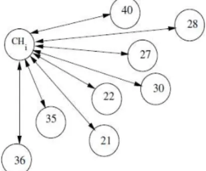
Figure 1. Example of cluster (CHi).
3.2.1 Elimination phase
This phase is divided into three steps: creation of healthy node’s vector step, selection of sleeping node step and elimination of faulty node step. The following subsections describe each step.
(a) Creation of Healthy Node’s Vector Step
Each CH creates a vector of healthy node (VHN) which will contain all nodes belong to this cluster. This step is launched just after deployment of the network. We consider a cluster
CHi represented in Figure 1. So, the CHi will create a vector
of node VHNi (see Figure 2) and insert all IDs of nodes
belong to this cluster.
Figure 2. VHNi (case CHi).
(b) Selection of Sleeping Nodes Step
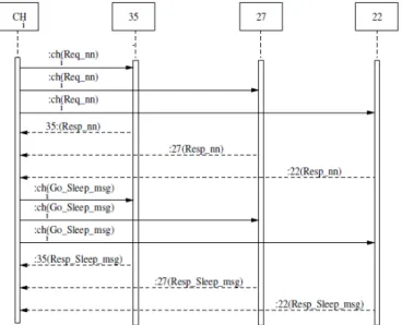
In this step, the CH chooses which nodes should be in sleep mode. The CH can take into account the energy remaining of a node, the geographic position of a node, or the degree of connectivity of a node. In this paper, we based on the degree of connectivity of nodes, i.e., the CH selects the node that has fewer neighbors. To start the selection of sleeping node, the CH broadcasts a Req_nn message to know the number of neighbors of each node. When a node receives a Req_nn message, it will respond with Resp_nn message to inform the
CH about the number of neighbors in its transmission range.
When the CH receives all Resp_nn messages, the selection of sleeping nodes is launched by selecting only nodes with number of neighbors is less than α threshold (α can be equal
to the average number of node belongs to the same cluster). The CH sends a Go_Sleep_msg message to all selected nodes. A response like Resp_Sleep_msg message, it will be sent by the selected nodes to indicate to CH that they will
International Journal of Communication Networks and Information Security (IJCNIS) Vol. 9, No. 2, August 2017
Figure 3. Example of message exchanging between CHi and
selected sleeping nodes (35, 27 and 22).
switch to sleep mode. E.g., consider Figure 1. The CHi selects for example nodes with IDs: 35, 27 and 22. The IDs of selected nodes is encircled (see Figure 2). Figure 3 represents message exchanging required to select sleeping nodes (the figure shows only message exchanging between
CHi and three nodes 35, 27 and 22).
(c) VHN’s Update Step
After the phase of detection of faulty nodes (see more details in [13]) the CH holds a black list (BL) which contains all the faulty nodes detected. They should be eliminated and removed from VHN. So, to do that, every CH updates its own
VHN by proceeding to an elimination of all faulty nodes’ID
from the vector. E.g., consider the example in Figure 1. We suppose that node 30 in BL. So this node should be removed from the vector (we just underlined its ID in Figure 2). The next subsections describe the steps required for the recovery phase.
3.2.2 Recovery phase
This phase describes the recovery process launched by CH. It is performed in two steps: selection of recovery node and updating of VHN.
(a) Principe
DFTA recognizes two transition states for nodes as shown in
Figure 4, active and sleeping. Initially all nodes in the network are in active state. This means that all nodes will turn their radio on until receiving a message (Go_Sleep_msg) from the CH (see previous subsection) to switch their radio off and move to sleep mode. Returns back to the active state happens when the CH selects node (it is in sleeping state) to recover one or more faulty nodes (more details in next subsection).
Figure 4.The DFTA node state transitions.
Figure 6. Message exchanging required for selecting RN
(level 2).
To do that, CH will send a Wakeup_msg message to these nodes (sleeping nodes selected). So, the transition between the two states, active and sleeping, is ordered by the CH and it is performed based on messages exchanging (see Figure 4). We implement this technique in CH, to minimize the number of active nodes. Such technique permits a maximization of the lifetime of the entire network.
(b) Selection of Recovery Nodes Step
The process of selection of recovery nodes implies an activation of some sleeping nodes. The CH sends a
Wakeup_msg message to all sleeping nodes belong to the
same cluster of the faulty nodes. However, the sleeping node belonging to other clusters, that do not contain any faulty nodes, its corresponding CHs do not send any messages. E.g., consider the previous example in Figure 1, the sleeping nodes which receive the Wakeup_msg are: The nodes 22, 27 and 35.
At receiving the Wakeup_msg message, the sleeping nodes turn their radio on and send back a wakeup acknowledgement message (Wakeup_ack) to the CH to indicate its new state (active state). The CH sends now a request (Req_hop_reqr) to know the number of hops required to reach the faulty nodes from these sleeping ones. The sleeping nodes update their routing table and respond to the CH using a simple packet (Resp_hop_reqr). The structure of this packet is described in Figure 5.
Figure 5.Packet format.
When all Resp_hop_reqr received, the CH creates a Hop Required Table (HRT). This table is used to choose the appropriate recovey node (RN). E.g., the Table 1 summarizes
srcid desid Fn(1)_id hops_nd Fn(2)_id hops_nd
….. …... …. …… fn(n)_id hops_nd
recieve ‘Wakeup_msg ‘
sleeping active
International Journal of Communication Networks and Information Security (IJCNIS) Vol. 9, No. 2, August 2017
the number of hops required for the nodes 22, 27 and 35 to reach the faulty nodes 30.
The CH chooses nodes which require fewer hops to reach faulty nodes. E.g., consider the Table 1, the node with ID 22 needs 1 hop to reach node 30. So, the CH selects it as RN. A
Go_Sleep_msg message is sent to the not selected nodes
(e.g., 27 and 35) to go back to sleep mode. A response
Resp_Sleep_msg message, it will be sent by the selected
nodes to the CH. Figure 6 shows the previous exchange messages.
Table 1. HRT of cluster i (FN=30, Sleeping nodes=22, 27, 35)
(c) VHN’s Update Step
The CH should update the vector of healthy node after a recovery process. All sleeping nodes that are selected for recovering faulty nodes should be mentioned in VHN. E.g., consider the example in previous section, the node with ID 22 will be considered as an active node.
Table 2. Simulation parameters.
Parameter Value
Area size 1000 × 1000
Number of nodes 20, 40, 60, 80, 100, 200
Transmission power 2mW, 4mW
Transmission channel Wireless channel
Propagation model log Normal path loss model
Data packet size 32 bytes
Bandwidth 200 Kilobytes/second
Radio layer CC2420 radio layer
Queue size 50 packets
4. Evaluation
We have conducted several series of simulations using the
TOSSIM simulator [25] in order to evaluate the performance
of our proposed algorithm. For comparison purposes, we take as metric the packet delivery ratio (PDR), the control overhead (CO), the memory overhead (MO) and the fault recovery delay (FRD). The key simulation parameters are summarized in Table 2.
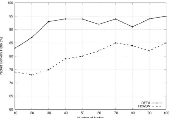
4.1 Analysis of Packet Delivery Ratio (PDR)
Packet delivery ratio is calculated as the number of packets received by a receiver divided by the number of packets sent by a sender. This metric characterizes the percentage of successful source data packet delivery; ideally, this should be 100%. Figure 7 shows the total number of data packets received by the CH over the number of nodes (with node transmission power (TP) set to 2 mW). We remark that the amount of data collected by the BS from every sensor node is much more important with our DFTA algorithm then the
FDWSN protocol. We can say that FDWSN generates more
trafic which causes a set of collision in wireless channel. The retransmission will become more frequent and the PDA will decrease. To test our algorithm’s performance, we made TP = 4mW. The Figure 8 shows a good result, which confirms the accuracy of our solution. When we increase the transmission power, the number of neighbors of recovery sensor node increases. However, for FDWSN, we noticed that there is a less in packet delivery ratio because FDWSN
requires a set of iterations that consumes battery power which increases faulty sensor nodes.
Figure 7. PDR vs. number of nodes, TP = 2mW.
Figure 8. PDR vs. number of nodes, TP = 4mW.
Figure 9. CO vs. number of nodes, TP = 2mW.
4.2 Analysis of control overhead (CO)
The detection and recovery of faulty node is an additional task in WSN. It requires extra control packets. This metric computes the additional control packets needed to perform the recovery process. In Figure 9, we noticed that for both
DFTA and FDWSN increase with the increase of the number
of nodes. More nodes require more control packets to achieve the recovery process. However, the FDWSN protocol uses more control packet comparing with our DFTA since the later does not need any iteration in detection process. The
FDWSN’s detection of faulty nodes process is very
Sleeping node ID Hop required
22 1
27 1
International Journal of Communication Networks and Information Security (IJCNIS) Vol. 9, No. 2, August 2017
complicated and it based on collecting neighbors’ information to detect the faulty nodes. When we increased the node transmission power to 4 mW (see Figure 10),
FDWSN needs more packet of control. However, our
algorithm performs better because the recovery node can reach more nodes in the same cluster.
Figure 10. CO vs. number of nodes, TP = 4mW.
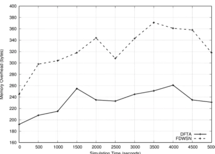
Figure 11. MO vs. simulation time (TP = 2mW, number of node = 100).
Figure 12. MO vs. simulation time (TP = 4mW, number of node = 100).
Figure 13. FRD vs. number of faulty node (number of node = 100).
Figure 14. FRD vs. number of faulty node (number of node = 200).
4.3 Analysis of memory overhead (MO)
The memory overhead metric represents the average number of bytes needed to be stored in the memory of all nodes that are implied in recovery process. We computed for DFTA and
FDWSN the additional memory space needed to insure the
all process. We plotted the result in Figure 11. During the simulation, we noticed a change in the quantity of bytes required for both algorithms. This instability in memory overhead is due to the mechanism deployed on nodes. We observed that the memory overhead in DFTA is less than in
FDWSN because the later requires more memory to store
transient fault matrix and other parameters. In Figure 12 (node transmission power = 4 mW), we observed better results comparing with previous curves (transmission power = 2 mW) of two algorithms with DFTA less memory overhead.
4.4 Analysis of fault recovery delay (FRD)
The last performance metric is fault recovery delay. FRD for
DFTA and FDWSN are shown in Figure 13 and 14 for 100
International Journal of Communication Networks and Information Security (IJCNIS) Vol. 9, No. 2, August 2017
the fact that FDWSN requires more time to create and compare transient fault matrices for each faulty node. However, the DFTA can recover a multiple faulty nodes if the position of recovery node selected is close of faulty nodes (i.e., one sleeping node can recover multiple faulty nodes). When we increased the number of node in network to 200, we observed a small increase for DFTA compared with FDWSN. The later requires more time to recover from faulty nodes because it needs to compare transient fault matrices.
5. Conclusion
In this paper, we introduced an extension of our previous work. We presented a recovery algorithm to ensure a tolerate process after a faulty node detection. Our algorithm is based on using sleeping node as a recovering node to maximize the lifetime of the entire network. It is divided into two phases, an elimination phase and a recovery phase. These phases are ordered by CHs in distributed manner and they are launched just after the detection's process of faulty nodes (described in the previous work). The main idea is to eliminate and replace faulty nodes using selected sleeping nodes. This technique restores the network connectivity and prolongs the lifetime of the network. We have evaluated our DFTA algorithm with
FDWSN protocol under various metrics. The simulation
results show well that our algorithm outperforms compared to the results of FDWSN.
References
[1] B.O. Yenké, D.W. Sambo, A.A.A. Ari and A. Gueroui, “ MMEDD: Multithreading Model for an Efficient Data Delivery in wireless sensor networks,” International Journal of Communication Networks and Information Security, Vol. 8, No.3, pp. 179-186, 2016.
[2] J. Shobana and B. Paramasivan, “GCCP - NS: Grid based Congestion Control protocol with N-Sinks in a Wireless Sensor Network,” International Journal of Communication Networks and Information Security, Vol. 7, No. 2, pp. 99-105, 2015.
[3] S. Nourizadeh, C. Deroussent, Y.Q. Song and J.P. Thomesse, “Medical and home automation sensor networks for senior citizens telehomecare,” IEEE International Conference on Communications Workshops, Dresden, Germany, pp. 1-5, 2009.
[4] T. He, S. Krishnamurthy, L. Luo, T. Yan, L. Gu, R. Stoleru, G. Zhou, Q. Cao, P. Vicaire, J. A. Stankovic, T. F. Abdelzaher, J. Hui, B. Krogh, “ Vigilnet : An integrated sensor network system for energy efficient surveillance” Journal ACM Transactions on Sensor Networks, Vol. 2, No. 1, pp. 1-38, 2006.
[5] P. Vicaire, T. He, Q. Cao, T. Yan, G. Zhou, L. Gu, L. Luo, R. Stoleru, J. A. Stankovic and T. Abdelzaher, “ Achieving long term surveillance in vigilnet” Journal ACM Transactions on Sensor Networks, Vol. 5, No. 1, pp. 1-39, 2009.
[6] H. Song, S.C. Zhu, G.H. Cao, “SVATS: A sensor-network-based vehicle anti-theft system,” The 27th Conference on Computer Communications, Phoenix, AZ, USA, pp. 2128-2136, 2008.
[7] L. Yang, M. Ji, Z. Gao, W. Zhang and T. Guo, “Design of home automation system based on ZigBee wireless sensor network,” International Conference on Information Science and Engineering, Nanjing, China, pp. 2610-2613, 2009. [8] R. Szewczyk, A. Mainwaring, J. Polastre, J. Anderson and D.
Culler, “An analysis of a large scale habitat monitoring application,” The 2nd international conference on Embedded
networked sensor systems, Baltimore, Maryland, USA, pp. 214–226, 2004.
[9] G. Toll, J. Polastre, R. Szewczyk, D. Culler, N. Turner, K. Tu, S. Burgess, T. Dawson, P. Buonadonna, D. G ay and W. Hong “A macroscope in the redwoods,” The 3rd international conference on Embedded networked sensor systems 5, San Diego, California, USA, pp. 51–63, 2005.
[10]P. Sikka, P. Corke, P. Valencia, C. Crossman, D. Swain and G. B. Hurley, “Wireless adhoc sensor and actuator networks on the farm” The 5th international conference on Information processing in sensor networks, Nashville, Tennessee, USA, pp. 492–499, 2006.
[11]G. Werner, P. Swieskowski and M. Welsh, “Demonstration: real-time volcanic earthquake localization,” The 4th international conference on Embedded networked sensor systems, Boulder, Colorado, USA, pp. 357–358, 2006
[12]M. Demirbas, “ Scalable design of fault-tolerance for wireless sensor networks”, Ph.D. thesis, The Ohio State University, Columbus, OH, 2004.
[13]S. Chouikhi, I. Elkorbi, Y. Ghamri-Doudane and L. A. Saidane, “A survey on fault tolerance in small and large scale wireless sensor networks,” Elsevier Computer Communications, Vol. 69, pp. 22-37, 2015.
[14]L. Paradis and Q. Han, “A Survey of Fault Management in Wireless Sensor Networks,” Journal of Network and Systems Management, Vol. 15, No. 2, pp. 171-190, 2007.
[15]C. Titouna, M. Aliouat and M. Gueroui, “ FDS: Fault Detection Scheme for Wireless Sensor Networks,” Wireless Personal Communication, Vol. 86, No. 2, pp. 549-562, 2016. [16]C. Titouna, M. Aliouat and M. Gueroui, “Outlier detection
approach using bayes classifiers in wireless sensor networks,” Wireless Personal Communication, Vol. 85, No. 3, pp. 1009-1023, 2015.
[17]W. Wang, V. Srinivasan and K.C. Chua, “Using mobile relays to prolong the lifetime of wireless sensor networks,” The 11th international conference on mobile computing and networking, Cologne, Germany, pp. 270-283, 2005.
[18]P. Basu and J. Redi, “Movement control algorithms for realization of fault-tolerantad-hoc robot networks,” IEEE Network, Vol. 18, No. 4, pp. 36-44,
[19]A. A. Abbasi, K. Akkaya and M. Younis, “A Distributed Connectivity Restoration Algorithm in Wireless Sensor and Actor Networks,” The 32nd IEEE Conference on Local Computer Networks IEEE Computer Society, pp. 496-503, 2007.
[20]K. Akkaya, A. Thimmapuram, F. Senel and S. Uludag, “Distributed recovery of actor failures in wireless sensor and actor networks,” IEEE Wireless Communications and Networking Conference, pp. 2480-2485, 2008.
[21]N. Tamboli, and M. Younis, “ Coverage-aware connectivity restoration in mobile sensor networks,” Journal of Network and Computer Applications, Vol. 33, No. 4, pp. 363-374, 2010. [22]K. Akkaya, F. Senel, A. Thimmapuram and S. Uludag, “Distributed recovery from network partitioning in movable sensor/actor networks via controlled mobility,” IEEE Transactions on Computers, Vol. 59, No. 2, pp. 258-271, 2010. [23]M. Younis, S. Lee, S. Gupta and K. Fisher, “A localized
self-healing algorithm for networks of moveable sensor nodes,” IEEE international conference on global communications (Globecom’08), New Orleans, LA, USA, pp. 1–5, 2008. [24]M. H. Lee and Y. H. Choi, “ Fault detection of wireless sensor
networks,” Computer Communications, Vol. 31, No. 14, pp. 3469-3475, 2008.
[25]P. Levis, N. Lee, M. Welsh and D. Culler, “ TOSSIM: accurate and scalable simulation of entire TinyOS applications”. The 1st international conference on Embedded networked sensor systems (SenSys), Los Angeles, California, USA, pp. 126-137, 2003.