Electronic-Key-System
Manual
Electronic-Key Adapter EKS and EKS
FSA
with PROFINET Interface
Order no. 109 283
Table of contents
1 General notes ... 4
1.1 Use of the manual ... 4
1.1.1 Explanation of symbols ... 4
1.1.2 Abbreviations ... 5
1.2 CE conformity... 5
1.3 Approvals ... 5
1.4 Correct use... 6
1.5 Obligations on the operating organization ... 7
2 Safety precautions... 8
3 Function ... 9
3.1 Functional description ... 9
3.1.1 Common functions of EKS Standard and version EKS FSA ... 9
3.1.2 Additional functions of the version EKS FSA ...10
4 Technical data ...11
4.1 Dimension drawing of Electronic-Key adapter ...11
4.1.1 Version EKS-A-IIX-G01-ST02/03 with PROFINET interface ...11
4.1.2 Version EKS-A-IIXA-G01-ST02/03/04 (EKS FSA) with PROFINET interface ...11
4.2 Technical data, Electronic-Key adapter ...12
4.3 Connector assignment ...13
4.3.1 Connection socket for PROFINET interface ...13
4.3.2 Plug-in screw terminals for power supply ...13
4.3.3 Plug-in screw terminals for outputs LA1/LA2 and LB1/LB2 (EKS FSA only) ...13
4.4 DIP switch settings ...14
4.4.1 DIP switch S1 ...14
4.4.2 DIP switch S2 ...15
4.4.3 DIP switch S3 ...15
4.5 LED indicator...16
5 Mounting ...17
7 Setup ... 27
7.1 Requirements ... 27
7.2 Configuration settings ... 28
7.2.1 Modules available in the GSD file for reading data ... 28
7.2.2 Properties for the modules for reading data ... 28
7.2.3 Modules available in the GSD file for writing data ... 29
7.2.4 Properties for the modules for writing data ... 29
7.3 Connecting the EKS to a PROFINET CPU... 30
8 Operation in the PROFINET ... 35
8.1 Communication ... 35
8.2 EKS alarms ... 35
8.3 Read/write operation ... 36
8.3.1 Input area (read process) ... 36
8.3.2 Output area (write process) ... 37
9 Analysis and assignment of DCP name via web interface ... 38
9.1 Network settings for a configuration PC with Windows® XP ... 38
9.2 Configuring the Electronic-Key adapter via the web interface ... 41
9.3 Reading Electronic-Key data using the web interface ... 43
10Exclusion of liability ... 44
11Service and repair ... 44
1 General notes
1.1 Use of the manual
This manual describes the technical features and the function of the EKS Electronic-Key adapter EKS-A-IIX-G01-ST02/03 with PROFINET interface (order no. 106 305) as well as the version
EKS-A-IIXA-G01-ST02/03/04, EKS For Safety Applications (EKS FSA, order no. 106 306). The complete evaluation and interface electronics for data transmission are integrated into these units.
1.1.1 Explanation of symbols
The following symbols are used in this manual to identify important instructions and useful information:
Danger!
Identifies an immediate hazard. If not avoided, the consequence will be fatality or very serious injuries.
Warning!
Identifies a possible hazard. If not avoided, the consequence may be fatality or very serious injuries.
Caution!
Identifies a possible hazard. If not avoided, minor injuries or damage may result.
Attention!
Risk of damage to material or machine or degradation of function.
Information!
1.1.2 Abbreviations
The following abbreviations are used in this manual:
DCP Discovery and Configuration Protocol
DIP Dual Inline Package
E²PROM Electrically Erasable Programmable Read-Only Memory
EKS Electronic-Key-System
EKS FSA Electronic-Key-System For Safety Applications
GSD Geräte Stammdaten (device data)
GSDML Generic Station Description Markup Language (special XML file with device parameters for the configuration of the control system)
IP Internet Protocol
LED Light Emitting Diode
LSB Least Significant Bit
MSB Most Significant Bit
PA PolyAmide
RD Receive Data
ROM Read-Only Memory
TCP/IP Transmission Control Protocol / Internet Protocol
TD Transmit Data
1.2 CE conformity
The EKS Electronic-Key adapters with PROFINET interface conform to the EMC directive 2004/108/EC (2004/108/EC, 2004/108/CE).
The Electronic-Key adapters comply with the following European/international standards:
EN 55011 Industrial, scientific and medical equipment - Radio-frequency disturbance characteristics - Limits and methods of measurement
EN 61000-6-2 Electromagnetic compatibility (EMC) - Part 6-2: Generic standards - Immunity for industrial environments
1.3 Approvals
The EKS Electronic-Key adapters with PROFINET interface are certified in accordance with (UL file number E240367).
For use and operation as per the requirements, a power supply with the feature for use in class 2 circuits must be used.
1.4 Correct use
As part of a higher-level overall system, the EKS Electronic-Key adapter is used for access control and monitoring on control systems or parts of control systems for machine installations. EKS can be used, for example, as part of an overall system for checking access rights for operating mode selection. However, it is not permitted to directly derive the operating mode from the access rights on the Electronic-Key. If the selection of the operating mode is relevant for safety, this must not be performed by means of the EKS; instead an
additional device must be used to select the operating mode. This is possible using a pushbutton or selector switch, for example.
The version EKS FSA has outputs that can be utilized to form a safe shutdown signal (for block diagram see section 3.1.2). For this purpose a safe evaluation must be included downstream. The EKS FSA can then be used for safety-relevant tasks. The machine must be reset to a safe operating mode by removing the Electronic-Key. A hazard analysis on this aspect must be prepared as per the requirements in the machinery directive. The risk and the necessary risk minimization by technical means must be determined using a suitable standard. The following requirements must be met for usage:
The data signal (channel LB) and the switched output LA1/LA2 (channel LA) must be polled by a safe downstream evaluation to suit the risk determined. The data line (channel LB) is used to supply the information as to whether or not an Electronic-Key is inserted and which access rights are assigned to the Electronic-Key. The output LA1/LA2 (channel LA) is used for the redundant supply of the information as to whether or not an Electronic-Key is inserted (independent of the access rights). The data line or,
alternatively, the switched output LB1/LB2 can be used as channel LB. The output LB1/LB2 is used to supply (like LA1/LA2) only the information as to whether or not an Electronic-Key is inserted (independent of the access rights). The usage of the output LB1/LB2 is optional.
The control system must check whether the Electronic-Key inserted is authorized to select the operating mode and whether the access rights on the Electronic-Key permit operation in the operating mode currently selected.
The user must select the related operating mode using the control system or another suitable circuit.
The manufacturer of the system must check which safety level is reached with the overall system and whether the overall system provides adequate safety against hazards in the intended application.
Information!
The machinery directive 2006/42/EC provides information on selection of the operating mode. It is imperative that this information be followed.
When designing machines and using the Electronic-Key adapter, the national and international regulations and standards specific to the application must be observed, e.g.:
EN 60204, Safety of machinery - Electrical equipment of machines
EN 12100-1, Safety of machinery - Basic concepts, general principles for design - part 1: basic terminology, methodology
EN 62061, Safety of machinery – Functional safety of safety-related electrical, electronic and programmable electronic control systems
EN ISO 13849-1, Safety of machinery. Safety related parts of control systems - part 1: General principles for design
The Electronic-Key adapter must only be employed and used in accordance with
this manual and
other documentation referred to in this manual.
The EKS Electronic-Key adapter is not a safety component in the sense of the machinery directive.
Without additional precautions the EKS Electronic-Key adapter must not be used to provide a safety function, particularly if failure or malfunction of the unit could endanger the safety or health of people in the operating area of a machine.
1.5 Obligations on the operating organization
The manufacturer and the organization operating the higher-level overall system, e.g. a machine installation, are responsible for the observance of national and international safety and accident prevention regulations
2 Safety precautions
Warning!
The EKS Electronic-Key adapter is not a safety component in the sense of the machinery directive. Without additional precautions the EKS Electronic-Key adapter must not be used to provide a safety function, particularly if failure or malfunction of the unit could endanger the safety or health of persons in the operating area of a machine. On this topic pay particular attention to the sections Correct use (see section 1.4) and Electrical connection (see section 6).
Warning!
Mounting and electrical connection are only allowed to be performed by authorized personnel who are familiar with the applicable regulations on accident prevention and have read and understood this manual.
Furthermore, installation and electrical connection of the version EKS FSA must be performed only by personnel familiar with handling safety components.
Caution!
Modifications to the electronics of the Electronic-Key adapter and any other changes, especially mechanical modifications and reworking, are not permissible and will result in the loss of the warranty.
3 Function
3.1 Functional description
3.1.1 Common functions of EKS Standard and version EKS
FSA
The EKS is used for access control and monitoring on control systems or parts of control systems for machine installations.
Instead of passwords, coded Electronic-Keys are assigned. In this way unauthorized access to control and visualization systems is prevented to the greatest possible extent.
The EKS uses a non-contact, inductive read/write identification system. It comprises:
Electronic-Key
Electronic-Key adapter
The user is responsible for organizing the programming of the application, integration in an overall system and the assignment and use of the freely programmable memory in the Electronic-Key.
Information!
For easier organization and management of your Electronic-Keys and the data they contain, EUCHNER also offers the Electronic-Key Manager (EKM) software. To enter data in the EKM software, an
Electronic-Key adapter with serial interface or USB interface must be in operation on the PC. The Electronic-Key adapter is a read/write system with integrated evaluation unit and interface.
Due to the non-contact transfer of data, from the access side the Electronic-Key adapter has the high degree of protection IP 67, i.e. it is suitable for industrial use. The Electronic-Key adapter can be installed in accordance with DIN 43700 in any control panel with a standard cut-out of 33 mm x 68 mm. The Electronic-Key adapter is fastened by means of screw clamp elements from the rear side of the panel in order to exclude unauthorized tampering from the operator side.
The system is connected via the integrated PROFINET interface that is designed as an RJ45 socket. For the PROFINET connection a separate switch may be required. The device does not have an integrated switch. Setup and system integration can be realized straightforwardly and quickly on the Electronic-Key adapter with PROFINET interface.
The current state of the Electronic-Key adapter is displayed using a 3-color LED.
The Electronic-Keys are tag shaped. The complete transponder with memory chip and antenna is integrated into the Electronic-Key. The transponder does not have a battery.
For operation, the Electronic-Key is inserted in the Electronic-Key adapter and is held in place by a spring clip. The power supply for the transponder and the data are transferred contactlessly between the Electronic-Key adapter and Electronic-Key.
Figure 1: Cut-away illustration of Electronic-Key adapter
The data carrier in the Electronic-Key is equipped with a combined memory:
116 bytes E2PROM (programmable) plus 8 bytes ROM (serial number)
On read/write Electronic-Keys with 116 bytes, the memory is organized in 4-byte blocks. This means a multiple of 4-byte sized blocks must always be written.
3.1.2 Additional functions of the version EKS
FSA
The version EKS FSA has two additional semiconductor relay outputs (LA1/LA2 and optionally LB1/LB2) that are switched off as long as there is no Electronic-Key in the Electronic-Key adapter or if it is not possible to read the Electronic-Key.
The semiconductor relay outputs are electrically isolated from the device electronics and from each other. Either AC or DC can be switched.
Each of the outputs is operated with diversity by a dedicated processor that switches off the outputs on removal of the Electronic-Key (see Figure Block diagram EKS FSA).
4 Technical data
4.1 Dimension drawing of Electronic-Key adapter
For installation in a control panel you must provide a cut-out 33 mm x 68 mm according to DIN 43700.
4.1.1 Version EKS-A-IIX-G01-ST02/03 with PROFINET interface
4.2 Technical data, Electronic-Key adapter
Attention!
All the electrical connections must either be isolated from the mains supply by a safety transformer according IEC 61558-2-6 with limited output voltage in the event of a fault, or by other equivalent isolation measures.
General parameters Value Unit
min. typ. max. Housing Plastic (PA 6 GF30 gray)
Degree of protection acc. to EN 60529 IP 67 in mounted condition
Ambient temperature at UB = 24 V DC 0 + 55 °C Mounting cut-out acc. to DIN 43700 33 x 68 mm Connection for power supply Plug-in screw terminal, 3-pole,
Conductor cross-section 0.14 … 1.5 mm², tightening torque 0.22 Nm
Operating voltage UB
(regulated, residual ripple < 5 %) 20 24 28 DC V Current consumption 150 mA
Interface, data transfer
Interface to the control system Industrial Ethernet (IEEE 802.3) Transfer protocol PROFINET
Data transfer rate (full duplex) 10/100 MBit/s Data connection 1 x RJ45 socket
Data line 2 x 2 twisted-pair copper cables, screened; min. category 5
Cable length 100 m LED indicator green: "Ready" (in operation)
yellow: "Electronic-Key active" * red: "Fault"
FSA (For Safety Applications) version - parameters for floating semiconductor switching contacts LA and LB
Power supply U for load (LA, LB) 24 30 V Switching current (with overload protection) 1 10 50 mA Output voltage UA (LA, LB) in switched state U x 0.9 U V
Resistance in switched state 35 Ohm Capacitive load 1 µF Utilization category according to AC-12
EN IEC 60947-5-2 AC-15 DC-12 DC-13
50 mA / 24 V
Difference time between outputs** (LB first) 200 ms Connection screw terminals, 2 x 2-pole 0.14 1.5 mm²
Reliability values according to EN ISO 13849-1 (only FSA version)
Category (with connected safe evaluation) 3 MTTFd Evaluation of data channel and one
switching contact LA 416
years Evaluation of data channel and both
switching contacts LA and LB 803
years
DC 92 %
* The LED illuminates yellow if there is a functional Electronic-Key in the Electronic-Key adapter.
** If access on the Ethernet interface takes place during insertion or removal of the Electronic-Key, the difference time can be more than 200ms.
4.3 Connector assignment
4.3.1 Connection socket for PROFINET interface
The connection on the Electronic-Key adapter is realized as an RJ45 (8P8C) socket corresponding to ISO IEC 61754-24.
Pin Function
1 Transmit Data + (TD+) 2 Transmit Data - (TD-) 3 Receive Data + (RD+) 6 Receive Data - (RD-)
4.3.2 Plug-in screw terminals for power supply
Information!
The coded plug for connection of the power supply is included with the Electronic-Key adapter.
1 2 3
Coded plug, 3-pole with screw terminals Cond. cross-section 0.14 ... 1.5 mm²
Tightening torque 0.22 Nm
Pin Designation Function
1 UB Power supply DC + 24 V 2 0V Power supply DC 0 V
3 Function earth Electrically connected to the housing
4.3.3 Plug-in screw terminals for outputs LA1/LA2 and LB1/LB2 (EKS
FSA
only)
Information!
The coded plug for connection of the outputs is included with the Electronic-Key adapter.
Coded plug, 2 x 2-pole with screw terminals Cond. cross-section 0.14 … 1.5 mm²
Tightening torque 0.22 Nm
Channel Pin Function
LA
1
Normally open contact channel LA
2 LB
1
Normally open contact channel LB
4.4 DIP switch settings
The device has three DIP switches (S1, S2, S3).
DIP switch Function
S1 (4-fold)
S1.1 … S1.4; write and read settings S2
(8-fold)
S2.1 … S2.8; setting for a fixed DCP name (dependent on the setting of S3) S3
(4-fold)
S3.1 … S3.4; settings for network connection and service
Information!
The settings are only applied when the power supply is switched on.
4.4.1 DIP switch S1
DIP
switch Function Factory setting
S1.1 ON = write protection for Electronic-Key read/write OFF S1.2 No function OFF S1.3 No function OFF S1.4 No function OFF
Information!
It is imperative that all switches without a function (S1.2, S1.3 and S1.4) are set to OFF! In this way problems with any functions added in the future will be avoided.
4.4.2 DIP switch S2
Information!
To be able to define the DCP name using DIP switch S2, all of DIP switch S3 must first be set to OFF. The usage of the switches to assign the DCP name and the IP address is described in the following in section 6.1.1.
DCP name LSB
S2.1 S2.2 S2.3 S2.4 S2.5 S2.6 S2.7
MSB S2.8
Apply from configuration
software*
OFF OFF OFF OFF OFF OFF OFF OFF EKS-PN-1 ON OFF OFF OFF OFF OFF OFF OFF EKS-PN-2 OFF ON OFF OFF OFF OFF OFF OFF EKS-PN-3 ON ON OFF OFF OFF OFF OFF OFF … … … … EKS-PN-254 OFF ON ON ON ON ON ON ON EKS-PN-255 ON ON ON ON ON ON ON ON
*)
The name that was last set in the configuration software is used (factory setting: all in OFF position)
Information!
If a DCP name is set on DIP switch S2, a name set previously will be overwritten.
4.4.3 DIP switch S3
Using DIP switch S3 you define the way the device is to receive its DCP name.
Function S3.1 S3.2 S3.3 S3.4
Assign DCP name via configuration software or set via DIP switch S2. OFF OFF OFF OFF Set DCP name via the web interface. ON OFF OFF OFF Set default IP address ON OFF ON ON Internal function, leave switch OFF OFF
(Factory setting: all in OFF position)
= any switch position
Information!
The usage of the switches to assign the DCP name and the IP address is described in the following in section 6.1.1.
The IP address is always set automatically via the configuration software and assigned via the DCP CPU.
To prevent unauthorized changes to the network, it is sensible to deactivate the web interface after use. For this purpose switch S3.1 is set to OFF.
4.5 LED indicator
The Electronic-Key adapter operating states are indicated using a 3-color LED on the front. The illumination of the LED in any color indicates the presence of the operating voltage.
Color Operating status Description
Red
Electronic-Key adapter powering up
or fault
After the application of the power supply, the LED is constantly illuminated red during power up. The completion of the process is indicated by a change in this state after approx. 20 seconds. If the LED then remains red, it is an indication of a PROFINET network fault. The LED also remains red during communication via TCP/IP. Green Ready Network connected.
Yellow Electronic-Key active Network connected. Electronic-Key is in the Electronic-Key adapter.
5 Mounting
Warning!
Mounting must be performed only by authorized personnel.
Attention!
To achieve the degree of protection IP 67, it is necessary to install the Electronic-Key adapter in a clean, flat metal plate at least 2 mm thick and to tighten the screws with a tightening torque of 0.25 ... 0.35 Nm.
A suitable strain relief must be provided for the connection cables in order to avoid damage to the connection sockets or malfunctions.
The Electronic-Key adapter is intended for mounting in control panels with a cut-out measuring
33 mm x 68 mm according to DIN 43700 (see section 4.1). The device is fastened using screw clamp elements from the rear side of the panel.
Information!
The screw clamp elements for front panel mounting are included with the Electronic-Key adapter. 1. Insert the key adapter, with seal already bonded in place, into the mounting cut-out from the front. 2. Insert screw clamp elements in the housing of the Electronic-Key adapter from the side up to the stop
and tighten with 0.25 …0.35 Nm.
Attention!
The device may be damaged if the tightening torque applied exceeds 0.35 Nm.
3. After mounting, again check the Electronic-Key adapter for firm seating and correct sealing of the front panel.
6 Electrical connection
Danger!
Electrical connection may only be performed by authorized personnel trained in EMC and with the device and wiring isolated.
Warning!
For use and operation as per the requirements, a power supply with the feature for use in class 2 circuits must be used.
Attention!
The Electronic-Key adapter is only allowed to be connected if it is electrically isolated. Otherwise the Electronic-Key adapter may be damaged.
Attention!
If connected incorrectly, the Electronic-Key adapter may be damaged.
Observe electrical characteristics and terminal assignment (see section 4.2 Technical data, Electronic-Key adapter).
Attention!
All the electrical connections must either be isolated from the mains supply by a safety transformer according to IEC/EN 61558-2-6 with limited output voltage in the event of a fault, or by other equivalent isolation measures.
Attention!
When installing connections, the operating organization must ensure compliance with the EMC protection requirements in accordance with EN 55011 and EN 61000-6-2.
Attention!
The equipotential bonding system of the machine installation must comply with EN 60204-1, section 8, Equipotential bonding.
Attention!
6.1 Connection PROFINET
The interface for the Electronic-Key adapter is compatible with the standards ISO/IEC 61754-24 and IEC 61158. The Electronic-Key adapter is operated in full-duplex mode with 10 MBit/s or 100 MBit/s.
Information!
Only a screened 100 BaseTX cable, twisted pair, Cat 5 or higher, is permitted for use as the connection cable. The maximum cable length is 100 m.
It may be necessary to provide additional shielding in conditions with a high level of EMC interference.
For the PROFINET connection a separate switch may be required.
6.1.1 PROFINET configuration
It is necessary to assign a unique DCP name and a unique IP address for the unambiguous addressing of a subscriber in the PROFINET network. The DCP name EKS-PN is saved in the device as the factory setting. In the first step a DCP name is assigned to the Electronic-Key adapter (see DIP switch settings in section 4.4). There exist the following three possibilities:
1. Assignment via the configuration software 2. Assignment via setting of DIP switch S2 3. Assignment via web interface
This DCP name is saved in the Electronic-Key adapter. In the second step the IP address is always set automatically via the configuration software based on the unique DCP name used and assigned via the DCP CPU.
In addition, the following service functions can be set with DIP switch S3:
Reset to default IP address (see sections 4.4.3 and 6.1.1.1)
Permit or prohibit configuration via web interface (see sections 4.4.3 and 9.2) The individual functions are described below in detail.
6.1.1.1 Default IP address
Every Electronic-Key adapter has the factory-set default IP address 192.168.1.1 and the subnet mask 255.255.255.0.
To reset the Electronic-Key adapter to the default IP address, proceed as follows. The Electronic-Key adapter must be disconnected from the PROFINET network during this routine.
1. Disconnect Electronic-Key adapter from the power supply.
2. Set switch S3.1, S3.3 and S3.4 (see DIP switch settings in section 4.4.3) to ON.
3. Apply power supply. Wait until the Electronic-Key adapter has applied the default IP address. This situation is indicated by the LED flashing red/green (lasts approx. 35 s).
4. Disconnect Electronic-Key adapter from the power supply. Set switch S3.3 to OFF (see DIP switch settings in section 4.4.3).
After the application of the power supply, the Electronic-Key adapter now powers up again with the default IP address. The DCP name is deleted during this process.
6.1.1.2 Setting DCP name via DIP switch S2
In this operating mode the DCP name for the EKS is defined by the DIP switch S2. During this process DIP switch S2 defines the suffix for the DCP name EKS-PN-XXX, where XXX can have the values 001 – 255. A prerequisite for this operating mode is that during configuration the DCP name EKS-PN-XXX is used.
Information!
With this setting it is also possible to easily change an EKS in case of need for replacement. For this purpose the suffix number for the old EKS is set on the new EKS via DIP switch S2 and the new EKS then fitted.
6.2 Connection of power supply
(For information on connector assignment see section 4.3.2 Plug-in screw terminals for power supply) It is imperative that the following points are observed:
The connections must be made as appropriate to maintain EMC performance.
A power supply of suitable EMC performance must be used for the power supply.
Conductor cross-section maximum 1.5 mm².
Tighten the terminal screws on the plug to 0.22 Nm.
6.3 Connection of function earth
The function earth is connected via terminal 3 on the plug-in screw terminals for the power supply. This connection is electrically connected internally to the housing of the Electronic-Key adapter.
Information!
The function earth must be connected to PE!
6.4
Connection of the semiconductor switching contacts (only for EKS
FSA
)
Warning!
Incorrect connection or errors in the safety-related integration of the EKS FSA can lead to fatal injury. For this reason, observe the following safety aspects:
It is not possible to generate a safe signal by using only the switching contacts LA1/LA2 and LB1/LB2. Safe, downstream evaluation is always necessary (e.g. using a safety relay). Use of the switching contact LB1/LB2 as an alternative to the data line is optional.
The safe evaluation must always be dual-channel. For this purpose, there are two alternatives: Evaluation of switching contact LA1/LA2 as channel LA together with an evaluation of the data line as channel LB (recommended)
Evaluation of switching contact LA1/LA2 as channel LA together with switching contact LB1/LB2 as channel LB
Integrate the EKS FSA if possible as defined in the following connection examples from EUCHNER.
Information!
With EKS version FSA, safe shutdown can be achieved by the dual-channel feature according to category 3 as per EN ISO 13849-1. For this purpose a safe evaluation must be included downstream.
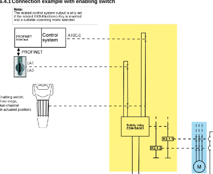
6.4.1 Connection example with enabling switch
Figure 3: Principle of operation (illustration with selected operating mode and all components in actuated position)
6.4.1.1 Description of the application example with enabling switch
The danger area on a machine is secured with a fence. To make set-up work on the machine possible with the safety door open, an EKS FSA system is integrated in conjunction with a control system, an enabling switch and a safety relay. The safety relay must comply with the following requirements:
Detection of short-circuits and earth faults. A short-circuit can be detected in the safety path in the circuit described due to the fact that both the positive path and earth path of the safety relay are switched. In this case, the safety relay deactivates its safety outputs.
Simultaneity monitoring: The safety relay must detect whether the safety inputs are switched practically simultaneously. If this is not the case, the safety outputs are not switched and the unit switches to fault state. A renewed start is possible only after the enabling switch has been released and then operated again.
The switching contact LA1/LA2 is closed after the insertion of the Electronic-Key. The EKS FSA is coupled with a control system. After the insertion of the Electronic-Key, the control system checks whether the key is
authorized for work in the selected operating mode. If this is not the case, the operating mode cannot be set. If suitable access rights are available, the control system gives the instruction to the switching contact A100.0 to close.
The switching contact LA1/LA2, in series with a switching contact on the enabling switch, is connected to the first input on the safety relay. The switching contact A100.0 is connected to the second input on the safety relay in series with the second switching contact on the enabling switch. The result is that these inputs on the safety relay are only enabled if
the EKS FSA (switching contact LA1/LA2) and
the control system (switching contact A100.0) issue the related enabling signal and
the enabling switch is actuated.
The output contacts on the safety relay are enabled only after actuation of the enabling switch.
The safety relay is de-energized without a time delay (stop category 0) and the machine movement is stopped if
the Electronic-Key is removed or
the enabling switch is released or
the machine control system cancels the enable state (contact A100.0 is opened).
Note: The control system output A100.0 is only allowed to be set if
the related Electronic-Key is inserted and
a suitable operating mode is selected.
Information!
The control system output A100.0 is only allowed to be set if
the related Electronic-Key is inserted and
a suitable operating mode is selected.
6.4.1.2 Feedback loop
The safety relay can be started only with the feedback loop closed. A welded contactor contact in the enable path will thus be detected when a start request is made and a start is then prevented. The power contactor must have positively driven contacts.
6.4.1.3 Start
The safety relay start takes place after enabling by the EKS FSA and by the control system and after operation of the enabling switch.
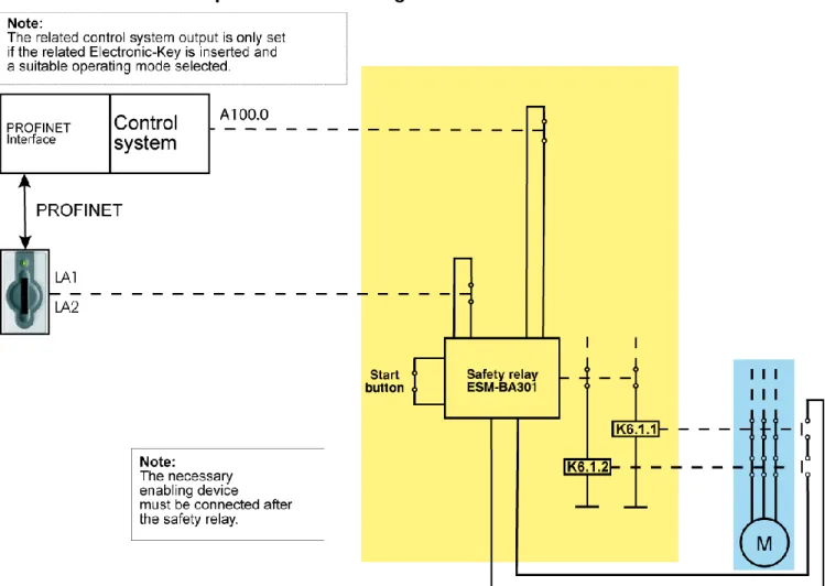
6.4.2 Connection example without enabling switch
Figure 5: Principle of operation (illustration with selected operating mode and all components in actuated position)
6.4.2.1 Description of the application example without enabling switch
The danger area on a machine is secured with a fence. To make set-up work on the machine possible with the safety door open, an EKS FSA system is integrated in conjunction with a control system and a safety relay. The safety relay must comply with the following requirements:
Detection of short-circuits and earth faults. A short-circuit can be detected in the safety path in the circuit described due to the fact that both the positive path and earth path of the safety relay are switched. In this case, the safety relay deactivates its safety outputs.
Simultaneity monitoring: The safety relay must detect whether the safety inputs are switched practically simultaneously. If this is not the case, the safety outputs are not switched and the unit switches to fault state. A renewed start is possible only after the key has been inserted again.
Start button monitoring: The safety relay must detect when the start button is welded or jammed at the latest at the next start. If this is the case, the safety outputs are not switched and the unit switches to fault
The safety relay is de-energized without a time delay (stop category 0) and the machine movement is stopped if
the Electronic-Key is removed or
the machine control system cancels the enable state (switching contact A100.0 is opened).
Information!
The switching contact A100.0 is only allowed to be set if
the related Electronic-Key is inserted and
a suitable operating mode is selected.
6.4.2.2 Feedback loop
The safety relay can be started only with the feedback loop closed. A welded contactor contact in the enable path will thus be detected when a start request is made and a start is then prevented. The power contactor must have positively driven contacts.
6.4.2.3 Start
The safety relay start takes place after enabling by the EKS FSA and by the control system and after operation of the start button.
7 Setup
Information!
You will require the corresponding GSD file in GSDML format to integrate the EKS in a PROFINET system environment:
GSDML-Vx.x-Euchner-EKS_109539-YYYYMMDD.xml
The GSD file is available in the Internet for download free of charge at www.EUCHNER.de or on request, order no. 109539. The archive with the GSD files also includes the image file eucoeks.bmp for depicting the Electronic-Key adapter in the configuration software.
Prior to commissioning, the GSD file must be imported into the configuration software for the control system (see control system manual).
For the PROFINET connection a separate switch or a crossover cable may be required.
Perform setup in the following sequence: 1. Configure EKS with the aid of the GSD file.
2. Set the DIP switches on the Electronic-Key adapter (see section 4.4).
3. Check mounting and electrical connection are correct (see section 5 and section 6).
4. After connection of the power supply, the LED on the front of the Electronic-Key adapter first illuminates red. When the connection has been established, the LED illuminates green and signals readiness for operation. 5. Insert Electronic-Key in the Electronic-Key adapter. The LED changes to yellow.
6. Important: for the version EKS FSA, all safety functions must also be thoroughly tested.
7.1 Requirements
You need the following hardware / software to integrate the EKS Electronic-Key adapter into the PROFINET network:
Current GSD file for the configuration
Configuration software (e.g. SIMATIC STEP 7)
7.2 Configuration settings
In this section the possible settings for the two modules EKS read and EKS write are described. In section 7.3 Connecting the EKS to a PROFINET CPU it is shown, step-by-step, how the device is configured in the configuration software for the control system.
Information!
On the usage of automatic name assignment in the control system based on the topology, the preset name in the device >>EKS-PN<< must be deleted first. This action can be undertaken, e.g., using the web interface or the SIMATIC STEP 7 software using >>Reset to factory settings<<.
7.2.1 Modules available in the GSD file for reading data
The number of bytes transferred cyclically is defined by the selection of the module in the GSD file. A maximum of 124 bytes user data can be read from the Electronic-Key. The following modules can be selected:
GSD file selection (data block size) Control system input area
Electronic-Key user data
read
Read: 009 bytes 8 bytes
Read: 017 bytes 16 bytes
Read: 033 bytes 32 bytes
Read: 065 bytes 64 bytes
Read: 128 bytes 124 bytes
The module selected defines the length of the data block that is read from the Electronic-Key and cyclically transferred to the input area. A larger data block occupies more memory in the input area of the control system.
Information!
The modules 009 bytes to 065 bytes can only be used on EKS Electronic-Key adapters from version 2.7.0 (August 2013) in conjunction with a GSD file from 2014 >>GSDML-V2.25-Euchner-EKS_109539-20140626.xml<< or >>GSDML-V2.3-Euchner-EKS_109539->>GSDML-V2.25-Euchner-EKS_109539-20140626.xml<<. The module 128 bytes is selected by default. The module 128 bytes can be used with all EKS Electronic-Key adapters. Earlier versions of the GSD file can be used with all Electronic-Key adapters.
7.2.2 Properties for the modules for reading data
A module EKS read reads alarms and Electronic-Key data and writes this information to the input area of the control system.
7.2.2.1 Parameter Alarm settings
Here it is defined how alarms that arise during reading are to be handled. The following settings are possible:
Activate diagnostics alarm
Activate process alarm
7.2.3 Modules available in the GSD file for writing data
The number of bytes transferred is defined by the selection of the module in the GSD file. A maximum of 116 bytes user data can be written to the Electronic-Key. The following modules can be selected:
GSD file selection (data block size) Control system output area
Electronic-Key user data
write
Write: 012 bytes 8 bytes
Write: 020 bytes 16 bytes
Write: 036 bytes 32 bytes
Write: 068 bytes 64 bytes
Write: 128 bytes 116 bytes
The module selected defines the length of the data block that is written to the Electronic-Key. A larger data block occupies more memory in the output area of the control system.
Information!
The modules 012 bytes to 068 bytes can only be used on EKS Electronic-Key adapters from version 2.7.0 (August 2013) in conjunction with a GSD file from 2014 >>GSDML-V2.25-Euchner-EKS_109539-20140626.xml<< or >>GSDML-V2.3-Euchner-EKS_109539->>GSDML-V2.25-Euchner-EKS_109539-20140626.xml<<. The module 128 bytes is selected by default. The module 128 bytes can be used with all EKS Electronic-Key adapters. Earlier versions of the GSD file can be used with all Electronic-Key adapters.
7.2.4 Properties for the modules for writing data
A module EKS write writes the data from the output area of the control system to the Electronic-Key.
7.2.4.1 Parameter Alarm settings
Here it is defined how alarms that arise during writing are to be handled. The following settings are possible:
Activate diagnostics alarm
Activate process alarm
7.3 Connecting the EKS to a PROFINET CPU
The integration of the EKS PROFINET (order no. 106305) is described in the following based on the example of the SIMATIC STEP 7 software and a Siemens CPU 315F-2 PN/DP.
1. Create a new S7 project.
2. Open the hardware configuration and install the current EKS GSD file.
3. Select the EKS from the catalog and drag it to the PROFINET system.
Information!
In the configuration software it is possible to integrate a single module for reading, or a single module for writing, or a module for reading and a further module for writing at the same time.
4. Select required module from GSD file
6. Make the alarm settings in the module EKS read.
7. In the module EKS read set the start address from which the data on the Electronic-Key are to be read.
10. Configure the required name for the EKS (default: EKS-PN)
11. If required, you can change the input address area in the control system for the module EKS read.
8 Operation in the PROFINET
8.1 Communication
This section primarily describes communication between a CPU and Electronic-Key adapter (referred to as the device in the following).
The communication between the control system and the device is either cyclic (write / read processes to and from the Electronic-Key) or acyclic (diagnostic messages).
8.2 EKS alarms
Depending on the setting in the configuration, the EKS can send
Diagnostics alarms
Process alarms
No alarms
to the control system (see section 7.2 Configuration settings).
Process alarms are written to a data area in the control system. The alarms have the following structure: [byte word with alarm no.];[byte with alarm information]
Example
During an attempt to read the serial number of the Electronic-Key, byte no. 116 is entered as the start byte and 20 bytes as the number of bytes to be read. However, in this case the maximum possible number of bytes is 8.
Description: Error during read access. Max. number of bytes allowed incorrect. Depiction in the related data area in the control system: 0100;08
Alarm no. Alarm information Description
0100hex Returns the max. number of bytes that are allowed
to be read.
Read process aborted. Max. number of bytes allowed exceeded.
0101 hex
Returns the max. number of bytes that are allowed to be written.
Write process interrupted. Max. number of bytes allowed exceeded.
0102 hex
Returns the number of bytes that has been entered incorrectly.
Write process interrupted. Number of bytes is not a multiple of the block size 4.
0103 hex Returns the start address that has been entered
incorrectly.
Write process interrupted. Start address is not a multiple of the block size 4.
0104 hex Not used Electronic-Key not in the operating distance.
0105 hex Not used General Electronic-Key communication error
(renewed write or read necessary).
0106 hex Not used Write attempt despite enabled write protection.
8.3 Read/write operation
In read or write operation, following successful configuration, a transfer message is continually transferred to the input area or from the output area of the control system during each I/O cycle.
The number of bytes transferred cyclically is defined by the selection of the module in the GSD file.
Information!
On the Electronic-Key read/write with 116 bytes freely programmable, the memory is organized in 4-byte blocks. This means the start address must be given for writing in the range 4-byte number 0 to 4-byte number 112, always in 4-byte steps (byte number 0, 4, 8 ... 112). Also a multiple of 4-byte sized blocks must always be written (4, 8, 12 ... 116 bytes)!
However, during reading it is possible to access the memory byte-by-byte without the above-mentioned restriction for writing.
The Electronic-Key read/write also contains a unique 8-byte serial number. This number is written by laser during the Electronic-Key production process and is hereby stored absolutely indestructibly. The serial number can therefore not be changed. The serial number is used for secure distinction of every single Electronic-Key. It is necessary that all 8 bytes are completely evaluated for secure distinction. The serial number is appended to the freely programmable memory. The serial number can be read by entering the start address byte number 116 and the number of bytes 8.
8.3.1 Input area (read process)
Information!
If a specific start address is not defined, the user data are cyclically transferred to the input area of the control system starting from byte no. 0 on the Electronic-Key. The number of bytes with user data transferred cyclically from the Electronic-Key depends on the setting in the configuration software for the control system (see section 7.2.2.2 Parameter Start address and 7.2.2.3 Parameter Number of bytes). Input area of the PROFINET CPU
Byte no. Description Function
0 Status byte (see below) 1
Receive data
Max. 124 bytes user data from the Electronic-Key plus 3 bytes reserve. If fewer bytes of data were selected during configuration, these are filled with 0hex.
: : 127
The following status information is transferred in the status byte (byte no. 0, see above): Status byte
Bit no. Description (active with bit = 1) Function
0 Electronic-Key adapter ready
After successful configuration the Electronic-Key adapter signals that it is ready via bit no. 0. Readiness should be continuously monitored by the application.
1 Electronic-Key detected The detection of a valid Electronic-Key is signaled using bit no. 1. Using this bit the application can detect that new data are available. 2
Reserve 3
8.3.2 Output area (write process)
Information!
When this command is used, the Electronic-Key must be in the Electronic-Key adapter, and must be removed from within the operating distance only after the reply message has been received.
As the serial number of the Electronic-Key cannot be written, the start address for the data to be written is limited to byte no. 0 to byte no. 112.
Output area of the PROFINET CPU
Byte no. Description Function
0 Command byte (see below) 1 Start address
Defines first byte in the memory of the Electronic-Key that is written on setting bit no. 0 in the command byte. Start address user data: Byte no. 0, 4, 8 … 112.
2 Number of bytes
Defines the number of bytes in the memory of the Electronic-Key that are written on setting bit no. 0 in the command byte. Number of bytes of user data: 4, 8, 12 … 116 bytes.
3 Not used 4
Transmit data
If bit no. 0 in the command byte is set to 1, the content of these bytes is written to the Electronic-Key starting from the start address defined. : : 119 120 : 127 Not used
In the command byte it is defined whether data are written to the Electronic-Key. Command byte
Bit no. Description (active with bit = 1) Function
0 Write Electronic-Key
After setting this bit the content of "Transmit data" is written to the Electronic-Key inserted, starting at the "Start address" with the length "Number of bytes". On the completion of the write process, bit no. 6 in the status byte in the input area of the CPU is set. Bit no. 0 in the command byte in the output area of the CPU must after this be set to 0 so that a new write process can be started.
1 Reserve 2 3 4 5 6 7 Information!
9 Analysis and assignment of DCP name via web interface
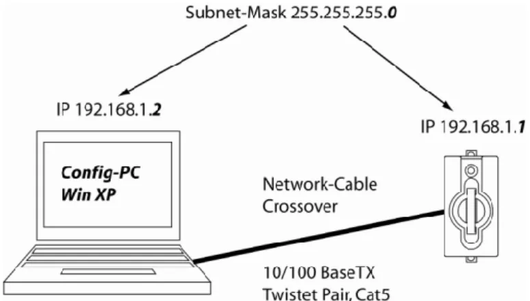
As an alternative to communication via PROFINET, it is possible to communicate with the EKS Electronic-Key adapter from a PC with the aid of web browser via TCP/IP. The feature can be used, e.g., for analysis, to read data from the memory in the Electronic-Key and to display them in the browser. The DCP name for the Electronic-Key adapter can also be set via the web browser (see also DIP switch settings in section 4.4.3). This process is described in detail in the following sections.9.1 Network settings for a configuration PC with Windows
®XP
Information!
It is assumed that you connect the PC to the EKS Electronic-Key adapter as shown in the following example.
For connection, you need a (Cat 5) patch cable with crossed cables (crossover).
You must first modify the network settings on the PC so that the web interface can be opened.
Enter IP address for the PC from 192.168.1.2 to 192.168.1.254.
Enter subnet mask for the PC as 255.255.255.0
Adapting network settings
1. Select Network Connections in your operating system.
2. Right-click Local Area Connection and then click Properties.
3. Check whether Internet Protocol (TCP/IP) is listed. If the entry Internet protocol (TCP/IP) is present, continue with Step 6.
4. Click Install. The Select network component type dialog box opens. Click Protocol and then click the
Add button. The Select network protocol dialog box opens.
5. In the Select network protocol dialog box, select the entry Microsoft TCP/IP and click OK. You may need the installation CD for Windows® XP to set this up.
6. In the Local Area Connection Properties dialog box, double-click the entry Internet Protocol TCP/IP. The
Internet Protocol (TCP/IP) Properties dialog box opens.
7. In order to ensure that the EKS Electronic-Key adapter and the configuration computer are in the same network, you must assign your configuration PC an IP address in the same subnet mask as the Electronic-Key adapter. On delivery, the default IP of the Electronic-Electronic-Key adapter is 192.168.1.1 and the subnet mask is 255.255.255.0. As a consequence you can allocate to the configuration PC, e.g., any IP address between 192.168.1.2 and 192.168.1.254. In this example, the configuration PC is assigned the IP address
192.168.1.2.
8. Click the OK button to confirm your inputs.
The EKS Electronic-Key adapter can now be configured via the integrated web interface as described in section 9.2.
9.2 Configuring the Electronic-Key adapter via the web interface
The Electronic-Key adapter can be configured with a web browser.
If you want to operate the Electronic-Key adapter with a self-defined DCP name, you can configure the device using a PC. A PROFINET control system is not required during this process. This is the fastest method, particularly if several devices have to be configured. The configuration PC must meet the following requirements:
Network card (10Base-T or 100Base-TX)
Web browser (e.g. Internet Explorer)
Java and Java Script must be activated in the security settings of the browser.
Java Runtime Environment in Version 1.5.0 or higher must be installed.
If the configuration PC features a firewall, it may be necessary to enable the EKS Electronic-Key adapter as a trustworthy application. Refer to the firewall documentation for further information.
Launching the EKS web interface
1. Open a browser window and enter the default IP address (http://192.168.1.1/). If necessary, first reset to the default IP address (see section 6.1.1.1).
2. Click Configuration.
The Configuration screen of the EKS web interface is now displayed.
1. Enter the required DCP name. 2. Click the Send button.
The following message is displayed: The settings were saved, to apply settings please switch power off/on…
3. Interrupt the power supply and connect the Electronic-Key adapter again in order to activate the settings.
Information!
9.3 Reading Electronic-Key data using the web interface
It is possible to view the serial number of the key and all the data stored on the key that is currently inserted in the key adapter by means of the web interface. The key data cannot be changed.
10 Exclusion of liability
Exclusion of liability under the following conditions:
incorrect use
non-compliance with safety regulations
if mounting and electrical connection are carried out by unauthorized personnel
if modifications are made
11 Service and repair
No servicing is required.
Remove dirt from the Electronic-Key and the Electronic-Key adapter using a soft cloth and solvent-free, non-abrasive cleaning agents.
Repairs must be performed only by the manufacturer.
On version EKS FSA devices, the safety-related functions must be checked at regular intervals.