Microstructure-Aided Digital Volume Correlation
H. Leclerc1,a, J.-N. P´eri´e2, A. Fanget3, E. Maire4, F. Hild1, and S. Roux1
1 LMT-Cachan, ENS Cachan/CNRS/UPMC/PRES UniverSud, 61 avenue du Pr´esident Wilson,
F-94235 Cachan Cedex, France
2 ICA (Institut Cl´ement Ader); Universit´e de Toulouse, INSA, UPS, Mines Albi, ISAE, 133 avenue
de Rangueil, F-31077 Toulouse, France
3 Centre d’Etudes de Gramat (CEA-DAM), F-46500 Gramat, France
4 Laboratoire Mat´eriaux, Ing´enierie et Sciences (MATEIS), INSA-Lyon/CNRS
7 avenue Jean Capelle, F-69621 Villeurbanne, France
Abstract. This paper describes how volumic images of a composite material could be
used to measure 3D displacement fields, and assess mechanical properties. The exemple
of a tensile test performed on a sample made of an energetic material is chosen. Different
tools are used, namely, X-ray microtomography of anin situexperiment, image
acquisi-tion and processing, volume correlaacquisi-tion to measure 3D displacement fields. The principle
of an integrated approach is finally introduced.
1 Introduction
Many biological tissues (e.g.,bones) and composite materials (e.g.,3D woven composites) exhibit
complex, coarse and nonperiodic microstructures. For such heterogeneous materials, classical
homog-enization techniques may not be applicable. The quest for microstructure dependent macroscopic
be-haviour and its identification are then a challenge [1]. The assessment of accurate local strains or stresses from a given macroscopic loading and some microstructural properties may also reveal to be
limiting.
The use of emerging 3D imaging techniques such as computed microtomography (CMT), offering a unique access to microstructural features, opens the way to new multiscale approaches. The example
of anin situtensile test performed on an energetic material is used. On the one hand, Finite Element
a e-mail:[email protected]
© Owned by the authors, published by EDP Sciences, 2010
(FE) models can be constructed directly from 3D images [2]. On the other hand, Digital Volume
Correlation may be used to measure 3D displacement fields in the bulk [3]. The analysis of mechanical
tests on energetic materials was already performed by using 2D Digital Image Correlation (DIC). The natural texture may be exploited to get macroscopic displacement fields [4],e.g.,to evaluate the
minimum size of a representative volume element [5]. A random pattern can also been sprayed onto the surface to determine in-plane displacements at the grain scale,e.g.,to analyze cracks [6]. To the
authors’ best knowledge, 3D analyses of such materials were never performed before.
Section 2 presents the material and the experimental setup. In Section 3, the basic principle of digital image based FE models is introduced. Some meshes automatically generated from the
refer-ence scan acquired are presented. In Section 4, a Galerkin approach to Digital Volume Correlation
(DVC) [7] is presented. It is used to measure 3D displacements and strain fields during a tensile test. The last section introduces the principal of anintegratedDVC approach, coupling global DVC and
Finite Element Model Updating. The proposed technique aims at regularizing measured displacement fields and identifying mechanical properties.
2 Material and experimental setup
Figure 1 shows a reference volume of the studied pressed energetic material. It is a two-phase compos-ite containing large stiffand brittle grains (i.e.,the aggregates) embedded in a compliant viscoelastic
binder (i.e.,the matrix). The tensile tests were performedin situat the European Synchrotron Radi-ation Facility, Grenoble, France (on beamline ID19). X-Ray microtomography enables 3D pictures
of the local density of solids to be obtained by exploiting the attenuation of a monochromatic X-ray
beam. The dynamic range of the reconstructed volumes (or scans) is equal to 8 bits, and the physical size of one voxel is 7.4μm. Six scans were acquired for the analyzed test. Apart from the reference
scan,i.e.,before any load was applied, three scans were taken up to the peak load and one thereafter (see figure 2). The last one is obtained after failure and is not analyzed herein.
Image and/or volume correlations require a random texture to measure displacements. The grains
are extremely helpful for the process, as they constitute a random marking with a high contrast dis-tributed within the specimen. As can be seen in Figure 1, they appear as white clusters with a well
defined morphology. The mean gray level is 157 and the corresponding standard deviation is 56, which
is a high value due to the bimodal distribution. The size of the reconstructed volumes is 20003voxels, and the analyzed volume of interest (VOI) is centered and has a restricted size because of memory
3 Digital image based micro FE modeling
Many Digital Image Based (DIB) approaches have been proposed [8, 9, 2, 10], especially in the field
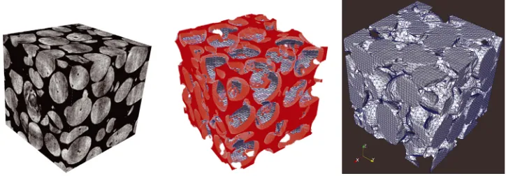
of biomechanics. For the two-phase material studied in this work and shown in Figure 1, one can for example resort to image segmentation in order to separate the matrix and the inclusions. An FE
model can then be automatically generated [11]. The mesh can either be regular (based on voxels) or unstructured (and based on tetrahedral elements). An automated procedure is used to mesh both
constituents [12] using tetrahedral elements (Figure 1). In such cases, the behaviour of an element only
depends on the local phase. However, the actual state and behaviour of the constituents can generally hardly be assessed (e.g.,because of a complex process) or are totally unknown (e.g.,in biological
tissues).
Fig. 1.Study of a polymer bonded particulate composite by using digital image based modeling. From left to
right: 1) Raw reference CMT image of the VOI; 2) Result of the segmentation and mesh associated with the
matrix; 3) mesh of the inclusions.
The identification of the microconstituentin situmechanical properties has to be performed
di-rectly from a macroscopic test performed on a composite specimen. Mean strains and forces may be measured, and, finally, an inverse problem is solved. The (micro)mechanical parameters are then
unknown while the microstructure and experimental (macro)quantities are known. This procedure is
fragile. Identification may be influenced by non representative boundary conditions or a poor DIB re-construction. An alternative route based on DVC measurements and suited to coarse microstructures
4 Finite Element Digital Volume Correlation
Volume correlation consists in registering the texture of two pictures (or scans in the present case) with
the help of a displacement field to be determined. To estimate the unknown displacement fieldU, the
quadratic differenceϕ2(X)=[f(X)−g(X+U(X))]2is integrated over the studied VOIΩ
Φ2=
Ωϕ
2(X)dX (1)
and minimized with respect to the degrees of freedom of the measured displacement field [7]. In
the present case, a 3D finite element kinematics is chosen [13] for the sought fields. The proposed technique is therefore a Galerkin approach to DVC. It allows for the decomposition of the displacement
field onto any meaningful or convenient basis,e.g.,a finite element basis (thus fully compatible with
the simulations and with DIB procedure). Other approaches to DVC can be found. Namely, as in 2D applications, the most commonly used correlation algorithms consist in registeringlocallysmall
sub-volumes in a sequence of pictures to determine local displacement components [15]. The same type of hypotheses are made in 3D algorithms [3, 16–18]. However, the present procedure cannaturallybe
coupled with FE simulation tools.
When dealing with structured meshes, simple shape functions may be used, namely, trilinear
poly-nomials associated with 8-node cube elements (or C8-DIC [7, 14]). When studying complex
geome-tries or microstructures, unstructured meshes based on tetrahedral elements are more relevant. An example of such mesh and the corresponding displacement field measured at the first step of
load-ing are presented in Figure 2. In that case, decreasload-ing the element size first induces a better local description of the displacement fields (checked by using residual mapsϕ(X)). However, very small
elements (typically smaller than grains) cannot be used since no relevant texture will be available, and
the measurement uncertainty would not allow for any reliable result to be found.
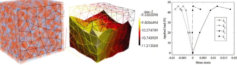
From the measured displacement fields, the strain fields are computed. In the present case, the
infinitesimal strain assumption cannot be made locally. Consequently, a large transformation frame-work is used. Mean strains over the whole cubic VOI are subsequently determined. Figure 2 presents
the change of averaged principal strains with respect to the applied load. An apparent Poisson’s ra-tioνcan be estimated in the chosen gauge volume. For the first three load steps, the corresponding Poisson’s ratios are 0.50,0.49,0.40. Up to the peak load, the value of the latter is virtually identical
and corresponds to that of an incompressible material. Beyond the peak load, it decreases, signaling displacement heterogeneities. In particular, the volumetric strainv = 1+2+3 remains vanish-ingly small except for the last analyzed level, where it becomes significantly positive (i.e.,dilatancy is
Fig. 2.Study of a polymer bonded particulate composite: FE-DVC using an unstructured mesh. From left to
right: 1) unstructured mesh used for DVC; 2) deformed mesh and corresponding displacement contours in the
tensile direction; 3) change of mean principaliand volumetric strainsv(over the meshed VOI) with the applied
macroscopic tensile load.
5 Conclusion and perspectives
As shown above, FE-DVC is a useful tool for investigating the multiscale behavior of materials ex-hibiting complex and coarse architectures. The technique also offers a great opportunity to compare
directly computed and measured displacement fields,i.e.,to retrieve macromechanical properties from full-field measurements [19]. A common identification technique consists in updating some
parame-ters of the FE model by comparing measured and computed kinematic fields (Finite Element Model
Updating or FEMU [20]). A convenient technique to deal with displacement fields consists in apply-ing measured displacement fields on the external surfaces of the volume of interest (VOI) as Dirichlet
boundary conditions in the FE simulation. The displacement fieldinsidethe VOI is then used to tune the constitutive parameters.
Unfortunately, especially in this case, the texture or contrasts inside the micro constituents are not
significant enough to assess accurately the micro kinematic field. One has also to remember that the
measured (by FE-DVC) and the computed displacement fields (DIB micro FE model) may not be comparable at the constituent scale. An alternative route has recently been proposed [21]. It consists
in using an integrated digital image correlation technique. The technique was first applied with 2D pictures to identify a Poisson’s ratio from a biaxial test. The idea is to exploitcomputeddisplacement
fields, which are meaningful from a mechanical standpoint, to register the reference image onto the deformed one. In practice, the method couples strongly FE-DVC with FEMU.
The approach is presently being tested on the presented energetic material. The displacement field basis used in the global DVC approach then results from a 3D simulation using the constructed (i.e.,
by FE-DVC measurements achieved by using a coarser mesh (the element size here is typically of the
order of the inclusion size, see Figure 2). This work is in progress.
References
1. B. Banerjee and D. O. Adams, Physica B: Condensed Matter338, (2003) 8-15. 2. S.J. Holister and N. Kikuchi, Biotechnology and Bioengineering43,(1994) 11
3. B.K. Bay, T.S. Smith, D.P. Fyhrie, M. Saad, Experimental Mechanics39, (1999) 10
4. P. J. Rae, S. J. P. Palmer, H. T. Goldrein, A. L. Lewis and J. E. Field, Optics and Lasers in
Engi-neering41, (2004) 635-648.
5. C. Liu, Experimental Mechanics45[3], (2005) 238-243.
6. M. Li, J. Zhang, C. Xiong, J. Fang, J. M. Li, and Y. Hao, Optics and Lasers in Engineering43[8],
(2005) 856-868.
7. S. Roux, F. Hild, P. Viot, D. Bernard, Composites Part A39, (2008) 495-508
8. S. C. Cowin, Mechanics of Materials4[2], (1985) 137-147.
9. J. Keyak, J. Meagher, H. Skinner, and C.D. Mote J., Journal of Biomedical Engineering12[5],
(1990) 389-397.
10. van Rietbergen, B., Weinans, H., Huiskes, R. and Odgaard, A., Journal of Biomechanics28, (1995) 69-81.
11. P. Young, T. Beresford-West, S. Coward, B. Notarberardino, B. Walker, and A. Abdul-Aziz, Philo-sophical Transactions of the Royal Society A: Mathematical, Physical and Engineering Sciences 366[1878], (2008) 3155-3173.
12. H. J. Kim and C. C. Swan, International Journal for Numerical Methods in Engineering58[11], (2003) 1683-1711.
13. O. C. Zienkievicz and R. L. Taylor,The Finite Element Method, (McGraw-Hill, London (UK), 4th edition, 1989).
14. A. Benoit, S. Gu´erard, B. Gillet, G. Guillot, F. Hild, D. Mitton, J. P´eri´e, and S. Roux, Journal of Biomechanics42[14], (2009) 2381-2386.
15. P. Cheng, M. A. Sutton, H. W. Schreier and S. R. McNeill, Experimental Mechanics42[3], (2002)
344-352.
16. T. S. Smith, B. K. Bay and M. M. Rashid, Experimental Mechanics42[3], (2002) 272-278.
18. E. Verhulp, B. van Rietbergen and R. Huiskes, Journal of Biomechanics37[9], (2004) 1313-1320. 19. S. Avril, M. Bonnet, A. Bretelle, M. Gr´ediac, F. Hild, P. Ienny, F. Latourte, D. Lemosse, S. Pagano,
E. Pagnacco, and F. Pierron, Experimental Mechanics48[4], (2008) 381-402.
20. K. T. Kavanagh and R. W. Clough, International Journal of Solids and Structures7, (1971) 13
21. H. Leclerc, J.-N. P´eri´e, S. Roux, F. Hild,Proceedings of the 4th International Conference on Com-puter Vision/Computer Graphics Collaboration Techniques, Lecture Notes In Computer Science