Available Online atwww.ijcsmc.com
International Journal of Computer Science and Mobile Computing
A Monthly Journal of Computer Science and Information Technology
ISSN 2320–088X
IJCSMC, Vol. 4, Issue. 10, October 2015, pg.40 – 45
RESEARCH ARTICLE
Performance Analysis of Optical Time Division
Multiplexing Using RZ Pulse Generator
Er. Tajinder Kaur
1, Er. Gaurav Soni
21,2Dept. of Electronics and Communication Engineering, Amritsar College of Engineering and Technology
M.Tech Research Scholar1, Associate Professor2 Amritsar, Punjab, India
Abstract - A communication system sends the signals from one place to another, whether separated by a few kilometers or by transoceanic distances. An electromagnetic carrier wave carried these signals with vary frequency from few megahertz to terahertz. Higher frequencies are used in optical communication systems. Optical communication is also called light wave systems. To send the optical signals from one place to another there is a need of channels. In light wave systems optical fibers are used as channels to send the signals because fibers can transmit light with losses as small as possible i.e. 0.2 dB/km. To increase the capacity of data signal to send from one place to another there is need of multiplexing. In optical communication two optical-domain techniques TDM and FDM kwon as optical TDM (OTDM) and wavelength-division multiplexing (WDM), respectively. In this paper, we design optimize link of OTDM at 40gbps on optisim 7 software. We show the performance of system by using different pulses with RZ pulse generator.
Keywords: optical communication, WDM, OTDM, RZ
I. INTRODUCTION
An optical communication system sends the signals from one place to another, whether separated by a few
kilometers or by transoceanic distances. An electromagnetic carrier wave carried these signals with vary
frequency from few megahertz to terahertz. Higher frequencies are used in optical communication systems.
Optical communication is also called light wave systems. To send the optical signals from one place to another
there is a need of channels. In optical communication two optical-domain techniques TDM and FDM kwon as
optical TDM (OTDM) and wavelength-division multiplexing (WDM), respectively [1].TDM is commonly
performed in the electrical domain to obtain digital hierarchies. In this sense, even single channel lightwave
systems carry multiple TDM channels. The electrical TDM becomes difficult to implement at bit rates above 10
Gb/s because of the limitations imposed by high-speed electronics. A solution is offered by the optical TDM
(OTDM), a scheme that can increase the bit rate of a single optical carrier to values above 1 Tb/s. The OTDM
technique was studied extensively during the 1990s [2]–[7]. Its commercial deployment requires new types of
optical transmitters and receivers based on all optical multiplexing and demultiplexing techniques [8]. WDM
corresponds to the scheme in which multiple optical carriers at different wavelengths are modulated by using
domain) and are then transmitted over the same fiber. The optical signal at the receiver is demultiplexed into
separate channels by using an optical technique [9]. In this paper firstly we give an overview on WDM and
OTDM, after that we discussed about the design of OTDM optical link and at last we give the results and
conclusion of this research work.
II. WAVELENGTH DIVISION MULTIPLEXING (WDM) SYSTEMS
WDM corresponds to the scheme in which multiple optical carriers at different wavelengths are modulated by
using independent electrical bit streams (which may themselves use TDM and FDM techniques in the electrical
domain) and are then transmitted over the same fiber. The optical signal at the receiver is demultiplexed into
separate channels by using an optical technique. WDM has the potential for exploiting the large bandwidth
offered by optical fibers. For example, hundreds of 10-Gb/s channels can be transmitted over the same fiber
when channel spacing is reduced to below 100 GHz. The concept of WDM has been pursued since the first
commercial lightwave system became available in 1980 [10].WDM systems first appeared around 1995, and
their total capacity exceeded 1.6 Tb/s by the year 2000. Several laboratory experiments demonstrated in 2001 a
system capacity of more than 10 Tb/s although the transmission distance was limited to below 200 km. Clearly,
the advent of WDM has led to a virtual revolution in designing lightwave systems [11].
Fig.1.Multichannel point to point fiber link. Separate transmitter-receiver pairs are used to send and receive the signal at different wavelengths [11]
For long-haul fiber links forming the backbone or the core of a telecommunication network, the role of WDM is
simply to increase the total bit rate [11]. Figure 1 shows schematically such a point-to-point, high-capacity,
WDM link. The output of several transmitters, each operating at its own carrier frequency (or wavelength), is
multiplexed together. The multiplexed signal is launched into the optical fiber for transmission to the other end,
where a demultiplexer sends each channel to its own receiver. WDM systems are good but there are so many
system performance issues like inter channel crosstalk, non linear cross talk. Another major issue in the design
of WDM systems concerns dispersion management [11]. So because of these issues we use the OTDM, also we
use hybrid of WDM and OTDM for communication systems.
III. OPTICAL TIME DIVISION SYSTEM (OTDM) SYSTEMS
OTDM (Optical Time Division Multiplexing) is a powerful multiplexing technique that provides very high
capacity of data transmission over optical fiber. In OTDM networks, several lower bit-rate optical streams are
time-multiplexed to generate a high bit-rate data stream. Likewise, at the receiver side of the system, the high
several optical signals at a bit rate B share the same carrier frequency and are multiplexed optically to form a composite bit stream at the bit rate NB, where N is the number of channels [2]. Figure 2 shows the design of an OTDM transmitter based on the delay-line technique. It requires a laser capable of generating a periodic pulse
train at the repetition rate equal to the single-channel bit rate B. Moreover, the laser should produce pulses of
width Tp such that Tp < TB = (NB)−1 to ensure that each pulse will fit within its allocated time slot TB. The
laser output is split equally into N branches, after amplification if necessary. A modulator in each branch blocks
the pulses representing 0 bits and creates N independent bit streams at the bit rate B.
Fig. 2: Design of an OTDM transmitter based on optical delay lines.[2]
Multiplexing of N bit streams is achieved by a delay technique that can be implemented optically in a simple
manner. In this scheme, the bit stream in the nth branch is delayed by an amount (n−1)/(NB), where n = 1, . . .
,N. The output of all branches is then combined to form a composite signal. It should be clear that the
multiplexed bit stream produced using such a scheme has a bit slot corresponding to the bit rate NB.
Furthermore, N consecutive bits in each interval of duration B−1 belong to N different channels, as required by
the TDM scheme. Demultiplexing of individual channels from an OTDM signal requires electro-optic or
all-optical techniques. Several schemes have been developed, each having its own merits and drawbacks. All
demultiplexing techniques require a clock signal—a periodic pulse train at the single-channel bit rate. There are
mainly three types of demultiplexing schemes used i.e. (a) cascaded LiNbO3 modulators, (b) XPM in a
nonlinear optical-loop mirror, and (c) FWM in a nonlinear medium.
IV. SIMULATION SETUP
In this paper, the performance of OTDM system has been evaluated for different bit rates and lengths of SMF
with different pulse generators like RZ and NRZ. The four channels OTDM system is shown in Figure (3). A
CW laser diode with a frequency of 193.1 THz (1552 nm) has used. The splitter divides the optical power
between the four channels. Each channel consists of a PRBS generator at a specific rate and an External
amplitude modulator. In each channel there has a time delay with time with different values 0ns, 2 ns, 4ns, 6ns
respectively So each user capable of transmitting information at a specific time slot. After that with the help of
optical power combiner the signal is combined and sent through a single mode fiber SMF. Here in the
transmission link there are EDFA amplifier is used. They are used as pre, post and inline amplifiers which are
used to improve the signal quality and to reduce the noise effect in the signal. Dispersion compensation fiber is
also used to reduce the dispersion effect into the fiber. DCF has an attenuation 0.3 dB/km, dispersion −80
L1N1+L2N2=0 (1)
Where ―L1 is length of SMF, N1 is dispersion of SMF,
L2 is length of DCF, N2 is dispersion of DCF‖
According to equation 1, length of DCF and SMF is taken. After the signal transmitted through the transmission
link, it is demultiplex by Demux. On the receiver side the signal is send to the Photo detector pin, low pass filter
bessel and clock recovery. Filter is used to filter the signal noise and cock recovery is used for time
synchronization. Then the BER is used to analyze. From the eye diagram we collect the results of the system.
Fig.3. simulation setup of OTDM
In this set up we get the results of different pulse shapes with using different pulse generators. We show the
different pulses like sine, Gaussian, linear and exponential wave behaviour with RZ pulse generator. The
various parameter used in this simulation work are shown in table no 1.
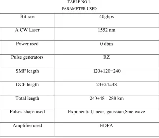
TABLE NO 1. PARAMETER USED
Bit rate 40gbps
A CW Laser 1552 nm
Power used 0 dbm
Pulse generators RZ
SMF length 120+120=240
DCF length 24+24=48
Total length 240+48= 288 km
Pulses shape used Exponential,linear, gaussian,Sine wave
V. RESULTS AND DISCUSSION
From the table no. 2, it is clear that the gaussian pulse give the better performance as compare to the
exponential, linear and sine wave pulses. The value of quality facor of all its channel is better as compare to all
other channels of exponential, linear,and sine wave pulses.
TABLE NO. 2
Q - FACTOR OF DIFFERENT PULSE SHAPES OF EAM AT LASER POWER 0 dbm WITH RZ .
Pulse shape Channel 1 Channel 2 Channel 3 Channel 4
Exponential-RZ 12.49 13.32 12.78 11.75
Gaussian-RZ 12.72 13.48 12.85 11.92
Linear-RZ 12.58 13.46 12.90 11.88
Sine-RZ 9.82 10.63 10.01 9.47
TABLE NO. 3
Q - FACTOR OF ALL CHANNELS WITH FIBER LENGTH AT LASER POWER 0 dbm WITH RZ .
Channels/Fiber Length
348 KM 354 KM 360 KM 366 KM
Channel 1 9.33 9.59 15.24 10.60
Channel 2 10.43 9.75 14.09 9.79
Channel 3 10.29 10.53 14.14 10.91
Channel 4 10.08 9.86 12.63 10.29
In table no. 3 we show the results of four channels with correspondence fiber length. All results had been
showed the values at 0 dbm power. We improve the link length from 348 km to 366 km. It gives the better
quality factor at 360 km as shown in table no 3.
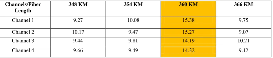
Table no. 4
Q - FACTOR OF ALL CHANNELS WITH FIBER LENGTH AT LASER POWER 2 dbm with RZ .
Channels/Fiber Length
348 KM 354 KM 360 KM 366 KM
Channel 1 9.27 10.08 15.38 9.75
Channel 2 10.17 9.47 15.27 9.07
Channel 3 9.44 9.81 14.19 10.21
Channel 4 9.66 9.49 14.32 9.12
In table no. 4 we show the results of four channels with correspondence fiber length. All results had been
showed the values at 2 dbm power. We improve the link length from 348 km to 366 km. It gives the better
quality factor at 360 km as shown in table no 3.
VI. CONCLUSION
In this study, the RZ pulse generator is used in the above simulation work. This work shows the quality factor of
different pulses of RZ pulse generator. To get the better results Gaussian pulse perform better as compared to
other as shown in table no 2. Table no 3 and table no 4 shows that with increase the fiber length the values of
conclude that with increase the power of laser we get the better results. With 2 dbm laser power we get better
quality factor. So laser power was an important parameter in simulation work. According to OFC standards the
quality factor 5 and more that 5 is best quality factor. In this work we get the 11.84 quality factor at link length
360 km at data rate 40 gbps, which is a good achievement.
REFERENCES
1. Lange, D. Kosiankowski, R. Weidmann, A. Gladisch: ‗Energy Consumption of Telecommunication Networks and Related Improvement Options‘, Journal of Selected Topics in Quantum Electronics,
17(2), 2011.
2. H. A. Mohammed: ‗Optical Time Division Multiplexing (OTDM) and Hybrid WDM/OTDM PON Performance Investigation‘, ISSN, 4(3), pp. 2278-4209, 2013.
3. H. Weber, R. Ludwig, S. Ferber, C. Schmidt-Langhorst, M. Kroh, V. Marembert, C. Boerner, C.
Schubert: ‗Ultrahigh-Speed OTDM-Transmission Technology‘, Journal of Lightwave Technology,
24(12), 2006.
4. J. Ahamed, G. Qazi, M. Ah:‘ Investigation of Sensitivity of Performance to Pulse Shapes in OTDM
System‘, Association of Computer Electronics and Electrical Engineers, 2013.
5. R. S. Tucker, R. Parthiban, J. Baliga, K. Hinton, R. W. A. Ayre, W. V. Sorin: ‗Evolution of WDM
Optical IP Networks: A Cost and Energy Perspective‘, Journal of Lightwave Technology, 27(3), 2009.
6. J.P. Ryan, ―WDM: North American deployment trends,‖ IEEE Comm. Mag., pp. 40-44 February, 1998.
7. Jing Xu, Christophe Peucheret, Palle Jeppesen, ―Power consumption comparison between
point-to-point WDM and OTDM systems, transparent Optical Networks (ICTON), International Conference on
digital object identifier, pp. 1-4, 2010.
8. J.P. Ryan, ―WDM: North American deployment trends,‖ IEEE Comm. Mag., pp. 40-44, February, 1998.
9. A. E. Willner, Z. Pan, M. I. Hayee, ―Major Accomplishments in 2010 on Optical Fiber Communication,‖ IEEE Photonics Journal, Vol. 3, No. 2, pp. 320-324, April 2011.
10. A. Singha, A. K. Sharmab, S. Singh, P. Singh: ‗Performance analysis of OTDM system in the presence
of FEC using symmetric Mach-Zehnder switch, Optik’, 121 pp. 326-329, 2010.
11. Jyotsana, R. Kaur, R. Singh: ‗Simulative Comparison of 40 Gbps OTDM Transmission System
![Fig. 2: Design of an OTDM transmitter based on optical delay lines.[2]](https://thumb-us.123doks.com/thumbv2/123dok_us/1938377.1254746/3.595.143.451.194.332/fig-design-otdm-transmitter-based-optical-delay-lines.webp)