127 |
P a g e
COMPARATIVE STUDY OF COMPOSITE
STRUCTURE
Nitin m. Warade
Department of Civil Engineering, PLITMS, Buldhana
ABSTRACT
This paper deals with the study of composite structure as compare with the concrete and steel structure. The
composite structure is far more advantageous over steel and concrete structure regarding Strength, Costs, and
Time Period requirements. There is no need for formwork because the steel beam is able to sustain the self
weight of steel and concrete, by itself or with the assistance of a few temporary props. Also Composite Structure
behaves more better in seismic condition and in case of thermal expansion in steel. These beneficial properties
such as load carrying capacity, cost of a single beam, erection time can be achieved by mere use of mandatories
in composite structure during construction.
Keywords: Composite Beam
,
Composite Column, Composite Action in Beam, Seismic Design.
I INTRODUCTION
The most important and most frequently encountered combination of construction materials is that of steel and
concrete, with applications in multi-storey commercial buildings and factories, as well as in bridges. These
materials can be used in mixed structural systems, for example concrete cores encircled by steel tubes, as well as
in composite structures where members consisting of steel and concrete act together compositely.
These essentially different materials are completely compatible and complementary to each other; they have
almost the same thermal expansion; they have an ideal combination of strengths with the concrete efficient in
compression and the steel in tension; concrete also gives corrosion protection and thermal insulation to the steel
at elevated temperatures and additionally can restrain slender steel sections from local or lateral-torsional
buckling. The purpose of this work is to introduce steel-concrete composite members and construction: to
explain the composite action of the two different materials ,to show how the structural members are
used ,particularly in building construction and there advantage over concrete and steel structures ,to give a brief
introduction to composite building structure ;to describe the elements, the connections ,the fabrication and the
interaction of the elements ;and to discuss the structural systems used.
In multi-storey buildings, structural steelwork is typically used together with concrete; for example, steel beams
with concrete floor slabs. The extent to which the components or parts of a building structure should embody all
steel construction or constructed entirely in reinforced concrete or be of composite construction depends on the
circumstances. It is a fact, that engineers are increasingly designing composite and mixed building systems of
structural steel and reinforced concrete to produce more efficient structures when compared to designs using
128 |
P a g e
It should be added that the combination of concrete cores, steel frame and composite floor construction has
become the standard construction method for multi-storey commercial buildings in several countries. Much
progress has been made, for example in Japan, where the structural steel/reinforced concrete frame is the
standard system for tall buildings. The main reason for this preference is that the sections and members shown
in image 1 are best suited to resist repeated earthquake loadings, which require a high amount of resistance and
ductility.
Fig1: The combination of concrete cores, steel frame and composite floor
In addition any structural system is usually subject to the following constraints. It should: conform to the
architectural requirements and those of the user or owner. Facilitate the service systems, such as heating,
ventilation and air conditioning, horizontal and vertical cabling, and other electrical and mechanical systems.
Facilitate simple and fast erection of the building, have adequate resistance to fire, enable the building,
foundation and ground to interact properly and most important be economical.
Steel-concrete composite systems for buildings are composed of concrete components that interact with
structural steel components within the same system. By their integral behavior, these components give the
required attributes of strength, stiffness and stability to the overall system. Composite members, as individual
elements of systems, have been in use for a considerable number of years. They consist of composite beams or
trusses, encased or filled composite columns, and steel deck reinforced composite slabs. These members are
generally used in steel structures, and their development as composite members is based on utilizing the
concrete that would normally be required for floor slabs with steel beams or that would be required for fire
protective encasements with steel columns.
1.1.
Advantages of composite structure
Composite floor construction used for commercial and other multi-storey buildings, offers the following main
advantages to the designer and client;
129 |
P a g e
Lighter construction than a traditional concrete building (structural steel and lightweight concrete,slender structural elements of small dimensions).
Less on site construction (steelwork, prefabricated structural elements).
Small (strict) tolerances achieved by using steel members manufactured under controlled factory
conditions to established quality procedures.
1.2. Types of composite system
The following composite systems have been used for a wide range of buildings:
1. Frame structure: Frame structures can be either rigid or flexible, depending on the relative rigidity of
beams with respect to columns. In the case of a rigid system, both these elements are connected to each
other rigidly to transmit lateral loads to the foundation. In addition, slabs provide transverse stiffness to
the entire system at the floor levels.
2. Shear wall structure: Within the preceding frame structure, a system of shear walls may be provided
in the direction of lateral forces to help transmit them to the foundation. The shear walls typically
surround certain services, such as elevators or stairs, and so serve a doubly useful purpose. A suitable
combination of shear wall and frame system can serve as a very useful load transmitting system for
both vertical and horizontal forces. However, for certain cases, the need for adequate ductility must be
investigated.
3. Staggered shear wall system: Shear walls in this system are staggered from floor to floor. The walls
support floors both above and below, and by virtue of staggering they can help create the large open
areas needed in a commercial building.
4. Tubular system: The tubular system combines characteristics of the preceding three systems. It acts as
a rigid but perforated tube, which, by means of its monolithic action and rigidity, transmits both the
transverse and vertical forces to the foundation. Depending on the height of the building, the shear wall
(as a core) may be combined with the external tube structure. This is known as a "frame - tube"
structure.
1.3. Seismic Design
Seismic design of a building structure requires that all parts of it respond nearly simultaneously when subjected
to ground motion. Therefore, when earthquake forces must be considered, their effects on all building
components must be evaluated. In evaluating these effects, it must be remembered that earthquake motions are
random, and occur both horizontally and vertically. The earthquake response of steel and composite building
structures is a subject of much interest, because local buckling of the compression flange is inhibited (by the
shear connection between the steel and concrete slab), and resistance to lateral buckling is greatly increased.
Furthermore, concrete-filled tubes and encased rolled sections possess much higher shear resistance than
reinforced concrete columns of the same size. High shear resistance is very important for seismic structures and
130 |
P a g e
1.4. Building Components
Every building, whether it is large or small, must have a structural system capable of carrying all kinds of loads
- vertical, horizontal, temperature, etc. In principle, the entire resisting system of the building should be equally
active under all types of loading. In other words, the structure resisting horizontal loads should be able to resist
vertical loads as well and many individual elements should be common to both types of systems.
II FLOOR STRUCTURES
Floor structures are responsible for a large percentage of the cost of buildings. They can be built using elements
of steel and reinforced concrete in various combinations. Structural floor systems are, of course, influenced by
the material used, but in all cases they are a combination of slabs and main or secondary beams. The
characteristic element, for the whole floor structure is the floor slab whose thickness and reinforcement is
dependent upon the span, the loading and the support conditions.
In floor construction, the use of the solid reinforced concrete slab is being replaced more and more by metal
decking, see Figure 1. Modern profiled steel sheeting with additional indentations or embossments act as both
permanent formwork during concreting and tension reinforcement after the concrete has hardened. At this final
stage the composite slab consists of a profiled steel sheet and an upper concrete topping which are
interconnected in such a manner that horizontal shear forces can be resisted at the steel-concrete interface. Slip
(relative displacements) at the interface must be prevented completely or partly, so that vertical separation of the
steel decking from the concrete topping
Fig 2. Use of Metal Decking in a Floor
The spanning capability of the construction can be extended by increasing the slab depth but this increases the
weight of construction and the depth of the floor beams. The overall depth of the floor system is therefore
determined by a balancing of factors. Experience has shown that the most efficient floor arrangements are those
using metal decking as permanent shuttering spanning 2.5 – 3.5 m between floor beams. For these spans the
metal decking does not normally require propping during concreting and the concrete thicknesses are near the
131 |
P a g e
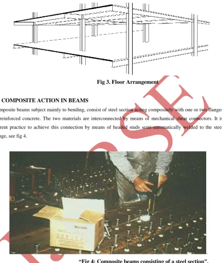
Fig 3. Floor Arrangement
III COMPOSITE ACTION IN BEAMS
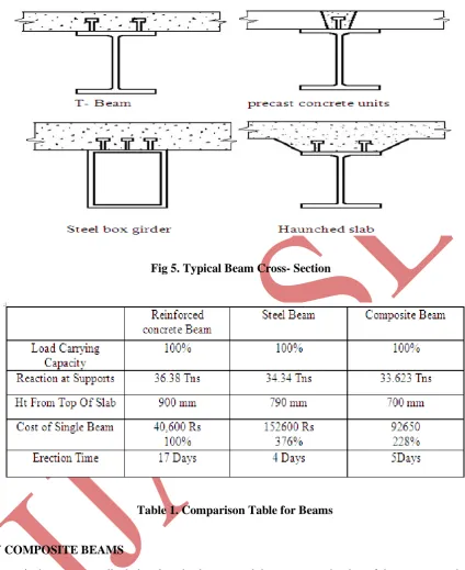
Composite beams subject mainly to bending, consist of steel section acting compositely with one or two flanges
of reinforced concrete. The two materials are interconnected by means of mechanical shear connectors. It is
current practice to achieve this connection by means of headed studs semi-automatically welded to the steel
flange, see fig 4.
.
“Fig 4: Composite beams consisting of a steel section”.
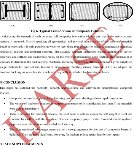
Figure 5. shows several composite beam cross-sections (rolled or welded sections) in which the wet concrete has
been cast in situ on timber shuttering. For single span beams, sagging bending moments due to applied vertical
loads cause tensile forces. in the steel section and compression in the concrete deck thereby making optimum
use of each material. Therefore composite beams even with small steel sections have high stiffness and can
132 |
P a g e
Fig 5. Typical Beam Cross- Section
Table 1. Comparison Table for Beams
IV COMPOSITE BEAMS
Composite beams are usually designed as simply supported, i.e. no account is taken of the moment continuity
provided by the beam-to-column or beam-to-beam connections. This approach is used mainly because it gives
ease of design and construction. It is also adopted partly because adequate structural performance can be
achieved readily by developing composite
action
alone. This result certainly holds good for beam spans of 6mto 10m which form the major part of work thesedays.
V COMPOSITE COLUMNS
Three different types of composite columns are principally in use, see Figure 4.
133 |
P a g e
Concrete filled steel tubes and (c and d) Rolled section columns partly encased in concrete (b).
Fig 6. Typical Cross-Sections of Composite Columns
In calculating the strength of such columns, full composite interaction without any slip at the
steel-concrete-interface is assumed. Strictly speaking all geometrical and physical non-linearity of the different materials
should be observed. It is only possible, however to meet these requirements by using comprehensive numerical
methods of analysis and computer software. The assumed complete interaction enables definition of section
properties, and stiffness and slenderness ratios, for the whole inhomogeneous cross-section. This information is
necessary to determine the load carrying resistance, including slenderness effects. Eurocode 4 gives simplified
design methods for practical use. Instead of more precise buckling curves, Eurocode 4 [1] has adopted the
European buckling curves a, b and c which were originally established for bare steel columns
VI CONCLUSION
This paper has outlined the necessity, concept, and favorable and unfavorable circumstances composite
structure.
Composite construction, particularly that using profiled steel sheeting, allows rapid construction.
The weight of steelwork required in composite construction is significantly less than if the materials
were used independently.
There is no need for formwork because the steel beam is able to sustain the self weight of steel and
concrete, by itself or with the assistance of a few temporary props. Timber formwork can be replaced
by precast concrete elements or profiled steel sheeting.
The aforementioned advantages present a very strong argument for the use of composite beams in
buildings. They are more significant, however, for medium to long spans than for short spans.
VII ACKNOWLEDGEMENTS
Here I take this opportunity to thank all those who have directly or indirectly contributed in the successful completion of this paper. I am
thankful to Asst. Prof. P.J.SALUNKE for their valuable guidance and encouragement throughout the completion of my work.
REFERENCES
Books:
[1] JONSON R.P. “composite structures of Steel and Concrete”; Volume 1: Beams, Columns, Frames and
134 |
P a g e
[2] JONSON, R.P.,Composite Construction 1 and 2.[3] LAWSON, R.M, “Design of Composite Slabs and Beams with Steeel Decking”, SCI-publication 055,
1989.
[4] LAWSON, R.M. and Rackham.J. “Design of haunched composite beams”. The Steel Construction
Institute,1989.
[5] Hart,F., Henn,W., Sontag H., “Multi-Storey Building in Steel” .Second Edition, Collins, London 1985.
IS Codes:
[6] Eurocode 4: “Design of composite steel and concrete structures” :ENV 1994-1-1: part 1.1 : General
rules and rules for buildings.
[7] IS-3935-1996 Code of practice for Composite Construction.
[8] IS-11384-1985 Code of Practice for composite Construction in Structural Steel and Concrete.
.