NREPO: Normal Basis Recomputing with Permuted Operands
Xiaofei Guo1, Debdeep Mukhopadhyay2, Chenglu Jin1, and Ramesh Karri1
1
Dept. of Electrical and Computer Engineering New York University School of Engineering
{xg243, cj875, rkarri}@nyu.edu 2
Dept. of Computer Science and Engineering Indian Institute of Technology Kharagpur
Abstract. Hardware implementations of cryptographic algorithms are vulnerable to natural and malicious faults. Concurrent Error Detection (CED) can be used to detect these faults. We present NREPO, a CED which does not require redundant computational resources in the design. Therefore, one can integrate it when computational resources are scarce or when the redundant resources are difficult to harness for CED. We integrate NREPO in a low-cost Advanced Encryption Standard (AES) implementation with 8-bit datapath. We show that NREPO has 25 and 50 times lower fault miss rate than robust code and parity, respectively. The area, throughput, and power are compared with other CEDs on 45nm ASIC. The hardware overhead of NREPO is 34.9%. The throughput and power are 271.6Mbps and 1579.3µW, respectively. One can also implement NREPO in other cryptographic algorithms.
1
Introduction
The Advanced Encryption Standard (AES) is used in a variety of applications, including smart cards, mobile phones, sensors, and other embedded systems. The decreasing cost of VLSI chips and increasing user throughput requirements make hardware implementation of AES necessary.
In embedded systems such as sensors, medical devices, and radio frequency identification tags (RFID), cost can be a significant constraint. To reduce the area and power, 32- or 8-bit instead of 128-bit AES datapath can be implemented [11, 14]. AES processes each byte with a substitution-box (S-box) which consumes the largest area [11]. One can reduce the S-box size by transforming its operations to a composite field with polynomial basis, normal basis, or mixed bases. The smallest AES S-boxes use normal basis [8, 23]3.
Although AES is difficult to break mathematically, its hardware implementations may contain security vulnera-bilities. An attacker can inject malicious faults into a cryptographic device and build correlations between the faulty and the corresponding fault-free outputs to extract the key in a short time. This is known as differential fault analy-sis (DFA) [5]. DFA has been shown by injecting transient faults using clock glitches [2] and by lowering the supply voltage [17]. An attackers may also inject faults with lasers [7] and electromagnetic pulse [9].
Concurrent error detection (CED) can be used against DFA. Hardware redundancy duplicates the hardware and detects faults by comparing the outputs. Time redundancy computes the input twice on the hardware and compares the results [7]. Information redundancy uses error detecting codes [18, 19, 21]. Hybrid redundancy uses algorithm properties [12, 16, 24].
Hardware redundancy is not affordable when area is the limitation. Time redundancy is vulnerable to same faults injected in both the computation and recomputation [7]. Parity is low-cost, but provides limited defence against DFA [9]. One example hybrid redundancy [16] has large overhead if a cipher uses counter mode, output feedback mode, or cipher feedback mode because only encryption or decryption is needed [26]. Another example hybrid redundancy [24] shares hardware between encryption and decryption and interleaves the encryption and decryption operations in time. But such sharing is difficult and requires many registers to store results if the latency of round operations are different. Recomputing with Permuted Operands (REPO) is another hybrid redundancy and is effective if the implementa-tion has several computaimplementa-tional resources4. The limitation of REPO is that if the computation and recomputation are processed by the same resource, its fault detection capability is the same as time redundancy which is vulnerable to the
3
[8] has the lowest gate equivalence. [23] has the lowest area for a specific ASIC library.
same faults in both the computation and recomputation [26]. Normal basis REPO (NREPO) overcomes this limitation. While REPO uses byte-wise permutation, NREPO uses bit-wise permutation. NREPO is effective even if the hardware only has a single computational resource. It is useful when computational resources are scarce or redundant structures are difficult to use for CED. Our results show that NREPO has much lower fault miss rate compared to other low-cost schemes.
The paper is organized as follows: Section 2 introduces the AES algorithm and normal basis. Section 3 presents NREPO and implementation results. Section 4 discusses applications of NREPO. Section 5 concludes the paper.
2
Advanced Encryption Standard
We consider 128-bit AES specified by the National Institute of Standards and Technology [22]. AES encryption con-tains 10 nearly identical rounds plus an initial round (round 0). The data and the key are maintained as 4-by-4 matrices, calledstate. The rounds consist of SubBytes (SB), ShiftRows (SR), MixColumns (MC), and AddRoundKey (ARK)5.
AES uses a polynomial basis inGF(28)where bits are coefficients of a polynomial and the irreducible polynomial isq(x) =x8+x4+x3+x+ 1. SB uses 16 identical S-boxes to map each byte of state into another byte independently. S-box outputs are computed by inverses inGF(28)and an affine transformation. SR cyclic left shift the second, third, and fourth row of state by one, two, three bytes, respectively. MC performs a matrix multiplication. ARK performs XOR with the state and the round key6. Two steps in the S-box are:
– Inversion: Letc=a−1be the multiplicative inverse inGF(28)(except ifa= 0thenc= 0).
– Affine Transformation: Then the output iss=Mc⊕b, with the constant bit matrixM and bytebshown below:
s7 s6 s5 s4 s3 s2 s1 s0 =
1 1 1 1 1 0 0 0 0 1 1 1 1 1 0 0 0 0 1 1 1 1 1 0 0 0 0 1 1 1 1 1 1 0 0 0 1 1 1 1 1 1 0 0 0 1 1 1 1 1 1 0 0 0 1 1 1 1 1 1 0 0 0 1
c7 c6 c5 c4 c3 c2 c1 c0 ⊕ 0 1 1 0 0 0 1 1
where bit 7 is the most significant. Let A be one root ofq(x); then the standard polynomial basis is[A7, A6, A5, A4, A3, A2, A,1]. Since inversion inGF(28)is difficult to calculate directly, an elementGofGF(28)can be represented as a linear
poly-nomial (iny) overGF(24), asG=γ
hy+γl, with multiplication modulo an irreducible polynomialr(y) =y2+τ y+ν.
All coefficients are inGF(24). So[γh, γl]representsGwith a polynomial basis[Y,1]whereY is one root ofr(y). We
can also use the normal basis[Y16, Y]using both roots ofr(y). We get:
r(y) =y2+τ y+ν= (y+Y)(y+Y16)
τ =Y +Y16is thetraceandν = (Y)(Y16)is thenorm.
Similarly, we representGF(24)as linear polynomials (inz) overGF(22), asγ =Γ
hz+Γl, with multiplication
modulo an irreducible polynomials(z) =z2+Rz+M, with all the coefficients inGF(22). Again, we could use the normal basis[Z4, Z]. As above,Ris the trace andM is the norm ofZ.
Lastly, we representGF(22)as linear polynomial inωoverGF(2), asΓ =g
hω+gl, with multiplication modulo
t(ω) =ω2+ω+ 1, whereg
handglare single bits. This uses a normal basis[W2, W]withW one root oft(ω).
We can convertGF(28)operations toGF(24)operations, which are expressed inGF(22)operations7.
5
In round 0, only ARK is performed and in round 10, MC is not performed.
6
Round key generation includes S-box computations, word rotations, and XOR operations performed on the encryption key.
3
REPO in Composite Field
3.1 Permutation Property in Normal Basis Arithmetic
It is known that normal basis multiplicative inversion and multiplication inGF(22m)exhibit a cyclic property [23].
The authors use it to perform area optimizations for S-box. We utilize this property to develop a permutation for CED to protect AES against random faults and fault attacks. We give a formal proof of the permutation property.
Theorem 1. If the elementsaandbofGF(22m)are represented in a normal basis, it can be represented as(ah, al)
and(bh, bl), respectively.ahandbhhave the firstmbits, whilealandblhave the secondmbits. PermutationPexists
such that the following multiplication hold true:
(ah, al)(bh, bl) =P(P(ah, al)P(bh, bl)) (1)
The permutation isP(ah, al) = (al, ah).
Proof. Let(ah, al)and(bh, bl)be the coordinates of two elements ofGF(22m). LetT =ve+vandN =vevbe the
trace and norm ofv, wherevis an element ofGF(22m)ande= 2m. Then{ve, v}is a normal basis ofGF(22m).
The productchve+clvis:
= (ahve+alv)(bhve+blv)
=ahbhv2e+ (ahbl+albh)ve+1+alblv2
=ahbh(T ve+N) + (ahbl+albh)ve+1+albl(T v+N)
=ahbhT ve+ (ah+al)(bh+bl)N T−1(ve+v) + (alblT)v
= (ahbhT+ (ah+al)(bh+bl)N T−1)ve
+ (alblT + (ah+al)(bh+bl)N T−1)v
Therefore, we get:
ch=ahbhT+ (ah+al)(bh+bl)N T−1 (2)
cl=alblT+ (ah+al)(bh+bl)N T−1 (3)
If we permute(ah, al)and(bh, bl), we get
P(ah, al)P(bh, bl) = (alve+ahv)(blve+bhv)
⇔c0h=alblT+ (ah+al)(bh+bl)N T−1=cl
⇔c0l=ahbhT+ (ah+al)(bh+bl)N T−1=ch
⇔(ah, al)(bh, bl) =P(P(ah, al)P(bh, bl))
(4)
Theorem 2. The same permutation in Theorem 1 makes the following hold true:
(ah, al)−1=P((P(ah, al))−1) (5)
Proof. Let(ah, al)be the coordinates of an element of GF(22m). The inverse element (dh, dl) has the following
property:
1 = (ahve+alv)(dhve+dlv)
=ahdhv2e+ (aldh+ahdl)ve+1+aldlv2
=ahdh(T ve+N) + (aldh+ahdl)N+aldl(T v+N)
=ahdhT ve+aldlT v+ [(ah+al)(dh+dl)N]T−1(ve+v)
= ((ahdhT+ (ah+al)(dh+dl)N T−1)ve+
D Q D Q D Q D Q D Q
M M D Q D Q D Q D Q M D Q D Q D Q D Q M
D Q D Q D Q D Q D Q D Q D Q D Q D Q D Q D Q D Q M D Q D Q D Q D Q D Q M
Sbox rcon M M D Q M D Q M D Q data_in M D Q D Q D Q D Q en en en en {56} {A9} D Q data_out Sbox M key_in M M M P4 P3 P5 SR SB MC key expansion ARK2 ARK1 C5 C4 C3 C2 Fu n ct io n f Fu n ct io n f M NREPO + DDR
M P P-1 =? Error P P-1 =? Error NREPO C7 P1 P2 C1 M P6 C6 =? Error P Function f X M P-1 D Q Px Cy rcon rcon_en M P P P P P P
Fig. 1: Upper left: functionfis protected by NREPO. P is the permutation. The modules in green are used in NREPO. Bottom left: NREPO and NREPO with DDR. Right: 8-bit AES is protected by NREPO. The SB, SR, MC, and ARK are shown in the dotted boxes. The mux in green shows the added NREPO protections. The duplicated registers are not shown.
Therefore we have:
T−1= ((ahdhT+ (ah+al)(dh+dl)N T−1)
T−1= ((aldlT+ (ah+al)(dh+dl)N T−1)
Solving the above equation, we get:
dh= (ahalT2+ (ah2+a2l)N)−1al (6)
dl= (ahalT2+ (a2h+a
2
l)N)
−1a
h (7)
If we permute(ah, al), we get
(d0h, d
0
l) = (P(ah, al))−1= (al, ah)−1
d0h= ((ahalT2+ (a2h+a
2
l)N)−
1)a
h=dl
d0l= ((ahalT2+ (a2h+a
2
l)N)−
1)a
l=dh
⇔P((P(ah, al))−1) = (ah, al)−1
Theorems 1 and 2 show such permutation holds in SB and MC with normal basis multiplication and inversion. Such permutation also holds for SR and ARK since the former is wire permutation and the latter is bit operation.
3.2 NREPO Architecture
The NREPO architecture is shown in Fig. 1. An NREPO example is on the upper left. Let the input of functionf be
0 20 40 60
Number of injections (x103)
0 0.1 0.2 0.3 0.4 0.5
Fault miss rate
Parity 1 [10] Parity 2 [11] Robust code NREPO
(a)
2 3 4 5 6 7 8
Number of faulty bits 0 0.1 0.2 0.3 0.4 0.5
Fault miss rate
Parity 1 [10] Parity 2 [11] Robust code NREPO
(b)
0 20 40 60
Number of injections (x103)
0 0.05 0.1 0.15 0.2
Fault miss rate
Parity 1 [10] Robust code NREPO
(c)
2 3 4 5 6 7 8
Number of faulty bits 0 0.05 0.1 0.15 0.2 0.25
Fault miss rate
Parity 1 [10] Robust code NREPO
(d)
Fig. 2: Simulation results of burst faults show that the FMR of NREPO is superior to that of the parity [19, 21] and robust code [18]. (a) FMR in SB (b) FMR in SB classified by the number of faulty bits (c) FMR in MC and ARK (d) FMR in MC and ARK classified by the number of faulty bits.
0 25 50 75 100 125 150
Number of injections (x103)
0 0.1 0.2 0.3 0.4 0.5
Fault miss rate
Parity 1 [10] Parity 1 [11] Robust code NREPO
(a)
2 5 10 15 20 25
Number of faulty bits 0 0.1 0.2 0.3 0.4 0.5
Fault miss rate
Parity 1 [10] Parity 2 [11] Robust code NREPO
(b)
0 25 50 75 100 125 150
Number of injections (x103) 0.05
0.1 0.15 0.2 0.25
Fault miss rate
Parity 1 [10] Robust code NREPO
(c)
2 5 10 15 20 25
Number of faulty bits 0 0.1 0.2 0.3 0.4 0.5
Fault miss rate
Parity 1 [10] Robust code NREPO
(d)
Fig. 3: Simulation results of random faults show that the FMR of NREPO is superior to that of the parity [19, 21] and robust code [18]. (a) FMR in SB (b) FMR in SB classified by the number of faulty bits (c) FMR in MC and ARK (d) FMR in MC and ARK classified by the number of faulty bits.
the value in the register. The wire that connects to the checking circuit isCy. The green modules are the redundant circuits.f can be any byte-wise round operations in the AES. For S-box, there is an affine transformation after the inversion. Thus we connect the inversion to the affine transformation and the permuted affine transformation. Then we select the outputs from a mux.
3.3 Integrate NREPO in low-cost AES
Our baseline architecture is the compact ASIC implementation in [14]. In this architecture, the sequence of the SR and the SB operations are switched without affecting the AES functionality, and all the paths are 8-bit wide. On the right side in Fig. 1, we integrate NREPO into this low-cost AES implementation. The SB has an S-box. The SR are implemented as shift registers. We convert the MC into normal basis and it contains two constant multipliers8 and several XOR gates. ARK contains XOR gates. The key expansion contains an S-box, shift registers, and XOR gates. To simplify the diagram, we did not show all the redundant hardware such as the details of the checking hardware.
P x(1 ≤ x ≤ 6)shows the permuted inputs.Cy(1 ≤y ≤7) shows the outputs that connect to the checking circuits. All combinational circuits are protected by NREPO. Since the CED computation is independent from the original computation, we employ the double-data-rate (DDR) [20] to improve the throughput of our technique. As shown on the bottom left in Fig. 1, the registers connected to the combinational logic directly are duplicated and share the same computation units. The duplicated registers are triggered by the negative edge. All the permuted inputs are selected at the same clock cycle. The plaintext and key are fed at data_in and key_in one byte per clock cycle and they
propagate through shift registers in the first four clock cycles. When the fourth clock cycle rising edge comes, the first plaintext and key bytes are XORed by ARK1. The permuted input from theP1andP2are processed by duplicated XORed gates and the results are compared with the ARK1 result at C1. We did not compute the permuted data on the original XORs because duplication has less hardware overhead for simple XOR gates. Then the plaintext bytes propagate through SR. At the input of SB, the data can be permuted. The redundant computation results are compared atC2,C3,C4, andC5to check faults in MC and SB. The permuted data is computed by the S-box throughP4in the key expansion.P5andP6are added to protect XOR gates in key expansion and ARK2. Rcon are wires with constant values and are also duplicated with a permuted one. The data permuted atP3,P4, andP5are compared atC7after processed by two S-boxes and XOR gates.
3.4 Fault Analysis
Fault miss rate (FMR) is calculated as:
F M R= 1−f ault coverage= Tundetected
Ttotal−Tcorrect
whereTundetectedis the number of tests in which faults are excited but not detected.Ttotalis the total number of tests
we applied.Tcorrectrepresents the tests in which the faults are not excited. We simulated multiple bit faults for NREPO
and compared the FMR with parity 1 [19], parity 2 [21], and robust code [18]. We use burst and random fault models, and these models cover both natural faults and fault attacks [20].
Burst faultsoccur at the 8-bit operation input or output in the AES encryption. This includes both bit set and reset faults. The size, location, and type of the burst are randomly generated. The simulation results of the AES encryption are shown in Fig. 2. The dot-dash line respresents the FMR of parity 1 [19]. The dotted line represents the FMR of parity 2 [21] in the AES S-box9. The dash line represents the FMR of robust code in [18]. The solid line represents the FMR of NREPO. We analyze the FMR of SB and that of MC and ARK separately. Since none of the four techniques are designed for the shift registers in SR, one needs to apply other techniques such as time redundancy. Thus we consider the FMR for SR are the same for all four techniques. For SB, we injected 60,000 burst faults at the operation inputs and outputs. As shown in Fig. 2(a), the FMR for [19], [21], and [18] is around 0.5, 0.5, and 0.25, respectively. The FMR of NREPO is around 0.01; a reduction of 25 to 50 times. Fig. 2(b) shows a detailed analysis when we inject a specific number of faulty bits. The FMR of [19], [21], and [18] are 25 to 50 times of that of NREPO. For MC and ARK, we did similar experiments as illustrated in Fig. 2(c) and Fig. 2(d). The FMR of NREPO is superior than that of [19] and [18]. When the number of faulty bits increases in Fig. 2(d), the FMR of [19] and [18] are close to each other and close to NREPO. Both [19] and [18] protect the MC and ARK by XORing the result of the four state bytes in a column before MC, the corresponding four bytes of the key, and the corresponding four bytes of the output.
Random faultsare injected at random locations, i.e., any wire inside the netlist. We injected 150,000 random faults. Fig. 3(a) shows the FMR for the four schemes. The FMR of [19] and [18] are similar to the burst fault results. The FMR of [21] is 0.1 and is lower than that of the burst fault, because this parity technique divides the S-box into five logic levels and implements a parity bit for each level. Thus, a 2-bit fault can also be detected if each bit appears at a different logic level. Fig. 3(b) shows the FMR of a specific number of faulty bits. The FMR of NREPO is between 0.008 and 0.18, while that of [19] and [18] are around 0.5 and 0.25, respectively. The FMR of MC and ARK are shown in Fig. 3(c) and 3(d).
3.5 Security Analysis against DFA
Low-cost fault attack either manipulates the clock or the power supply [15]. By lowering the supply voltage or increas-ing the clock frequency, the critical path should fail first. This is either caused by the slower risincreas-ing time of gates or the setup time violation of the flip flop. NREPO protects combinational logics and registers that connect to them with the permutation property. Since this low-cost AES implementation has shift registers, an attacker may target the registers using other more costly injection methods such as laser or electromagnetic wave. In this case, the designer can add protection to registers using the DDR technique [20].
Table 1: CED implementations on 45nm ASIC [1]. a. hardware redundancy b. MC and ARK are protected by the parity scheme in [21] c. robust code
Scheme Gates Freq. Thro. Power(µW) (overhead) (MHz) (Mbps) (overhead) Original 1,125 628 314.2 1,058.7
H.W.a 2,184 584 292.2 2,476.5
(94.1%) (134.0%)
DDR [20] 1,850 609 304.5 2,282.4
(64.4%) (115.5%)
Parity 1 [19] 1,255 628 318.4 1,328.3
(11.6%) (25.5%)
Parity 2 [21]b 1257 652 326.4 1427.9
(11.7%) (34.9%)
Rob. [18]c 1,367 577 288.6 1,594.1
(21.5%) (50.6%)
REPO [26] 1,534 607 303.7 1917.2
(36.4%) (81.1%)
NREPO 1,517 543 271.6 1,579.3
(34.9%) (49.1%)
The FMR for NREPO is around 0.01 for byte faults which most DFA uses [3, 13]. An attacker can try 100 fault injections to obtain a single byte fault and thus extract the secret key. However, the designer can set a threshold counter to record the number of fault detections, and the circuit fires a command to erase the key if the threshold is reached. Compared to to parity and robust code, NREPO gives a much improved protection. Compared to time redundancy and REPO which cannot detect faults that last for both the computation and recomputation, the FMR of NREPO is 0.025 when such faults are injected.
3.6 Implementation
The results are shown in Table 1. We implement 8-bit architecture and our S-box is the same as [8]. Hardware redun-dancy, DDR [20], parity [19, 21], robust code [18], REPO [26], and NREPO are compared. The metrics include (1) the number of gates, (2) gate overhead (ratio of the number of gates for CEDs over that for AES), (3) clock frequency, (4) throughput, (5) power, and (6) power overhead (ratio of power consumption for CED schemes over that for AES).
The hardware overhead of NREPO is much lower than that of hardware redundancy. This overhead mainly comes from the normal basis implementation of MC and the extra muxes. The DDR technique has much higher hardware and power overhead than NREPO because all registers are duplicated and extra muxes are added. Although NREPO also uses DDR technique, it only duplicates the registers that are directly connected to the combinational logic. [19] uses one bit for each byte, but the FMR is 50 times of that of NREPO. Although NREPO has slightly higher hardware overhead than [18], the FMR is 25 times lower than it. Since [21] only protects the S-box, we implement the protection of MC and ARK in [19]. Although [21] uses five parity bits for the S-box, the hardware overhead is 11.7% and is close to [19]. While it is low cost, the FMR for burst fault is 50 times of that of NREPO. [18] has around 21.5% hardware overhead and 50.6% power overhead. Althought the FMR of robust code is lower than parity in most cases, it is much higher than NREPO. The hardware overhead of REPO is slightly higher than NREPO and the power overhead is larger because REPO adds registers to store the intermediate values so that it can shift the column order and recompute.
4
Discussion
4.1 What is the difference between NREPO and REPO?
SB S0
SB S4
SB S8
SB S12
SB S12
SB S0
SB S4
SB S8 compute
recompute REPO
(a)
SB S0
SB S4
SB S8
SB S12
SB P(S0)
SB P(S4)
SB P(S8)
SB P(S12) compute
recompute NREPO
(b)
SB
S0 S4 S8 S12
S12 S0 S4
SB S8 compute
recompute REPO
(c)
SB
S0 S4 S8 S12
P(S12)P(S0)P(S4)
SB P(S8) compute
recompute NREPO
(d)
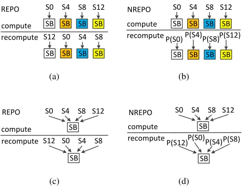
Fig. 4: A comparison between REPO and NREPO (a) REPO in 128-bit datapath (b) NREPO in 128-bit datapath (c) REPO in 8-bit datapath (d) NREPO in 8-bit datapath
are the bytes in the first row of the state.They are byte-wise permuted and recomputed on different S-boxes. In Fig. 4(b), NREPO bit-wise permutes each byte and recomputes the bytes on the same S-box. In Fig. 4(c), only one S-box is present in an 8-bit datapath AES. Although the byte order is permuted in recomputation, the bytes are computed by the same S-box. Therefore, REPO cannot detect faults that last during the computation and recomputation. Even if there is only one S-box, each byte is bit-wise permuted and recomputed on the same S-box in Fig. 4(d). NREPO has 0.025 FMR for those faults that last for both the computation and recomputation.
4.2 Can one use NREPO in 32-bit or 128-bit AES datapath?
NREPO has low FMR and area overhead in 8-bit AES implementation. The property NREPO uses still hold in 32-bit and 128-32-bit datapaths. We recommend REPO for 128-32-bit datapath since it detects all single byte faults [26]. We recommend the scheme in [7] for 32-bit datapath since its data in the computation and recomputation are done in different modules, which yields a lower FMR than NREPO.
4.3 Can one use NREPO in the AES decryption?
One can use NREPO in the AES decryption. Although AES decryption uses InvSubBytes and InvMixColumns, In-vSubBytes contains the inversion and affine transformation and InvMixColumns can be converted to normal basis multiplication.
4.4 Can one combine NREPO with other CED techniques to achieve stronger fault resilience?
NREPO is a technique that exploits the algorithmic property. As we have shown, one can combine it with DDR to boost the throughput. One can also implement parity along with NREPO to achieve even lower FMR but without modifying the parity scheme since the permutation does not change the parity of the byte. Most notably, one can also combine NREPO with REPO to reduce the FMR of REPO in the 128-bit datapath.
4.5 Can one use NREPO in other cryptographic algorithms?
NREPO uses the permutation property in normal basis multiplication and inversion. Theorem 1 and 2 show that any
GF(22m)has such property. Block ciphers such as Camellia [4] and Clefia [25], stream ciphers such as LEX [6], hash
5
Conclusion
NREPO uses the permutation property in normal basis arithmetic. We integrate NREPO into the AES circuit, and evaluated its performance using a 45nm ASIC library. The throughput of NREPO can be enhanced by DDR. The FMR is 25 to 50 times lower than parity and robust code. NREPO is a fine-grained CED primitives that one can use for normal basis multiplication and inversion. It is particularly suited for implementations in which the computation resources are scarce or it is difficult to use redundant resources.
6
Acknowledgments
This material is based upon work supported by the NSF CNS program under grant 0831349. Debdeep would like to thank Indo-USSTF fellowship to NYU School of Engineering, in 2012.
References
1. Predicative Technology Model. http://ptm.asu.edu/.
2. Michel Agoyan, Jean-Max Dutertre, David Naccache, Bruno Robisson, and Assia Tria. When clocks fail: On critical paths and clock faults.In Proc. CARDIS, pages 182–193, 2010.
3. SkSubidh Ali, Debdeep Mukhopadhyay, and Michael Tunstall. Differential fault analysis of AES: Towards reaching its limits.
J. Crypto. Engineering, pages 1–25, 2012.
4. Kazumaro Aoki, Tetsuya Ichikawa, Masayuki Kanda, Mitsuru Matsui, Shiho Moriai, Junko Nakajima, and Toshio Tokita. Camellia: A 128-bit block cipher suitable for multiple platforms - design and analysis.In Proc. Selected Areas in Cryptography, pages 39–56, 2001.
5. A. Barenghi, L. Breveglieri, I. Koren, and D. Naccache. Fault injection attacks on cryptographic devices: Theory, practice, and countermeasures.Proceedings of the IEEE, 100(11):3056–3076, 2012.
6. A. Biryukov. The design of a stream cipher lex.In Proc. Selected Areas in Cryptography, pages 67–75, 2007.
7. G. Canivet, P. Maistri, R. Leveugle, J. Clédière, F. Valette, and M. Renaudin. Glitch and laser fault attacks onto a secure aes implementation on a sram-based fpga.J. Cryptology, 24, 2011.
8. David Canright. A Very Compact Rijndael S-box.Technical Report NPS-MA-04-001, 2004.
9. A. Dehbaoui, J. Dutertre, B. Robisson, and A. Tria. Electromagnetic transient faults injection on a hardware and a software implementations of AES.In Proc. IEEE FDTC, pages 7–15, 2012.
10. P. Gauravaram, L. R. Knudsen, K. Matusiewicz, F. Mendel, C. Rechberger, M. Schläffer, and S. S. Thomsen. Grøstl-a sha-3 candidate. http://www.groestl.info/Groestl.pdf, 2011.
11. Tim Good and Mohammed Benaissa. AES on FPGA from the fastest to the smallest.In Proc. CHES, pages 427–440, 2005. 12. Xiaofei Guo and R. Karri. Invariance-based Concurrent Error Detection for Advanced Encryption Standard. In Proc. DAC,
pages 573–578, 2012.
13. Xiaofei Guo, Debdeep Mukhopadhyay, and Ramesh Karri. Provably secure concurrent error detection against differential fault analysis. Cryptology ePrint Archive, Report 2012/552, 2012.http://eprint.iacr.org/.
14. P. Hämäläinen, T. Alho, M. Hännikäinen, and T.D. Hämäläinen. Design and implementation of low-area and low-power AES encryption hardware core.In Proc. IEEE Euromicro Conf. on Digital System Design, pages 577–583, 2006.
15. D. Karaklaji´c, J.-M. Schmidt, and I. Verbauwhede. Hardware designer’s guide to fault attacks.IEEE Trans. VLSI, 21(12):2295– 2306, 2013.
16. Ramesh Karri, Kaijie Wu, P. Mishra, and Y. Kim. Concurrent error detection schemes of fault based side-channel cryptanalysis of symmetric block ciphers.IEEE Trans. CAD, 21(12):1509–1517, 2002.
17. Farouk Khelil, Mohamed Hamdi, Sylvain Guilley, Jean Luc Danger, and Nidhal Selmane. Fault analysis attack on an aes fpga implementation.In Proc. New Technologies, Mobility and Security, pages 1–5, 2008.
18. Konrad J. Kulikowski, Mark G. Karpovsky, and Er Taubin. Robust codes for fault attack resistant cryptographic hardware. In
Proc. IEEE FDTC, pages 1–12, 2005.
19. M. Mozaffari-Kermani and A. Reyhani-Masoleh. Concurrent structure-independent fault detection schemes for the Advanced Encryption Standard.IEEE Trans. Computers, 59(5):608–622, 2010.
20. P. Maistri and R. Leveugle. Double-data-rate computation as a countermeasure against fault analysis.IEEE Trans. Computers, 57(11):1528–1539, Nov 2008.
22. National Institute of Stardards and Technology (NIST). Advanced Encryption Standard (AES). http://csrc.nist.gov/publications/ fips/fips197/fips-197.pdf, Nov 2001.
23. Svetla Nikova, Vincent Rijmen, and Martin Schläffer. Using normal bases for compact hardware implementations of the AES s-box.In Proc. Security and Cryptography for Networks, pages 236–245, 2008.
24. Akashi Satoh, Takeshi Sugawara, Naofumi Homma, and Takafumi Aoki. High-performance concurrent error detection scheme for AES hardware.In Proc. CHES, pages 100–112, 2008.
25. Sony Corporation. The 128-bit blockcipher clefia: Algorithm specification. http://www.sony.net/Products/clefia, 2007. 26. X. Guo and R. Karri. Recomputing with permuted operands: A concurrent error detection approach. IEEE Trans. CAD,

![Fig. 2: Simulation results of burst faults show that the FMR of NREPO is superior to that of the parity [19, 21] androbust code [18]](https://thumb-us.123doks.com/thumbv2/123dok_us/7913210.1313901/5.612.76.589.277.395/simulation-results-burst-faults-nrepo-superior-parity-androbust.webp)
![Table 1: CED implementations on 45nm ASIC [1]. a. hardware redundancyb. MC and ARK are protected by theparity scheme in [21]c](https://thumb-us.123doks.com/thumbv2/123dok_us/7913210.1313901/7.612.210.401.120.331/table-implementations-asic-hardware-redundancyb-protected-theparity-scheme.webp)