Simulation Model of H6 Transformerless
Single Phase Full Bridge PV Grid tied
Inverters
Madhuri Kshirsagar1, Dr. P. J. Shah2
PG Student, Department of Electrical Engineering, SSBT's COET Jalgaon, India HoD, Department of Electrical Engineering, SSBT's COET Jalgaon, India
ABSTRACT: Photovoltaic (PV) generation systems are widely employed in transformer less inverters, in order to achieve the benefits of high efficiency and low cost. Safety requirements of leakage currents are met by proposing the various transformers less inverter topologies. The intrinsic relationship between H5, HERIC and H6 is revealed. The proposed H6 topology has been discussed as well. For a detailed analysis with operation modes and modulation strategy one of the proposed H6 inverter topologies is taken as an example. The leakage current in transformerless inverter is stated in detail. In this paper the H6 topology is proposed by using Inverted sine pulse width modulation (ISPWM). The results are compared with traditional sinusoidal pulse width modulation (SPWM). The proposed topology is simulated using MATLAB simulink software.
KEYWORDS: transformerless inverters, leakage currents, SPWM , ISPWM.
I.INTRODUCTION
Grid-connected photovoltaic (PV) systems, particularly low-power single-phase systems (up to 5 kW), are becoming more important worldwide. They are usually private systems where the owner tries to get the maximum system profitability. Issues such as reliability, high efficiency, small size and weight, and low price are of great importance to the conversion stage of the PV system [1]. Quite often, these grid-connected PV systems include a line transformer in the power-conversion stage, which guarantees galvanic isolation between the grid and the PV system, thus providing personal protection. Furthermore, it strongly reduces the leakage currents between the PV system and the ground, ensures that no continuous current is injected into the grid, and can be used to increase the inverter output voltage level. The line transformer makes possible the use of a full-bridge inverter with unipolar pulse width modulation (PWM). It requires only four insulated gate bipolar transistors (IGBTs) and has a good trade-off between efficiency, complexity and price. Due to its low frequency, the line transformer is large, heavy and expensive. Technological evolution has made possible the implementation, within the inverters, of both ground-fault detection systems and solutions to avoid injecting dc current into the grid. The transformer can then be eliminated without impacting system characteristics related to personal safety and grid integration. In addition, the use of a string of PV modules allows maximum power point (MPP) voltages large enough to avoid boosting voltages in the conversion stage. This conversion stage can then consist of a simple buck inverter, with no need of a transformer or boost dc–dc converter, and it is simpler and more efficient [2]. But if no boost dc–dc converter is used, the power fluctuation causes a voltage ripple in the PV side at double the line frequency. This in turn causes a small reduction in the average power generated by the PV arrays due to the variations around the MPP.
ISSN (Print) : 2320 – 3765 ISSN (Online): 2278 – 8875
I
nternational
J
ournal of
A
dvanced
R
esearch in
E
lectrical,
E
lectronics and
I
nstrumentation
E
ngineering
(An ISO 3297: 2007 Certified Organization)
Vol. 5, Issue 12, December 2016
dc–dc stage. The full-bridge topology requires half of the input voltage demanded by the half-bridge topology, that is, around 350 V for European applications. In order to avoid a varying common-mode voltage, the full bridge has to be modulated with bipolar PWM, a modulation strategy that leads the converter to a low efficiency and a high current ripple [5]. In this paper, an improved grid-connected inverter topology for transformerless PV systems is presented, which can sustain the same low input voltage as the full-bridge inverter and guarantee not to generate the common-mode leakage current.
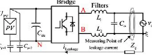
Fig. 1. Leakage current path for transformerless PV inverters.
The leakage currents lead to serious safety and radiated interference issues. Therefore, they must be limited within a reasonable range. As shown in Fig. 1, the leakage current iLeakage is flowing through the loop consisting of the parasitic capacitances (CPV1 and CPV2), bridge, filters (L1 and L2), utility grid, and ground impedance Zg. The leakage current path is equivalent to an LC resonant circuit in series with the CM voltage, and the CM voltage vcm is
defined as,
V = + (1) where vAN is the voltage difference between points A and N, vBN is the voltage difference between points B and N. L1
and L2 are the output filter inductors.
In order to eliminate leakage currents, the CM voltage must be kept constant or only varied at low frequency, such as 50 Hz/60 Hz. The conventional solution employs the half-bridge inverter. The filter inductor L2 is zero in the half bridge inverters. Therefore, (1) is simplified as
V = (2) Many solutions have been proposed to realize CM voltage constant in the full-bridge transformerless inverters [6], [7]. A traditional method is to apply the full-bridge inverter with the bipolar sinusoidal pulse width modulation (SPWM). The CM voltage of this inverter is kept constant during all operating modes. Thus, it features excellent leakage currents characteristic. However, the current ripples across the filter inductors and the switching losses are likely to be large. The full-bridge inverters with unipolar SPWM control are attractive due to the excellent differential-mode (DM) characteristics such as smaller inductor current ripple, and higher conversion efficiency. However, the CM voltage of conventional unipolar SPWM full bridge inverter varies at switching frequency, which leads to high leakage currents [8], [9]. Two solutions could be applied to solve this problem. One solution is to connect the PV negative terminal with the neutral line of the utility grid directly, such as the Karschny inverter derived from buck–boost converter, and the inverters derived from virtual dc-bus concept. The CM voltage is kept constant by these full-bridge topologies with unipolar modulation methods. Another solution is to disconnect the dc and ac sides of the full-bridge inverter in the freewheeling modes.
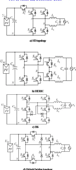
II.TRANSFORMERESS INVERTER TOPOLOGIES
a) H5 topology
b) HERIC
c) H6
d) Hybrid bridge topology
ISSN (Print) : 2320 – 3765 ISSN (Online): 2278 – 8875
I
nternational
J
ournal of
A
dvanced
R
esearch in
E
lectrical,
E
lectronics and
I
nstrumentation
E
ngineering
(An ISO 3297: 2007 Certified Organization)
Vol. 5, Issue 12, December 2016
Fig. 2(a) shows the H5 topology. It employs an extra switch on the dc side of inverter. As a result, the PV array is disconnected from the utility grid when the inverter output voltage is at zero voltage level, and the leakage current path is cut off. The HERIC topology shown in fig. 2(b) employs two extra switches on the ac side of inverter, so the leakage current path is cut off as well. However, its power device cost is higher than that of the H5 topology. Fig. 2(c) and (d) shows the H6-type topology and the hybrid-bridge topology respectively. Comparing with a full-bridge inverter, two extra switches are employed in the dc sides of these two topologies. Furthermore, both the H5 topology and the HERIC topology have been compared in terms of efficiency and leakage currents characteristic. However, these topologies have never been analyzed form the point of view of topological relationships. In this paper, a family of novel H6 full-bridge topologies is proposed for the transformerless PV grid-tied inverters.
An extra switch is inserted to the H5 topology for forming a new current path and for the purpose of reducing conduction loss [10] - [12]. Therefore, in the active modes, the inductor current of the proposed H6 topology flows through two switches during one of the half-line periods and through three switches during another half-line period. The proposed H6 topology has achieved the minimum conduction loss, and also has featured with low leakage currents. On the other hand, the topological relationship between H5 topology and HERIC topology is revealed, and the methods for generating HERIC topology from H6-type topology and from hybrid-bridge topology are presented, respectively. The operation modes of the H6 topology are discussed in detail further.
a)Active mode in the positive half period.
b) Freewheeling mode in the positive half period.
d) Freewheeling mode in the negative half period.
Fig.3 Equivalent circuits of operation modes of H6 Inverter.
Mode I is the freewheeling mode in the negative half period, voltage of the topology, VAB = VAN − VBN. The CM
voltage VCM = 0.5(VAN +VBN). Mode I is the active mode in the positive half period of the utility grid voltage, as shown
in Fig.4 (a). S1, S4, and S5 are turned ON, and the other switches are turned OFF. The inductor current is flowing through S1, S4, and S5. VAN = UPV, VBN = 0; thus, VAB = UPV, and the CM voltage VCM = (VAN + VBN)/2 = 0.5UPV.
Mode II is the freewheeling mode in the positive half period of the utility grid voltage, as shown in Fig.4 (b). S1 is turned ON; the other switches are turned OFF. The inductor current is flowing through S1 and the antiparalleled diode of S3. VAN = VBN≈ 0.5UPV; thus, vAB = 0, and the CM voltage VCM = (VAN + VBN )/2 ≈ 0.5UPV.
Mode III is the active mode in the negative half period of the utility grid voltage, as shown in Fig.4 (c). S2, S3, and S6 are turned ON; the other switches are turned OFF. The inductor current is flowing through S2 and S6. Although S3 is turned ON, there is no current flowing through it, and the switch S3 has no conduction loss in this mode. Nevertheless, in the H5 topology, the inductor current flows through S2, S3, and S5. Therefore, the conduction loss of proposed topology is less than that of H5 topology. In this mode, VAN = 0, VBN = UPV; thus, VAB = −UPV, and the CM voltage
VCM = (VAN + VBN)/2 = 0.5UPV.
Mode IV is the freewheeling mode in the negative half period of the utility grid voltage, as shown in Fig.4 (d). S3 is turned ON, and the other switches are turned OFF. The inductor current is flowing through S3 and the antiparalleled diode of S1. VAN = VBN≈ 0.5UPV; thus, VAB = 0, and the CM voltage VCM = (VAN + VBN)/2 ≈ 0.5UPV. Based on the
aforementioned analysis, the PV array can be disconnected from the utility grid when the output voltage of the proposed H6 inverter is at zero voltage level and the leakage current path is cut off. The CM voltage of the proposed topology in each operation mode is equals to 0.5UPV, and it results in low leakage current characteristic of the proposed
H6 topologies [13].
III. ISPWM TECHNIQUE
The harmonics in the inverter can be eliminated using pulse width modulation (PWM) switching technique. In the conventional inverters the sinusoidal PWM is used in which sine wave is the modulating wave and triangular wave is the carrier wave. But it inhibits poor performance with regard to maximum attainable voltage and power.
ISSN (Print) : 2320 – 3765 ISSN (Online): 2278 – 8875
I
nternational
J
ournal of
A
dvanced
R
esearch in
E
lectrical,
E
lectronics and
I
nstrumentation
E
ngineering
(An ISO 3297: 2007 Certified Organization)
Vol. 5, Issue 12, December 2016
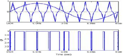
Thus the modulation strategy employed in the inverter is the ISPWM. In this technique, inverse sine wave is used as carrier wave. The ISPWM technique has better spectral quality and higher fundamental component compared conventional sinusoidal PWM. Also there is reduction in total harmonic distortion (THD) [14]. The pulses are generated when amplitude of the reference sine wave is greater than that of inverted sine carrier .The total harmonic distortion for different values of switching frequencies is obtained and is found to be lesser than the conventional methods. By employing the ISPWM, it has been proved that the fundamental voltage is improved throughout the working range and is greater than the voltage obtained using conventional methods.
IV. SIMULATION AND RESULTS
The simulation of H6 inverter is carried out with ISPWM technique, which is as shown in figure below. The figure consist of the H6 inverter along with the ISPWM generation scheme and the output are shown with the help of scopes separately.
Fig. 5. Simulation of H6 inverter with ISPWM Technique
The harmonics in the output voltage of converters can be reduced using Pulse-Width Modulation (PWM) switching techniques. PWM methods reduce the harmonics by shifting frequency spectrum to the vicinity of high frequency band of carrier signal. In the case of sinusoidal PWM (SPWM) scheme, the control signal is generated by comparing a sinusoidal reference signal and a triangular carrier.
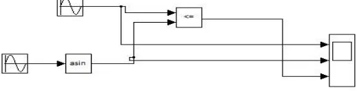
Fig. 6: Simulink Model for ISPWM technique
Fig. 7: Grid voltage using ISPWM technique.
The above figures show that the output obtained is purely sinusoidal. The voltage amplitude is 230 V.
Fig. 8: Grid current using ISPWM technique.
The amplitude of the current is nearly 10 A and also the waveform is sinusoidal. The results of the ISPWM technique when compared with the conventional SPWM, we can see that the ripples in the output are reduced to a great amount in the transformerless inverter.
Fig. 10: Leakage current using ISPWM
Leakage current is the current that flows through the protective ground conductor to ground. In the absence of a grounding connection, it is the current that could flow from any conductive part or the surface of non-conductive parts to ground if a conductive path was available (such as a human body). There are always extraneous currents flowing in the safety ground conductor. In the transformerless inverter the leakage current flows between the PV system and the ground. It could pose a shock hazard to someone touching the ungrounded equipment and ground at the same time.
ISSN (Print) : 2320 – 3765 ISSN (Online): 2278 – 8875
I
nternational
J
ournal of
A
dvanced
R
esearch in
E
lectrical,
E
lectronics and
I
nstrumentation
E
ngineering
(An ISO 3297: 2007 Certified Organization)
Vol. 5, Issue 12, December 2016
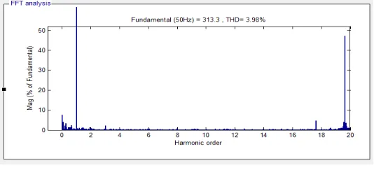
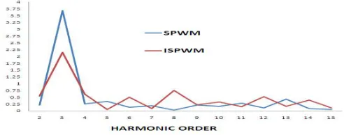
The comparison of both the techniques can also explained with the help of graph as shown in figure below. It can be seen that total %THD of ISPWM is 3.98% and that of SPWM is 6.21% respectively. Thus with the help of ISPWM technique the obtained THD is less than the conventional SPWM technique.
Fig 12. Graphical comparison between PWM techniques.
VI. CONCLUSION
The novel grid connected H6 inverter is presented in the paper. The inverter is implemented using novel ISPWM technique. The results of the voltage, current and the leakage currents are compared with SPWM. It is seen that the quality of output is greater in ISPWM than the SPWM. Also the THD of this novel technique is less than the other and also the graphical comparison of both the techniques is explained. Hence the H6 inverter with ISPWM technique can be the better solution for single phase grid connected systems.
REFERENCES
1. F. Blaabjerg, Z. Chen, And S. B. Kjaer “Power Electronics As Efficient Interface In Dispersed Power Generation Systems,” IEEE Trans. on
Power Electronics, Vol. 19, no. 5, pp. 1184–1194, Sep. 2004.
2. Soeren Baekhoej Kjaer, John K. Pedersen and Frede Blaabjerg,"A review of Single phase grid connected Inverters for photovoltaic Modules",
IEEE Trans. on Industry Application, Vol. 41, No. 5, Sept/Oct. 2005, pp. 1292-1306.
3. Oscar Lopez, Francisco D. Freijedo, Alejandro G. Yepes, Pablo Fernandez- Comesana, Jano Malvar, Remus Teodorescu, and Jesus
Doval-Gandoy, "Eliminating Ground Current in a Transformerless Photovoltaic Application" IEEE Transaction on Energy Conversion, vol.25, no.1, March 2010.
4. N. Mohan, T. M. Undeland, and W. P. Robbins, Power Electronics -Converters, Applications and Design, 3rd Ed. New York: Wiley, 2003.
5. Z. Chen and E. Spooner, “Voltage source inverters for high-power, variable-voltage dc power sources,” Proc. Inst. Elect. Eng., vol. 148, no. 5,
pp. 439–447, Sept. 2001.
6. J. P. Benner and L. Kazmerski, “Photovoltaics gaining greater visibility,” IEEE Spectrum, pp. 34–42, Sept. 1999.
7. Madhuri Kshirsagar , Dr. P. J. Shah " A Review of the single Phase Transformer Less Full Bridge PV Grid Inverters" International Journal for
Scientific Research & Development(IJSRD), Vol. 4, no. 02, 2016.
8. Madhuri Kshirsagar, Dr. P. J. Shah "Evaluation of Transformerless Inverters for Single Phase Photovoltaic Systems "International Journal of
Innovative Research in Electrical, Electronics, Instrumentation and Control Engineering (IJIREEICE) ,Vol. 4, no. 6, June 2016.
9. Madhuri Kshirsagar, Dr. P. J. Shah "High Efficiency H6 Transformerless topology based Single Phase Full Bridge PV Grid tied Inverters"
Asian Journal of Science and Technology, Vol.7 issue 11, Nov. 2016, pp.3837- 3841.
10. E.Twining and D. G. Holmes, “Grid current regulation of a three-phase voltage source inverter with an LCL input filter,” IEEE Trans. Power
Electron., vol. 18, no. 5, pp. 888–895, May 2003.
11. S. B. Kjaer, J. K. Pederson, And F. Blaabjerg, “A Review Of Single-phase Grid-connected Inverters for Photovoltaic Modules,” IEEE
Transaction on Ind. Appl., Vol. 41, No. 5, pp. 1292–1306, Sep/Oct. 2005.
12. R.Gonzalez, J. Lopez, P. Sanchis and L. Marroyo, “Transformerless Inverter for Single-phase Photovoltaic Systems,” IEEE Transaction on
Power Electronics. , Vol. 22, No. 2, pp. 693–697, Mar. 2007.
13. Li Zhang, Kai Sun, Yan Xing and Mu Xing “H6 Transformerless Full-Bridge PV Grid-Tied Inverters” IEEE Transactions on Power
Electronics, Vol. 29, no.3, pp. -1229 -1238, March 201
14. R .Antony Raja Sekar and D. Arun Prasad "Improved Transformerless inverter for PV grid Connected Power System by using ISPWM