Available online: https://edupediapublications.org/journals/index.php/IJR/ P a g e | 229
Microcontroller Based Fan Speed Control System
1Abdul Aziz, 2Mohd Saber Hussain, 3Mohd Sarwar Moinuddin, 4Ali Alfahad Raza, 5M A Haleem Aktar1234B.Tech Student, 5Asst.Professor
12345Department Of Electrical & Electronics Engineering,
Lords Institute Of Engineering And Technology Hyderabad, Telangana, India .
ABSTRACT:- Design and implementation of Microcontroller based automatic Fan speed regulator using temperature sensor is represented here. Most of the available Fans today are controlled manually by voltage regulators which have different stages of speed. During summer nights, especially the room temperature is initially quite high, as time passes, the temperature starts dropping. Also, after a person falls asleep, the metabolic rate of one’s body decreases, and one is expected to wake up from time to time to adjust the speed of the Fan. Many people who are disabled / physically challenged persons are affected the most because of the inconveniences associated in changing the Fan speed level manually when the room temperature changes. So, an efficient automatic Fan speed control system that automatically changes the speed level according to the change in environment / room temperature which is more comfortable than manual system. This project has been designed in such a way that the required components are available in local market. Therefore an indigenous low cost
control scheme has been developed which can be used in real life application.
Keywords:- Temperature Control Fan; Speed Regulator; Microcontroller.
I.
INTRODUCTION
Available online: https://edupediapublications.org/journals/index.php/IJR/ P a g e | 230
manually [2]. Thus electricity usage by Fan about 100watts~80watts (depending on the make) is more than what is required for the desired low speed operation of Fan (approximately 10 watts to 30watts). So, an efficient and reliable system that automatically changes the Fan speed level according to the change in room temperature was built to solve the problems and shortcomings associated with manually method of Fan speed control [3].
Before fan is invented, bird feather had been used. As year goes by, human being very creative by the creative technology which make human’s life easier. Nowadays, fan and air conditioner has been a must appliance to each home, offices and the industries. Mostly each invention will be the modified from years for a change. The same thing goes to fan. Basically, fan has been run manually. To change the speed one has to push the speed button at the control panel of the fan. There are so many machines or electrical appliances that can function automatically. With the invention of the fan automated system using temperature sensor, one does not have to change fan speed manually. It can change fan speed to lower or higher speed according to the temperature. Nowadays, the usage of fan is controlled manually by pressing on the switch button. This non-innovative feature makes it unable to turn on automatically according to temperature changes. So, an automatic temperature control system
technology is applied for the switching purpose in this circuit.
Due to its advantages, many researches focusing on automatic temperature control system application in different fields will gain the benefits. For examples, Room Temperature based Fan Speed Control System using Pulse Width Modulation Technique [4], Design an Automatic Temperature Control System for Smart Electric Fan Using PIC [5],an automatic temperature controller for multi element array hyperthermia systems [6],multi loop automatic temperature control system design for fluid dynamics [7],design of automatic temperature- control circuit module in tunnel microwave heating system [8], an automatic temperature controller for multi-element array hyperthermia systems [9], multi-loop automatic temperature control system design for fluid dynamics [10], automatic temperature control for transport airplanes [11], design of automatic temperature control system on laser diode of erbium-doped fiber source [12], design of automatic temperature-control circuit module in tunnel microwave heating system [13].
Available online: https://edupediapublications.org/journals/index.php/IJR/ P a g e | 231
effective and also we can save more electricity. The circuit provides a comfort for human’s life, especially for senior and physically handicapped citizens. It really helps to solve the problem of handicapped person when to switch on the fan.
II.
BLOCK PRESENTATION OF
PROJECT
Fig.1: Block diagram representation of the project.
The above diagram is the basic block diagram of the whole project. The temperature sensor is employed to sense the temperature from atmosphere. It produces voltage if rises temperature. The output of the Temperature sensor (analogue signal) is fed to the input of the ADC, which converts the analogue temperature value to digital equivalent required by the micro-controller. Thus, the output of the ADC is directly coupled to the microcontroller whose main task is to control / regulate the Fan speed via the actuators. The LCD made available in the system is used to display all the information of
the system like: - the Fan speed and the room temperature (at any point in time).
Flow Chart
Available online: https://edupediapublications.org/journals/index.php/IJR/ P a g e | 232
Fig.2: Flow Chart of the Project
• If read temperature is greater than set temperature, going next step.
• If read temperature is smaller than set temperature, than again read temperature.
• If temperature is greater than previous temperature, increase seed and display.
• If temperature is small than previous temperature, decrease seed and display.
III.
FAN SPEED CONTROL
SYSTEM CIRCUIT DESIGN
This section describes how the speed of fan is
controlled by PWM output from
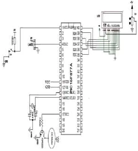
microcontroller, with the change in room temperature. The schematic circuit diagram of fan speed control system shown in Fig. 8.
Fig. 8 Schematic circuit diagram of fan speed control system
Available online: https://edupediapublications.org/journals/index.php/IJR/ P a g e | 233
to the room temperature change. For processing analog signals, microcontroller has analog to digital converter which converts analog signals to digital ones. The LM35 gives 10mv for each 1°c change in the temperature; this value is analog value and should be converted to digital. Any change in the temperature will be send to the microcontroller via PORTA pin 2, which have been specified by us in the program using TRISA. The microcontroller used in this system has inbuilt PWM module which is used to control speed of the fan by varying the duty cycle. According to the readings from the temperature sensor, duty cycle is varied automatically thus controlling fan speed. The microcontroller will send the PWM signal via pin RC2 in port C to the transistor which working as switch to the fan. Crystal oscillator is connected in between pin 13 (osc1) and pin 14 (osc2) of PIC16F877A, those are pins if we want to provide external clock to the microcontroller. 0.1 μF bypass capacitor used on the output pin +5 V of the voltage regulator to smooth out the supply voltage to microcontroller and LCD. Vout pin of temperature sensor LM35 is connected on pin RA2 which is ADC0 of all ADC input pins. Pin 3 of LCD is connected to ground via 1Kohm resistor to set the contrast of the LCD to display temperature on LCD. Pins from RB2 to RB7 are connected to remaining LCD pins used for data and control signals between LCD and microcontroller PWM
output
is given to gate terminal of Transistor NPN
KSP2222A from microcontroller. Transistor
NPN KSP2222A is high switching speed
power switch. This switches on and off at
PWM frequency and controls the voltage
across motor. When KSP2222A is on, the
motor starts to gain speed and off then motor
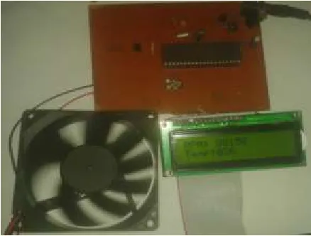
looses speed. The hardware circuits that
have been designed for the controlled fan
speed system in this research, which consists
of the LM35, PIC microcontroller, BLDC
motor and LCD as shown in Fig. 9, which
also include the crystal circuit.
Fig. 9 Hardware circuit of fan speed control system
IV.
RESULT AND DISCUSSION
Available online: https://edupediapublications.org/journals/index.php/IJR/ P a g e | 234
method was to use the voltmeter to measure the output of the LM35DZ temperature sensor. Since the output of this sensor is 10mv for each 1°C. Also another method to calibrate this work, was an external temperature sensor (thermometer) to gauge the room temperature. Fig. 10 describes the calibration process using the voltmeter and the thermometer.
Fig. 10 Calibration process using the voltmeter and the thermometer
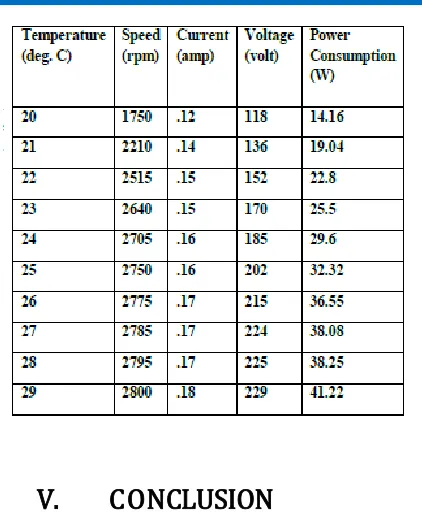
The calibration process was done in different day times which can be summarized in Table I.
TABLE I
CALIBRATION PROCESS
V.
CONCLUSION
Available online: https://edupediapublications.org/journals/index.php/IJR/ P a g e | 235
Future Scope: In the future, there are several improvements can be made in order to upgrade the features such as
1. It can be extended for three phase induction load.
2. It can be extended by interfacing with android mobile to show temperature and RPM of fan in mobile.
REFERENCES
[1] [Environment Monitoring. 2008 International Workshop on Education Technology and Training & 2008 International Workshop on Geoscience and Remote Sensing, 496-499.
[2] Bai, Y., & Ku, Y. (2008).Automatic Room Light Intensity Detection and Control Using a Microprocessor and Light Sensors. IEEE Transactions on Consumer Electronic, 1173.
[3] National Semiconductor (2000, November) Precision Centigrade Temperature Sensors. Retrieved October 25, 2009, from National Semiconductor.
[4] Vaibhav Bhatia, Gavish Bhatia,” Room Temperature based Fan Speed Control Sys tem using Pulse Width Modulation Technique,” International Journal of Computer Applications (0975 – 8887), Volume 81 – No5, November 2013
[5] Zairi Ismael Rizman, Kim Ho Yeap, Nuraiza Ismail,” Design an Automatic Temperature Control System for Smart Electric Fan Using PIC,” International Journal of Science and Research (IJSR), India Online ISSN: 2319-7064
[6] B. LEVĂRDĂ and C. BUDACIU, “The Design Of Temperature Control System Using Pic18f46201 ,” ICSTC, PP 282−286, 2010.
[7] J.E. Johnson, P.F. Maccarini, D. Neuman, P.R. Stauffer, “Automatic Temperature Controller for Multi element Array Hyperthermia Systems,” IEEE Transactions on Biomedical Engineering, pp. 1006-1015, 2006.
[8] G.J. Fiedler, J. Landy, “Multi-loop Automatic Temperature Control System Design for Fluid Dynamics Facility Having Several Long Transport Delays,” IEEE IRE Transactions on Automatic Control, pp. 81 -96, 1959. [9] T, Fu, X. Wang, G. Yang, “Design of Automatic- Temperature-Control Circuit Module in Tunnel Microwave Heating System,” In Proceedings of the IEEE International Conference on Computational and Information Sciences, pp. 1216-1219, 2010.
[10] Z.H.-Quan and L. Qian`, “The Automatic Temperature System With Fuzzy Self-Adaptive PID Control in Semiconductor Laser,” In Proceedings of the IEEE Intern [11] J.E. Johnson, P.F. Maccarini, D. Neuman, P.R. Stauffer, “Automatic Temperature Controller for Multielement Array Hyperthermia Systems,” IEEE Transactions on Biomedical Engineering, 53 (6), pp. 1006-1015, 2006.
[12] G.J. Fiedler, J. Landy, “Multi-loop Automatic Temperature Control System Design for Fluid Dynamics Facility Having Several Long Transport Delays,” IEEE IRE Transactions on Automatic Control, 4 (3), pp. 81-96, 1959. [13] R.E. Hedges, “Automatic Temperature Control for Transport Airplanes,” IEEE Transactions of the American Institute of Electrical Engineers, 66 (1), pp. 1197-1202, 1947.