To Analyze the Effect of Varying Fin Shapes
for Microprocessor Cooling
Pankaj V. Baviskar 1, Kapil A. Saner2, Nilesh P. Salunke3 , Vijay B. Jadhav4
Assistant Professor, Department of Mechanical Engineering, R.C.Patel Institute of Technology, Shirpur India1
Assistant Professor, Department of Mechanical Engineering, R.C.Patel Institute of Technology, Shirpur India2
Associate Professor, Head Department of Mechanical Engineering, R.C.Patel Institute of Technology, Shirpur India3
Assistant Professor, Department of Mechanical Engineering, R.C.Patel Institute of Technology, Shirpur India4
ABSTRACT: Microprocessor has become the heart of home/office PC systems. The microprocessor device require electrical energy for their work, the electrical energy is converted into heat energy this may affect the performance of a microprocessor. Heat sink was used to control the temperature of microprocessor in permissible limit. There are various parameters like heat sink material, fin thickness, number of fins, spacing between two fins, base plate thickness and fin shape etc. which affects the performance of heat sink. Material is one of the parameter that increase heat transfer rate. If copper is used in place of aluminium then heat transfer rate increases but at the same time cost also increases. The heat sink base plate thickness is parameter for improvement. When the base plate thickness was increased, the heat sink performed better. However, there are space limitations for every heat sink in a computer. Also the increase in number of fin was not a solution for improving heat transfer. So the fin shape is the parameter which can be studied in this work for better results. The work consists of numerical study of different fin profile heat sinks which are rectangular, circular, trapezoidal and triangular using ANSYS. The numerical results were validated with experimental test setup for rectangular fin shape heat sink. Validated numerical result signifies that the more heat transfer rate for triangular fin. So the modified triangular fin heat sink was fabricated and can be checked experimentally to get better results. The modified triangular heat sink shows that there was increase in heat transfer rate by 9% as compare to rectangular fin heat sink.
KEYWORDS: Microprocessor. Heat Sink. permissible limit.
I. INTRODUCTION
In microprocessors, power is mostly dissipated as heat energy. This conversion to heat energy is a function of the size of the wires and transistors, and the operating frequency of the processor. As transistors get smaller, the depletion region gets smaller and current leaks through the transistor even when it is off. This leakage produces additional heat, and wastes additional power. Heat can also cause materials to expand, which can alter the electrical characteristics of the tiny transistors and wires.
.
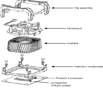
Fig. 1 Assembly of microprocessor and heat sink.
A heat sink is an environment or object that absorbs and dissipates heat from another object using thermal contact (either direct or radiant). Heat sinks are used in a wide range of applications wherever efficient heat dissipation is required; major examples include refrigeration, heat engines, cooling electronic devices and lasers.
The performance criterion of heat sinks is the thermal resistance, which is expressed as the temperature difference between the electronic components and ambient per watts of heat load. It is expressed with units K/W. Today’s electronic chips dissipate approximately 100 W maximum whereas this number will be multiples in the near future. The temperature differences from the heat sink surface to the ambient range from 100C to 350C according to the heat removal capability of the installed heat sink. Heat sinks may be categorized into five main groups according to the Cooling mechanism employed [18].
Passive heat sinks which are used generally in natural convection systems.
Semi-active heat sinks which leverage off existing fans in the system.
Active heat sinks employing designated fans for forced convection system.
Liquid cooled cold plates employing tubes in block design or milled passages in brazed assemblies for the use of pumped water, oil or other liquids, and
Phase change recirculating systems including two-phase systems that employ a set of boiler and condenser in a passive, self driven mechanism.
In this study, the shapes of fins for heat sink are investigated for efficient cooling of microprocessor.
II.LITERATURESURVEY
The literature regarding microprocessor cooling using heat sink was reviewed in this chapter.
Irfan Vohra et.al [1], analysed the Study of thermal Performance of circular pin fin and get the value of heat transfer coefficient, surface Nusselt number, thermal resistance and pressure drop for the heat sink of the different circular pin with trapezoidal fin profile at different velocity and constant heat input 10w and predict temperature distribution along the cylindrical pin with Trapezoidal fin. The results show that the Circular Pin of 3.75 mm diameter with trapezoidal Fin of 0.8 mm tip thickness heat Sink at 12.5m/s wind velocity has better unnaturally performance pressure because of max Nusselt number 1066.93 and heat transfer coefficient 51.60 W/M2K and thermal resistance 0.47 than the plate fin heat sink and other cases.
transfer in electronic components. For the purpose of study heat sink is modeled by using the optimal geometric parameter such as fin height, fin thickness, base height, fin pitch as 48 mm, 1.6 mm, 8mm, 2mm and after that simulation is done at different heat load of 50W, 75W, 100W and with a air flow at 15CFM and air inlet temperature is taken as 295 K. The simulation is carried out with a commercial package provided by fluent incorporation. 6 The result obtained taking into consideration only the thermal performance. And his result shows that For all the three profile compared for the maximum temperature attained on the basis of result governed by the CFD analysis, with the fin pitch 2mm the Trapezoidal heat sink shows that the maximum temperature attained is minimum as compared to the Rectangular and Parabolic heat sink and the parabolic heat sink shows the highest maximum temperature attained which is not desirable. Heat transfer coefficient and surface Nusselt number is Maximum in Trapezoidal heat sink for all the fin pitch and for different heat loads of 50W, 75W, 100W. As per the criterion for the selection of heat sink, the heat sink should have lowest thermal resistance and maximum heat transfer coefficient. The Trapezoidal Heat sink shows the lowest thermal resistance and the maximum heat transfer coefficient.
Ambeprasad.S.Kushwaha et.al [3], experimental analysis was made for the heat transfer for a heat sink having two profiles. One is without cut and another is with cut at the middle and it was observed that the temperature variation was more for a heat sink with cut as compare to heat sink without cut leading to higher heat transfer.
K. Pavan Kumar et.al [4], analysed the array of tree fins with slots has a better heat transfer capability when compared to a tree fin without slots. Copper alloy is best among the analysed materials, but owing to the cost, weight, availability and other factors aluminium alloy is recommended. The deformations of the various materials compared, have shown that slotted tree fins are in acceptable range to the given heat inputs (a maximum of 950C being the upper limit for a processor). Aluminium alloy can be used in the shape of tree fins with slots as a heat sink for an effective transfer of heat being generated and will not deform much at the given temperatures.
R. Sam Sukumar et.al [5], showed the CFD analysis of heat sinks which contain continuous rectangular fins, interrupted rectangular fins and interrupted rectangular through holes fins for electronic cooling is investigated. Based on the result obtained it can conclude that in the sense of junction temperature interrupted fins are efficient 7 than continuous. It also found that through holes for the interrupted fins has better performance than interrupted rectangular fins of heat sinks and reduction in weight due to more material removal from the standard.
Avram Bar-Cohen et.al [6], concluded that the temp of microprocessor is not same at every cross section it varies point to point. He also concludes that the temp range of hot spot is 50C to 300C & the temp increases with respect to hot spot size. The temp of microprocessor is maintained by using thermo electric coolers (TECS) & different thermal interface materials (TIMS). The rapid emergence of nano electronics, with the consequent rise in transistor density and switching speed, has led to a steep increase in microprocessor chip heat flux and growing concern over the emergence of on-chip hot spots. Attention is devoted to thermoelectric micro coolers and two-phase micro gap coolers. The advantages and disadvantages of these on chip cooling solutions for high heat flux hot spots are evaluated and compared.
Golnoosh Mostafavi et.al [7], analyzed the Steady-state external natural convection heat transfer from vertically-mounted rectangular interrupted fins numerically and experimentally. To perform an experimental study, a custom-designed test bed was developed to verify the analytical and numerical results. FLUENT software was used in order to develop a 2-D numerical model for investigation of interruption effects and performing parametric study. After regenerating, and validating the existing analytical results for fin spacing, a systematic numerical and experimental study was conducted on effect of fin interruption. Results show that adding interruptions to vertical rectangular fins enhances the thermal performance of fins. In a parametric study optimum interruption length for maximum fin performance was found and correlated.
material, Fin thickness, Number Of fins etc. will affect the heat transfer of heat sink. Some important conclusions can be drawn from this study, regarding the purpose of the presented work. Concluding remarks
• The microprocessor is important part in CPU and to control the temperature of microprocessor is important for efficient working.
• The temperature difference will vary depending on the type of architecture, clock speed, bus speed, and cache size of microprocessor.
• As the time increases the temp of the microprocessor increases at full & idle load conditions. • The temperature of microprocessor is not same at every cross section it varies point to point.
• As per the criterion for the selection of heat sink, the heat sink should have lowest thermal resistance and maximum heat transfer coefficient.
• For heat sink if copper material was used rather than aluminum the thermal resistance of the heat sink decreases. However, this makes the heat sink more expensive and heavier.
• The performance of heat sink is depends on various parameters like number of fins, fin thickness, fin shape, base plate thickness, fin material etc.
III.METHODOLOGY
In this work we are going to check numerical results for different fin shapes heat sink. For this purpose we were using ANSYS software to analyze particular Shapes of fins. This study also includes experimental observation for validating numerical results. Further study gives the fabrication of optimize fin to get optimum results.
A. Numerical Methodology:
Numerical analysis had been done with the help of Ansys software. For getting numerical results there is requirement of cad model. CATIA is the cad software in which we can design and create model. Ansys is the analysis software in which different models are used to solve the model.
B. CATIA modelling:
The software provides advanced technologies for mechanical design. CATIA has an innovative and instinctive user interface that unleashes the designer’s creativity. With the help of this software different heat sink models have been developed. The figure 2 shows the heat sink model with specified dimensions.
Fig. 2 Rectangular fin heat sink
C. Ansys Process:
Fig. 3 Flowchart of Numerical Procedure
After 3-D modelling of heat sink in catia v5, iges file will be exported, and then Ansys reads that iges file and meshing will be carried out on it. For present work aluminium alloy was selected as a material and with different meshing cell size mesh will be generated which can give the grid independent results for heat flux.
IV.EXPERIMENTALMETHODOLOGY
The objective of the experimental study is to investigate the base temperature of heat sink and temperature profile for the heat sink. In the literature survey it is observed that the maximum temperature range for microprocessor is 800C to 1000C depending on the capacity of microprocessor. If the temperature of microprocessor is not in the functional limit then it may stop the system. Thus, for verification it will take the temperature readings of heat sink in CPU at full load & idle load conditions as Shown in figure 4.
Sr. No.
Time In SEC
Temp at Full Load
Temp at Idle Load
1 10 45 40
2 20 50 45
3 30 55 55
4 40 60 58
5 50 75 65
6 60 80 70
TABLE I THE TEMPERATURE READINGS OF HEAT SINK IN CPU AT DIFFERENT TIME INTERVAL FOR FULL LOAD & IDLE LOAD CONDITIONS
Fig. 5 Graph temp v/s time at full load and idle load
From table1 and figure 5 it is observed that as the time increases the temperature increases at full load & idle load condition. It is also observed that at the range of 700C to 800 C the CPU will automatically stop the working.
V. EXPERIMENTAL SETUP
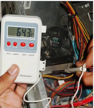
Now to validate these temperature readings the experimental setup was made as shown in figure 6.
Fig. 6 Experimental Setup.
from 230v to 12v which is required for heater. As heater will start, the stainless steel base plate start to heat at required temperature. In this setup the base plate is assume to be a microprocessor or heat input source for heat sink. As the temperature of base plate increases the heat sink which is pasted on the base plate is conduct the heat and it will get heated. Now take the temperature readings by using multi thermometer at various points on the heat sink and calculate the various parameters like heat transfer from heat sink, heat flux for sink, temperature profile for heat sink, heat transfer coefficient etc.
Fabrication and testing of modified heat sink:
With so many complex requirements and heat sink design options, this can be a challenging task. The various factors that impact heat sink specs & design are system airflow, orientation, attachment methods, size, ambient conditions, budget, etc. As designers and manufacturers of hundreds of heat sink solutions, Supply Concepts excels in solving thermal design challenges. As the triangular fin array has the smallest value of the optimum fin length and the maximum effective heat transfer surface area [9] also numerical results shows the better results for the triangular fin shape heat sink. So in this present work triangular fin shape type heat sink will be fabricated. On the basis of manufacturing process the different types of heat sink are as follows Extruded heat sink, Stamped heat sink, bonded fin heat sink, Folded fin heat sink, Forged Heat Sink, Swaged Heat Sink, Single Fin Assembly Heat Sink, Skived Heat Sinks [13].
In this present work the modified heat sink as shown in figure 7 is manufacture by wire cut EDM machining process which is tested on experimental setup and results were obtained.
Fig. 7 Modified heat sink
Results and Discussion:
Numerical analysis can gives the contours of various parameters such as temperature, heat flux etc. these can gives the clear idea for the heat transfer in heat sink. The below figure 8 to 11 shows the contours of temperature distribution and heat flux for various fin profiles for heat sink ( Rectangular, Circular, Trapezoidal and Triangular).
Fig. 10 Contour of temperature for trapezoidal heat sink. Fig. 11 Contour of temperature for triangular heat sink.
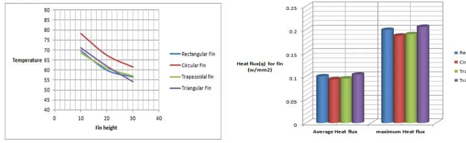
From the numerical results graphs were plotted for various fin profile of heat sink such as Temp V/s fin height and for maximum and average heat flux as shown in figure 12 and 13. It shows that temperature at the tip of triangular fin is less as compare to the other profiles of heat sink and the average heat flux and maximum heat flux for the triangular fin is maximum as compare to the other profiles of heat sink. So it signifies that the heat transfer rate for triangular heat sink profile is better than the other profiles of heat sink.
Fig. 12 Temperature distribution over the fin height. Fig. 13 Maximum and average heat flux for different heat sink.
VI.CONCLUSION
The experimental and numerical results shows that, The temperature at the tip of triangular fin heat sink is less as compared to rectangular fin heat sink and heat flux in the triangular fin heat sink is more as compared to rectangular fin heat sink which signifies maximum heat transfer rate. There was 9% increase in the heat transfer rate for triangular fin heat sink in the comparison of rectangular fin heat sink.
REFERENCES
[1] Irfan Vohra, Mohammad Azim Aijaz, Dr. B. B. Saxena “CFD Analysis of Cylindrical Pin with Trapezoidal Fin Heat Sink using ANSYS Fluent 14.0” International Journal of Emerging Technology and Advanced Engineering Volume 4, Issue5, May 2014.
[2] Ambeprasad.S.Kushwaha, Prof. Ravindra Kirar “Comparative Study of Rectangular, Trapezoidal and Parabolic Shaped Finned Heat sink” IOSR Journal of Mechanical and Civil Engineering (IOSR-JMCE) e-ISSN: 2278-1684 Volume 5, Issue6 Mar 2013.
[3] Mukesh Kumar, Anil Kumar, Sandeep Kumar “optimum design and selection of heat sink” International Journal of Application or Innovation in Engineering & Management (IJAIEM) Volume 2, Issue 3, March 2013.
[4] K. Pavan Kumar, P.V.Vinay, R.Siddhardha “Thermal and Structural Analysis of Tree Shaped Fin Array” Int. Journal of Engineering Research and Applications ISSN: 2248-9622, Vol. 3, Issue 6, Nov-Dec 2013.
[5] R. Sam Sukumar, G.Sriharsha, S.Bala Arun, P.Dilip kumar, Ch.Sanyasi Naidu “Modelling and analysis of heat sink with rectangular fins having through holes”Journal of Engineering Research and Applications (IJERA) ISSN: 2248-9622 Vol. 3, Issue 2, March -April 2013. [6] Avram Bar-Cohen, Peng Wang “Thermal Management of On-Chip Hot Spot” Journal of Heat Transfer MAY 2012, Vol. 134 /
051017-1Copyright2012 by ASME.
[7] Golnoosh Mostafavi, Mehran Ahmadi, Majid Bahrami “effects of geometrical parameters on natural convective heat transfer from vertically-mounted rectangular interrupted fins” Proceedings of the ASME 2012 Summer Heat Transfer Conference.
[8] Shivdas S. Kharche, Hemant S. Farkade “Heat transfer analysis through fin array by using natural convection” International Journal of Emerging Technology and Advanced Engineering ISSN 2250-2459, Volume 2, Issue 4, April 2012.
[9] Mehdi Nafar , Mohammad Tavassoli “An Analysis for Optimization of Heat Transfer for Various Heat Sink Cross-section and Length” Australian Journal of Basic and Applied Sciences, 5(12): 1685-1682, 2011 ISSN 1991-8178.
[10] R.Mohan, Dr.P.Govindarajan, “Thermal Analysis Of CPU With Composite Pin Fin Heat Sinks”, International Journal of Engineering Science and Technology Vol. 2(9), 2010.
[11]Saket Karajgikar, Dereje Agonafer, Kanad Ghose “Multi-Objective Optimization to Improve Both Thermal and Device Performance of a Non uniformly Powered Micro-Architecture” Journal of Electronic Packaging JUNE 2010.
[12] N.Nagarani “Experimental heat transfer analysis on annular circular and elliptical fins” International Journal of Engineering Science and Technology Vol. 2(7), 2010.
[13] B.Sri Aravindh, B.Sri Aravindh “Heat Sink Performance Analysis through Numerical Technique”, IEEE Symposium (NSSP08), Bangalore, 2008.
[14] A.-R. A. Khaled “Maximizing Heat Transfer through Joint Fin Systems” journal of Heat Transfer FEBRUARY 2006, Vol. 128 / 203. [15] B.Yazicioglu, H. yuncu “Optimum fin spacing of rectangular fins on a vertical base free convection heat transfer” springer 2006.
[16] C. J. Shih and G. C. Liu “Optimal design methodology of Plate-fin heat Sinks for electronic cooling using entropy generation strategy” 1521-3331/0420.00 2004 IEEE.
[17] S. Rangadinesh, M. Rajasekar, S. Arunkumar, M.Venkatesan “Experimental and numerical analysis on heat transfer characteristics of shoe brush-shaped fins” School of Mechanical Engineering, SASTRA University, Tirumalaisamudram,Thanjavur 613 401, India.
[18] Seri Lee, “Optimum Design and Selection of Heat Sinks,” Eleventh IEEE SEMITHERM Symposium, pp. 48-54, 1995.