ABSTRACT
VAN DYK, HERMANUS. Development of a Wood Fiber Composite using Nonwoven Textile Technology. (Under the direction of Dr. Ilona Peszlen and Dr. Perry Peralta.)
The feasibility of manufacturing engineered wood composites with nonwoven textile
technology was investigated. Needlepunching is a nonwoven textile process which converts
fiber mats into coherent fabric structures with a three dimensional character. This is done by
means of barbed needles, which oscillate in a vertical or slanted direction with regards to the
surface of the fiber mat. Hardwood fiber was blended with 10% urea formaldehyde and
formed into mats (2.3, 4.6 and 6.9 mm thick) with target densities of 550 and 640 kg/m3. The mats were then sandwiched with polypropylene / polyester bicomponent fiber webs and
passed through a needleloom. The barbed needles mechanically bonded the bicomponent
web to the wood fiber mat, and pulled some of the polymer fibers through the thickness
direction of the mat. Bending and thickness swelling properties of the needlepunched wood
composite were qualitatively assessed and compared to medium density fiberboard (MDF).
A macro-mechanical model predicting the elastic response of the wood-bicomponent
fiber composite panel was developed. The strains at a given stress was determined by means
of the model, and compared to strains determined experimentally. The model under
predicted the strains along the fiber direction of the bicomponent fiber sheets by
approximately 4.03 percent. A greater difference between predicted and measured values was
To further understand the behavior of the material, a hygro expansion model was
developed for a wood-bicomponent fiber composite panel. The dimensional changes
predicted by the model due to moisture fluctuation were compared to experimental data. No
significant difference was found between the predicted and measured dimensions. However,
significant differences were found between the state of strain predicted by the model and the
measure state of strain in the x-direction in the panels.
The tensile behavior of the wood-bicomponent fiber composite under simulated long
term load was studied. Short term creep tests were conducted at different temperatures and
were shifted to a reference temperature to simulate long term creep tests. It was found that
the shift factor used followed the WLF equation. Creep tests were conducted on bicomponent
fiber sheets, MDF and the composite itself. It was observed that MDF creeped the least, with
the greatest creep observed in the bicomponent fiber sheets. The wood-bicomponent fiber
Development of a Wood Fiber Composite using Nonwoven Textile Technology
by
Herman van Dyk
A dissertation submitted to the Graduate Faculty of North Carolina State University
in partial fulfillment of the requirements for the Degree of
Doctor of Philosophy
Wood and Paper Science
Raleigh, North Carolina 2008
APPROVED BY:
_________________ _________________
Dr. Pam Banks-Lee Dr. Jag Kasichainula
_________________ _________________
Dr. Joel Pawlak Dr. Perry Peralta
Co Chair of Advisory Committee
Dedication
Biography
Hermanus van Dyk completed his undergraduate degree in Forestry (Wood Science) at the
University of Stellenbosch, Stellenbosch, South Africa in December, 2000. He worked at the
Department of Physics at the University of Stellenbosch until June, 2002, after which he
started his Masters degree in Wood Science at the University of Maine, Orono, ME. He
completed his Masters degree in 2004. Upon completion of his Masters, he joined the
Department of Wood and Paper Science at North Carolina State University, Raleigh, NC as a
Table of Contents
List of Figures ... vi
List of Tables ... ix
Chapter 1: Development of a Wood-Bicomponent Fiber Composite ... 1
1.1) Introduction ... 1
1.2) Background ... 3
1.2.1) Needlepunching ... 3
1.2.1.1) Components involved in needling ... 4
1.2.1.2) Needle design and choice ... 6
1.2.1.3) Mechanical effect of needlepunching ... 9
1.2.1.4) Needle breakage ... 12
1.2.2) Bicomponent Fiber ... 14
1.2.3) Medium Density Fiberboard (MDF)... 17
1.3) Materials and methods ... 20
1.4) Results and discussion ... 25
1.5) Conclusion ... 38
1.6) References... 40
Chapter 2: Thickness Swelling Characteristics of a Needlepunched Wood-Bicomponent Fiber Composite ... 43
2.1) Introduction ... 44
2.2) Materials and methods ... 45
2.3) Results and discussion ... 47
2.4) Conclusion ... 54
Chapter 3: Modeling of the mechanical properties of a wood fiber / bicomponent fiber composite ... 69
3.1) Introduction ... 69
3.2) Background ... 71
3.2.1) Model to Predict Elastic Constants of a Lamina ... 71
3.2.2) Macromechanical model to determine elastic behavior of a laminate ... 75
3.3) Materials and Methods ... 80
3.4) Results and discussion ... 88
3.5) Conclusion ... 105
Chapter 4: Model to predict the hygromechanical behavior of a wood fiber - bicomponent fiber composite ... 110
4.1) Introduction ... 110
4.2) Model development... 112
4.3) Materials and methods ... 116
4.4) Results and discussion ... 119
4.5) Conclusions... 124
4.6) References... 125
5.2.1) Time-temperature superposition ... 131
5.2.2) Application of TTS on a wood-based material ... 134
5.3) Materials and methods ... 135
5.4) Results and discussion ... 136
5.6) Conclusions... 141
List of Figures
Figure 1.1: Action of the needle during needlepunching (Dedov 2008). ... 4
Figure 1.2: A diagram of a double arbor needle loom (Kamath et al. 2004). ... 5
Figure 1.3: A representation of a needle used during needlepunching (Anon 2004) ... 8
Figure 1.4: Conical shaped needle designed by Foster Needling Co. ... 13
Figure 1.5: A representation of commonly used bicomponent fiber types (Hyungup 1998). 16 Figure 1.6: A schematic representation of an industrial MDF manufacturing process (Beutel, 1996) ... 18
Figure 1.7: C.S. Bell 10HBML hammermill used during this research (http://www.csbellco.com/hammer.htm). ... 21
Figure 1.8: Design of the forming box used for mat formation. ... 22
Figure 1.9: Fiber orientation distribution of the polypropylene / polyester bicomponent nonwoven fiber web used as reinforcement of a wood fiber composite. ... 26
Figure 1.10: Wood-polyester fiber panels manufactured during initial phases of the project. ... 27
Figure 1.11: The 6.9 mm surface punched panels illustrating the different layers of the composite, and the areas affected by needling. ... 29
Figure 1.12: Illustration of a 4.6 mm half punched wood-bicomponent fiber panel. ... 30
Figure 1.13: Illustration of the 2.3 mm punched through wood-bicomponent fiber panels. . 30
Figure 1.14: Unconsolidated and consolidated wood-bicomponent fiber panels manufactured for this research. ... 32
Figure 1.15: Fiber tuft protruding from the surface of the wood fiber core ... 33
Figure 1.16: SEM scan of a wood fiber at the wood fiber / bicomponent fiber interface ... 34
Figure 1.17: DSC scan of polypropylene / polyester bicomponent fiber showing the melting point of both polymer components. ... 35
Figure 1.18: Storage modulus comparison of MDF with a board density of 550 kg/m3 (MDF550) and wood-bicomponent fiber panels with bicomponent fiber alignment along (L550) and across (C550) the testing beam length and for three punch types (2.3mm, 4.6mm and 6.9mm) ... 36
Figure 1.19: Storage modulus comparison of MDF with a board density of 640 kg/m3 (MDF640) and wood-bicomponent fiber panels with bicomponent fiber alignment along (L640) and across (C640) the testing beam length and for three punch types (2.3mm, 4.6mm and 6.9mm) ... 38
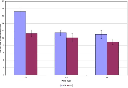
Figure 2.1: Thickness swell measured after 2 hours for the wood component of the three panel types (2.3mm punched through, 4.6mm half punched and 6.9mm surface punched) compared to MDF at the respective thicknesses. ... 49
Figure 2.2: Thickness swell measured after 24 hours for the wood component of the three panel types (2.3mm punched through, 4.6mm half punched and 6.9mm surface punched) compared to MDF at the respective thicknesses. ... 50
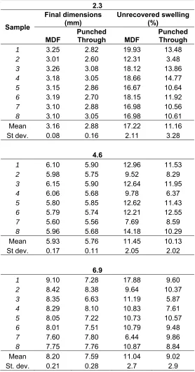
Figure 2.4 : Unrecovered thickness swell of MDF at three different thicknesses and the three
panel treatments (2.3mm punched through, 4.6mm half punched and 6.9mm surface
punched) ... 54
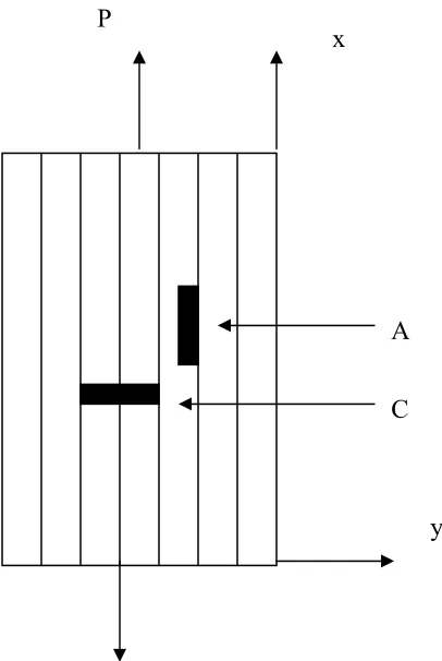
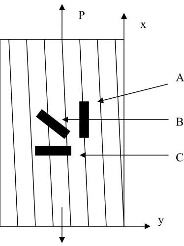
Figure 3.1: Layout of the T-rosette (Figure 3.1a) and rectangular rosette (Figure 3.1b) strain
gauge in the on-axis and 10 degree off-axis test specimens respectively. P denotes the applied force. A, B and C indicates the x, 45 degree and y gages found on the rosettes respectively. 83
Figure 3.2: Stress strain curve for a representative sample of the wood fiber core obtained
from the wood-bicomponent fiber panels ... 90
Figure 3.3: Strains calculated with the macromechanical model by varying the mean
longitudinal elasticity of the bicomponent fiber (E1) by 2 standard deviation increments,
expressed as a percentage of the values obtained using the mean elasticity. A standard
deviation of 1.19E+08 Pa was used. ... 95
Figure 3.4: Strains calculated with the macromechanical model by varying the mean lateral
elasticity of the bicomponent fiber (E2) by 2 standard deviation increments, expressed as a
percentage of the values obtained using the mean elasticity. A standard deviation of
8.66E+07Pa was used. ... 97
Figure 3.5: Strains calculated with the macromechanical model by varying the mean
Poisson’s ratio of the wood fiber core (ν) by 2 standard deviation increments, expressed as a percentage of the values obtained using the mean elasticity. A standard deviation of 0.03 was used. ... 97
Figure 3.6: Strains calculated with the macromechanical model by varying the mean
elasticity of the wood fiber core (E) by 2 standard deviation increments, expressed as a percentage of the values obtained using the mean elasticity. A standard deviation of
4.50E+07 was used ... 98
Figure 3.7: Strains calculated with the macromechanical model by varying the mean
thickness of the bicomponent fiber reinforcement by 0.1 mm increments, expressed as a percentage of the values obtained using the mean elasticity. ... 99
Figure 3.8: Value of E1 where the measured and calculated longitudinal strain converges.
The convergence value is indicated as in the figure as Converged. The mean modulus, as well as the moduli 2, 4 and 6 standard deviations from the mean are also shown. ... 100
Figure 3.9: Value of E where the measured and calculated longitudinal strain converges. The
convergence value is indicated as in the figure as Converged. The mean modulus, as well as the moduli 2, 4 and 6 standard deviations from the mean are also shown. ... 101
Figure 3.10: Value of E2 where the measured and calculated longitudinal strain converges.
The convergence value is indicated as in the figure as Converged. The mean modulus, as well as the moduli 2, 4 and 6 standard deviations from the mean are also shown. ... 102
Figure 3.11: Value of ν where the measured and calculated longitudinal strain converges.
The convergence value is indicated as in the figure as Converged. The mean modulus, as well as the moduli 2, 4 and 6 standard deviations from the mean are also shown. ... 103
Figure 4.1: Comparison of the predicted and measured dimensional changes in the
composite for the longitudinal (x) and crossdirectional (y) directions for three moisture levels ... 123
wood-Figure 5.2: Shift factors obtained for a representative sample of a wood-bicomponent fiber
composite ... 138
Figure 5.3: Creep mastercurve for strain data of a representative sample of a
wood-bicomponent fiber composite. ... 139
Figure 5.4: Long term creep behavior of the bicomponent fiber sheet, the wood-bicomponent
fiber composite and MDF as determined by TTS. ... 140
Figure 5.5: Normalized long term creep behavior of the bicomponent fiber sheet, the
List of Tables
Table A2.1: Thickness swell observed in bicomponent fiber sheets after 2 and 24 hour
submersion tests ... 57
Table A2.2: Dimensions measured for 2 and 24 hour submersion swelling tests for MDF and
the three configurations of wood-bicomponent fiber panels investigated in this Chapter .... 58
Table A2.3: Final dimensions after redrying MDF and wood-bicomponent fiber panel
samples ... 59
Table A2.4: SAS output for data obtained from thickness swelling tests of a
wood-bicomponent fiber composite ... 60
Table 3.1: Elastic moduli (E1 and E2), shear modulus (G12) and Poisson’s ratio (v21)) for the
delaminated bicomponent sheets ... 91
Table 3.2: Comparison of the strains measured during on axis tensile tests with the strains
calculated at arbitrary stresses for each of the bicomponent panels tested. ... 93
Table A3.1: Modulus of elasticity (E), Poisson’s ratio (ν) and shear modulus (G), along with summary statistics, of the delaminated wood fiber core obtained from wood-bicomponent laminate panel 1 through 15 ... 108
Table A3.2: Strains, stresses and Poisson’s ratios (ν12) used to calculated the elastic
constants of a delaminated bicomponent fiber sheet. ... 109
Table 4.1: Elastic moduli (E1, E2, and E), shear moduli (G12 and G), and Poisson’s ratio (ν12
and ν), obtained from delaminated bicomponent fiber sheets and their respective wood fiber cores ... 118
Table 4.2: Thicknesses of the panels and lamina obtained from delaminated bicomponent
fiber sheets and their respective wood fiber cores. ... 118
Table 4.3: Longitudinal (αl) and cross-directional (αw) coefficients of moisture expansion in
MDF at the three EMC’s; standard deviation in brackets ... 120
Table 4.4: Predicted and measured final dimensions of bicomponent fiber panels at different
moisture conditions ... 121
Table 4.5: Longitudinal (αl) and cross-directional (αw) coefficients of moisture expansion in
bicomponent reinforced panels at the three EMC’s; standard deviation in brackets ... 124
Table A4.1: Data obtained from MDF used to determine coefficient of moisture expansion
... 127
Table A4.2: The predicted and measured relative dimensional changes in the longitudinal
Chapter 1: Development of a Wood-Bicomponent Fiber Composite
Abstract
The feasibility of manufacturing engineered wood composites with nonwoven textile
technology was investigated. Needlepunching is a nonwoven textile process which converts
fiber mats into coherent fabric structures with a three dimensional character. This is done by
means of barbed needles, which oscillate in a vertical or slanted direction with regards to the
surface of the fiber mat. Hardwood fiber was blended with 10% urea formaldehyde and
formed into mats (2.3, 4.6 and 6.9 mm thick) with target densities of 550 and 640 kg/m3. The mats were then sandwiched with polypropylene / polyester bicomponent fiber webs and
passed through a needleloom. The barbed needles mechanically bonded the bicomponent
web to the wood fiber mat, and pulled some of the polymer fibers through the thickness
direction of the mat. The mats were then pressed until the urea formaldehyde was fully cured.
Properties of the needlepunched wood composite were qualitatively assessed and compared
to medium density fiberboard (MDF). An average increase in storage modulus of 40 percent
was observed for the 640 kg/m3 panels and 48 percent for the 550 kg/m3 panels.
1.1) Introduction
Medium density fiberboard (MDF) is a wood based composite material that draws on
the usage of wood fibres, rather than particles or veneers to produce board or sheet products
furniture manufacture, cabinet making, joinery, craft work and flooring. Its advantages
include relatively high strength, ease of machining and the ability to be made from a wide
variety of fibrous products. Its use as a structural product has, however, been limited by
unacceptable weathering properties, particularly thickness swell as a result of moisture
fluctuation.
Recently, technology has evolved for combining wood fiber and flour with plastics to
make panel and molded products. Polypropylene and polyethylene are most commonly used
due to cost, ease of processing and relative compatibility with wood fibers. According to
Pirvu et al. (2004), fiber reinforced composites are found in a wide range of applications due
to their high strength and stiffness. Recent studies have shown that fiber reinforced wood and
wood-based materials show great promise as structural components in applications like
bridge decking and beams. Attempts have also been made to incorporate stronger polymer
fibers into a wood product, but these have been limited by problems associated with wood
fiber and polymer adhesion (Gillahm et al., 2000; Park and Seo, 1993; Youngvist et al.,
1992).
Fibers from polymer blends have been increasingly used to modify the physical properties of
fabrics. These bicomponent fibers consist of at least two components, running parallel in the
fiber throughout the length. Each of the components of the fiber retains its own characteristic
properties. This research will focus on polypropylene / polyester bicomponent fibers used in
the nonwoven textile industry and investigate the feasibility of incorporating these fibers into
1.2) Background
1.2.1) Needlepunching
Needlepunching was developed in the late 1800s for producing carpet underlays and
spring padding of mattresses and furniture from coarse animal hair and vegetable fibers
(Hearle, 1972). The technology was adopted in the 1930’s by the automotive industry, while
it was widely adopted by the textile industry in the 1950’s (Purdy, 1980).
Needlepunching is a process for converting fiber webs into coherent fabric structures
(Krcma, 1971). This is done by means of barbed needles, which oscillate in a vertical or
slanted direction with regards to the surface of the fiber web (Mrstina and Fejgl 1990). The
barbed needles repeatedly penetrate or punch into the fiber web, reorienting fibers from the
horizontal to the vertical plane (Figure 1.1). The vertical structure of the fabric consists of
tufts of fiber pulled down through the web by the needles, while the horizontal structure
consists of fibers following curved paths around these tufts (Lennox-Kerr 1972). This
reorientation of some fibers in the vertical plane and the presence of fibers in both planes
produce a coherent structure with improved mechanical properties (Mrstina and Fejgl 1990).
The lateral disturbance of fibers not directly involved with needles is also an important factor
in the formation of a fabric which is resistant to stressing (Purdy 1980). Both natural fibers,
such as wool, cotton, jute and sisal, and synthetic fibers, such as polypropylene,
polyethylene, rayon and nylon, have been used in manufacturing needle punched fabrics or
Figure 1.1: Action of the needle during needlepunching (Dedov 2008).
1.2.1.1) Components involved in needling
As illustrated in Figure 1.2 the web from a web forming system is fed into the loom
by means of feed rolls. If the web is too bulky to fit into the working part of the loom, it is
first passed through a converging channel or a pair of consolidating rollers to partially
compress it (Batra et al. 2003). It is then passed through a horizontal channel formed by the
Figure 1.2: A diagram of a double arbor needle loom (Kamath et al. 2004).
The needles are inserted and held in a needle board. The needles are arranged in the
needle board in rows extending along the width of the board (Batra et al. 2003). Spacing of
the needles relative to each other in the board may differ depending on the nature of the
needles and the products being produced. The needle board then fits into the needle beam
that holds the needle board into place (Mcdonald, 1971). The vertical motion of the beam,
which drives the needles in and out of the web, is applied by means of an eccentric crank
mechanism (Batra et al. 2003). In the down stroke mode, the needles descend through the
stripper plate, through the web and through the bed plate. Corresponding holes are located in
each plate and it is through these holes the needles pass in and out (Hyungsup, 1998). The
name implies; it strips the fibers from the needle so the material can advance through the
needle loom (Batra et al. 2003).
According to Batra et al. (2003), the needling process can be done with a single or
multiple beam looms. By placing multiple beams in a row on the same pass of the fabric,
manufacturers can increase the needling density without decreasing the throughput speed.
Another aspect to be considered is the formation of trumpet-shaped fiber arrangements
caused by the action of the needles. During the descending action of the needle, the barbs
pick up fibers from the surface as well as through the cross section of the web and push them
towards the back. When the needles retract, the reoriented fibers are generally left
undisturbed in their new position, creating a trumpet shape. If the web is only subjected to
one-sided needling, one of the faces will be smooth, while the other will appear fuzzy. To
overcome this problem, the web is needled from both sides (symmetric needling).
1.2.1.2) Needle design and choice
The choice of needle can make or break the needle punched product. The proper
selection of gauge, barb, point type and blade shape (pinch blade, star blade, conical) is
critical in both manufacturing and the final quality of the product (Kamath et al. 2004).
The gauge of the needles is defined as the number of needles that can be fitted in a square
inch area. Thus, the finer the needles, the higher the gauge of the needles. Coarse fibers and
crude products use lower gauge needles, and fine fibers and delicate fibers use higher gauge
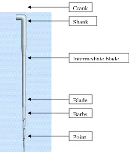
According to Kamath et al. (2004), the major components of the basic felting needle are
as follows (Figure 1.3):
• The crank: The crank is the 90 degree bend on the top of the needle. It seats the
needle when inserted into the needle board.
• The shank: The shank is the thickest part of the needle. The shank is that part of the
needle that fits directly in the needle board itself.
• The intermediate blade: The intermediate blade is put on fine gauge needles to make
them more flexible and somewhat easier to put inside the needle board. This is
typically put on 32 gauge needles and finer.
• The blade: The blade is the working part of the needle. The blade is what passes into
the web and is where the all important barbs are placed.
• The barbs: The barbs are the most important part of the needle. It is the barb that
carries and interlocks the fibers The shape and sized of the barbs can dramatically
affect the needled product
• The point: The point is the very tip of the needle. It is important that the point is of
correct proportion and design to ensure minimal needle breakage and maximize
Figure 1.3: A representation of a needle used during needlepunching (Anon 2004)
The length of the working part (blade) of the needle may vary, as well as the amount
and distance between the barbs. The barb shape can either be conventional, radius flow or
rounded. In the past, needles were primarily triangular in shape. To meet the needs of
specialty markets, new shapes such as tri-star, tear drop or crown needles have been
developed (Batra et al. 2003; Kamath et al. 2004; Narejo and Collins, 2002; Mrstina and
Fjeigl, 1990).
The choice of both the needle and needling parameters depend on a variety of factors. Crank
Shank
Intermediate blade
Blade
Barbs
end-properties needs to be considered in conjunction with fiber properties. Fiber properties
such as fiber strength, surface qualities and friction, fiber dimensions and crimp all play a
role in determining needling parameters and choice of needle. There is therefore no definitive
guide to choosing the needle type and design characteristics if all the factors influencing the
process are considered. Needle choice is therefore often determined by trial and error (Batra
et al. 2003; Kamath et al. 2004; Narejo and Collins, 2002; Mrstina and Fjeigl, 1990).
1.2.1.3) Mechanical effect of needlepunching
Before needling, the fibers in the un-bonded web lie in layers parallel to the plane of
the web and have very few intra-layer fiber entanglements (Batra et al, 2003). The
mechanical properties of needle-punched nonwoven fabrics depend on the fiber entanglement
effected by the needles. The needle barbs catch the fibers during punching and lead them into
the thickness direction, creating fiber-to-fiber entanglement (Watanabe et al. 2005). The
tensile properties of a needle-punched nonwoven are determined by its structural parameters
and fiber properties. When a needlepunched web is subjected to in-plane tensile forces, the
entangled fibers interlock due to frictional forces and resist slippage (Batra et al. 2003,
Hearle, 1972). This mechanism is the primary source of the web strength.
According to Batra et al. (2003), it is well known that the larger the number of fibers
caught by the needle, the greater entanglement of the fibers and the stronger the nonwoven. If
the needle is extremely thick, the barbs catch too many fibers and lead them into the
excessive rearrangement of fibers in the web. Punch density is calculated as follows (Batra et
al. 2003):
v ns
d = Eq. 1.1
Where: d = punch density (punches/m2)
n = number of needles per unit length of the needle board (needles/m)
s = number of strokes per unit time (punches/minute)
v = rate of fabric delivery (m/minute)
In practice, the end use determines the desired fiber characteristics, basis weight of
the web and the punch density required to obtain the optimal performance.
The process is used with webs made from both staple and continuous filament fibers.
Depending on the fiber type and dimensions, the web basis weight and the processing
parameters conventionally needled fabrics can display a range of strength characteristics, is
generally quite resistant to tear or puncture damage.
Needlepunching a web inherently produces a structure that resists lateral (z-direction)
crushing (Batra et al. 2003, Hearle, 1971). It also develops a graduation of fiber densities
through the thickness. In a symmetrically needled fabric, the fiber density near the surface is
to permit fluid flow in the plane of the fabric and makes needlepunched fabrics ideal for
geotextile applications (Batra et al. 2003).
The following properties of needlepunched fabrics were listed by Mansfield (2005):
• Controlled fiber orientation in the machine or cross-machine direction, or at an
intermediate angle
• Z-directional strength, which improves shear strength and reduces the potential for
ply delamination
• High void volumes for easy absorption of resins
• Cost-effective thickness of composite structures by reducing the number of plies,
weight, lay-up times and overall costs
• Ease of blending diverse fibers and fiber structures such as high-strength and
thermoplastic fibers during the needlepunching process
• Distinct batt layering of two or more layers of distinct fiber types in one needlefelt,
and the ability to incorporate lightweight woven fabrics, films and other fabric forms
into the needlefelt structure
1.2.1.4) Needle breakage
Needles can break due to a number of factors. Broken needles not only influence the
quality of the final product due to the presence of needle tips in the material, but also the
entire process performance. A large number of broken needles lead to maintenance downtime
and additional costs in replacing the needles. It is therefore important to identify and rectify
the causes of needles breaking. The following factors influence needle breakage (Anon
2004):
• Needle alignment: If the needle board is not aligned so the needles locate in the middle of
the bed plate hole, breakage is likely
• The fiber quality can often cause needle breakage, especially when needlepunching waste
and regenerated fibers.
• Unopened fiber particles can often break the needles or build up in the bed plate holes of
the needle loom.
• Needling parameters, such as advance per stroke and punch density.
• Aggressive needling: If the barbs are too deep the load on the needle's blade can be too
great and break the needles
• Old needle looms often cause vibration and or poor alignment that can lead to needle
breakage, especially with fine gauge needles.
• Worn needle boards and worn inserts can cause the needles to be too loose in the needle
• Uneven mass distribution in the web will lead to uneven stresses on the needle.
To minimize stresses and the resulting needle breakage, as well as to develop the desired
structure of the finished product, proper size and shape of the needle is very important. There
are now specialized needles available not only for different types of products, but also for
different product weights (Narejo and Collins, 2002). Figure 1.4 illustrates a conical blade
needle designed by Foster Needle Co. which is specifically designed for needling of coarser
material where breakage is likely (http://www.fosterneedleusa.com/prd/ConicalBlade.html).
Figure 1.4: Conical shaped needle designed by Foster Needling Co.
As mentioned previously, needle breakage is also the result of uneven mass
the greater the variation of stresses on the needle. Advances in fiber distribution control
mechanisms have made it possible to manufacture products with uniform mass distribution
which enable the manufacturer to control the stresses exerted on the needles during punching
(Narejo and Collins, 2002).
Another important variable which influences the quality of the finish is the advance
per stroke of the material (Narejo and Collins, 2002). The needles move in a vertical motion,
while the web is pulled horizontally. The speed of the web through the loom is determined by
how much distortion the web and the needles can absorb. In general, the higher the web
penetration and web speed, the greater the stress on the needles. To compensate for this
effect, needleboard manufacturers have developed an elliptical needle path (Narejo and
Collins, 2002). The elliptical nature incorporates both a vertical and horizontal component in
the stroke path, which allows the needle to move horizontally with the web. This leads to
higher throughput speeds and less needle breakage.
1.2.2) Bicomponent Fiber
Bicomponent fibers are formed by extruding two polymers from the same spinneret
with both polymers contained within the same filament. Bicomponent fibers were introduced
by Dupont (Jangala and Kotra, 2004) in themid 1960s. This was a side-by-side hosiery yarn
called "cantrese" and was made from two nylon polymers, which, on retraction, formed a
highly coiled elastic fiber. In the 1970s, various bicomponent fibers began to be made in
phases of fiber production, limiting their use. In 1989, however, a novel approach was
developed using thin flat plates with holes and grooves to route the polymers (Kikutani, et
al., 1996). This process was very flexible and quite cost effective.
A wide range of polymers are used to manufacture bicomponents, including
polyester, nylon 6,6, polypropylene and co-polyamides. The main objective of producing
bicomponent fibers is to exploit capabilities not existing in either polymer alone. By this
technique, it is possible to produce fibers of any cross sectional shape or geometry that can
be imagined. Bicomponent fibers are commonly classified by their fiber cross-section
structures as side-by-side, sheath-core, islands-in-the-sea and segmented-pie cross-section
types.
Figure 1.5 illustrates examples of the four different fiber types. Side-by-side
bicomponent fibers consist of two components divided along the length into two or more
distinct regions. They are generally used as self-crimping fibers. Different melting points on
the sides of the fiber are taken advantage of when fibers are used as bonding fibers in
thermally bonded non-woven webs. Sheath-core bicomponent fibers are those fibers where
one of the components (core) is fully surrounded by the second component (sheath). These
fibers are widely used as bonding fibers in nonwoven industry. The sheath of the fiber is of a
lower melting point than the core and so in an elevated temperature, the sheath melts,
creating bonding pints with adjacent fibers - either bicomponent or monocomponent.
Islands-in-the-sea bicomponent fibers contain areas of one polymer in a matrix of a second polymer.
Figure 1.5a: Side-by-side bicomponent fiber
Figure 1.5b: Sheath-core bicomponent fiber
Figure 1.5c: Islands-in-the-sea bicomponent fiber
Polyester has a specific gravity which can range from 1.26 to 1.34, with a flexural
modulus of 1400 to 2690 MPa, depending on the formulation used and the supplier.
Polypropylene has a reported specific gravity of 0.899 to 0.901, with a flexural modulus of
694 to 2190 MPa (Perry and Green 1997). Glass transitions for the respective polymers are
69 and -18oC respectively.
1.2.3) Medium Density Fiberboard (MDF)
MDF consists of wood fibers (including; tracheids in softwoods, and vessels, fibres,
fiber-tracheids and parenchyma cells in hardwood (Evans, 1994)) blended with synthetic
thermosetting formaldehyde based resins and then pressed into boards. MDF can be made
from a wide variety of lignocellulosic materials and an important implication of this is the
use of recycled materials and non-wood fibres in its manufacture. Many softwoods and even
bamboo (Wang, 1991), rice husks and waste paper (Dube, 1995) have been used successfully
in the manufacture of MDF, although the type of fiber used in its manufacture strongly
influence board properties (Myers, 1983). Combinations of wood and non-wood materials
are increasingly being used to enhance specific properties, particularly strength, density and
sorption characteristics (Park, 1993). MDF is increasingly being used as a replacement for
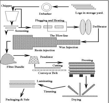
other wood products, and its use in engineering fields is increasing. Figure 1.6 illustrates the
Figure 1.6: A schematic representation of an industrial MDF manufacturing process (Beutel,
1996)
Once the MDF plant has obtained suitable logs, the first process is debarking. The
logs could be used with the bark, as could any fibrous material, but for optimisation of the
final product the bark is removed to decrease equipment damaging grit, allow faster drainage
of water during mat formation, decrease organic waste load by 10-15 %, stabilize pH levels
(reduces corrosion of tools ) and increase surface finish. Although some plants accept chips
containing anything from four to sixteen blades, is used. The blades are arranged radially on
a plate and the spinning plate is faced perpendicularly to the log feed. The feed speed of the
logs, the radial speed of the knife plate, the protrusion distance of the knives and the angle of
the knives, control the chip size. The chips are then screened and those that are oversized
may be rechipped. The chips can be pulped using a Masonite gun process, atmospheric or
pressurized disk refiner. After defibration fibers enter the blow line. The blow line is initially
only 40mm in diameter with the fibers passing through at high velocity. Wax, used to
improve the moisture resistance of the finished board, and resin are added in the blow line
while the fibers are still wet, as dry fibers would form bundles, due to hydro bonding, and
material consistency would be lost. The fibers are dried by heating coils warming the
blowline to about 6-12 percent moisture content. After drying, mat formation is
accomplished by means of airlaying. The mat can either be laterally cut to size as it leaves
the pendistor or it can be cut half way through its run by a synchronised flying cut off saw.
The density profile of the panel is critical to achieving satisfactory strength properties.
Concentrating mass, and hence load bearing ability, at the top and bottom of the board means
that inertial properties are maximized and the greatest strength can be obtained for minimal
weight. This is achieved by the press acting at impacted pressure initially and then slower
pressure application. As an example, for a 16mm board:
• Press closed. 20 seconds to bring mat to 28 mm.
• 28 seconds at 26mm.
• Total time of 330 seconds to bring board to 16mm, then decompression time.
1.3) Materials and methods
Hardwood fibers and urea formaldehyde resin were obtained from DYNEA,
Moncure, North Carolina. The resin mixture and resin/fiber ratios were calculated by means
of the blending spreadsheet used by DYNEA in their in-house testing procedures. Fiber
moisture content was established by oven drying.
Initial separation and blending of the wood fiber with the urea formaldehyde was
done in a rotary drum blender designed and constructed at North Carolina State University.
The blender drum has a diameter of 2 meters, with an atomizing spray nozzle attached in the
center of the drum. After consultation with researchers at DYNEA, a 10 percent resin blend
was decided on with board densities of 550 and 640 kg/m3.
Fiber separation and randomization was accomplished by means of a C.S Bell
Company 10HBML rotary hammermill with a cyclone attachment (Figure 1.7). The purpose
Figure 1.7: C.S. Bell 10HBML hammermill used during this research
(http://www.csbellco.com/hammer.htm).
The cyclone attachment deposited fibers into a 0.61 by 0.30 m forming box. The fiber
was manually fed into the hammermill, with each handful of fibers given adequate time to
pass through the machine and into the forming box to avoid blockage. When all the fiber had
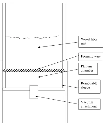
been put into the forming box, the mats were manually precompressed. Figure 1.8 illustrates
Figure 1.8: Design of the forming box used for mat formation.
Wood fiber mat
Forming wire
Removable sleeve
Depending on the target thickness of the board, the average height of the mat was 100
to 250 mm. To reduce the mat height and to densify the mat, the mat was cold-pressed to
approximately 20 to 100 mm using the Bryan 200 prepress. This allowed for easy handling
and insertion into the hot press. Initially, the panels were consolidated using a steam-heated
press. Later experiments were conducted using an electrically heated, manually controlled
Carver 3912 press. The press temperature was approximately 177°C. Panels were pressed
for 3 minutes at a minimum pressure of 68 MPa.
Internal bond strength tests were conducted on 50 by 50 mm samples to ensure that
the MDF met industry requirements. A thermoplastic resin was applied to the surfaces of the
samples, and heated aluminum testing fixtures were adhered. The testing fixtures were
carefully aligned with the grip grooves on both surfaces kept parallel. Samples were tested to
failure in an MTS testing machine in accordance with ASTM D1037 (ASTM 2006).
Due to inadequate bonding between the wood fiber and the PET, it was decided to
switch to a polypropylene / PET bicomponent (BC) fiber, obtained from Fiber Innovation
Technologies, Inc, Knoxville, Tennessee. The fiber length was 38 mm, with a fiber diameter
of 3 denier (+- 0.3 denier). Fiber crimp was 11.0 percent (+- 1.5 %). The sheath melt
temperature was listed as 165oC. A DSC scan was conducted on the raw fiber by means of a TA Q100 differential scanning calorimeter.
The bicomponent fiber arrived in bale form, and was opened, carded and crosslapped to form
Research Center at NCSU. Carding is a web forming process in which the fibers are opened
and parallelized by means of rotating cylinders. The cylinders rotate at different speeds and
have angled needles on the surface which combs the fibers to form a web with a distinct fiber
orientation. The resultant bicomponent fiber web produced by the card had a very low basis
weight, and it was decided to crosslap the material Crosslapping involves a pendulum
conveyor which lays the web in to folds onto a conveyor belt. A low crosslapping angle was
employed in order to maintain fiber orientation in the final product. A fiber orientation
distribution analyses was conducted using a Fast Fourier Transform on backscattered light
obtained from images of the nonwoven taken by a light microscope.
Initial experimentation involved the manufacture of a simple sandwich panel with the
bicomponent fiber web on the surfaces, and wood fiber in the core. Adhesion between the
polymer and wood fiber was found to be lower than desired and it was determined that the
additional mechanical interlocking achieved with a needleloom was needed in order to ensure
panel integrity. The needleloom used was James Hunter Machine Co. pilot scale loom.
Needles were obtained from Foster Needle, Manitowoc WI.
Sample beams with dimensions of 12.5 by 50 mm were cut with a table saw from the
different panels made in this study. These beams were tested in a TA Q800 Dynamic
mechanical analyzer (DMA) with a double cantilever testing jig. A first set of samples were
cut with the fiber alignment along the longitudinal axis (L) of the beams, and a second set
was cut with fibers aligned perpendicular to the longitudinal access (C). Samples were
measured and the samples were weighed. Three samples per panel falling within 3 percent of
the target densities were selected for testing. A set strain of 0.5% was applied to the samples
at a frequency of 1 Hz and the storage modulus was measured. The temperature in the
chamber was kept constant at 26oC. MDF panels were prepared and tested in conjunction with the laminate panels for comparison purposes.
1.4) Results and discussion
Experiments with MDF were conducted to determine the limitations of the
experimental setup. Internal bond strength (IB) is a widely accepted industry standard to
determine board properties. The boards manufactured during this research had an IB of 0.83
MPa (+- 0.2 MPa), which compared favorably with the results obtained by Xing et al. (2007)
who listed IB values of between 0.67 and 1.2 MPa. The American National Standards
Institute lists a minimum IB strength of 0.6 MPa for MDF (ANSI A208.2).
Figure 1.9 illustrates the results obtained from the fiber orientation distribution
analyses conducted on the bicomponent fiber web. It can be seen that the web displays a
higher degree of orientation with regards to the machine direction. The bimodal distribution
is the result of crosslapping after the web is carded. This is in agreement with a fiber
orientation analyses conducted by Ramal (2006) on webs produced with a 5o cross lapping angle. This allowed control over the fiber orientation in the polymer webs when the
0.000 2.000 4.000 6.000 8.000 10.000 12.000
0 20 40 60 80 100 120 140 160
Orientation Angle (degrees)
R
el
at
iv
e Fr
eque
nc
y (
%
)
Figure 1.9: Fiber orientation distribution of the polypropylene / polyester bicomponent
nonwoven fiber web used as reinforcement of a wood fiber composite.
Two panel products were considered for this research. The first consisted of wood /
polymer fiber blend. This idea was discarded after initial attempts failed to obtain a
homogenous blend in the rotary drum blending.
Initial experimentation involved determining whether the needlepunching process can
successfully be applied to a wood fiber mat. It was quickly determined that wood fiber is two
short to needlepunch. A longer carrier fiber was needed in order to insure the integrity of the
fiber mat during the process and for adequate fiber entanglement.
The second panel product was a needlepunched composite laminate panel with a
investigate the feasibility of the research method were conducted using polyester webs (PET)
obtained from the Nonwoven Cooperative Research Center (NCRC) at NCSU. The webs
used had basis weights of 60 and 100 grams per square meter (gsm) respectively. Figure 1.10
illustrates the panel obtained using a polyester web.
Figure 1.10: Wood-polyester fiber panels manufactured during initial phases of the project.
The biggest issue considered was to obtain the thickest possible final panel thickness
at the desired panel density, while still adhering to the limitations of the needlepunching
process. The needleloom used had a throat height of approximately 30 mm. Initial runs on
the loom with approximately 7475 gsm wood fiber webs prepressed to less than 30 mm
resulted in an excessive amount of needles breaking. In order to optimize the needle design
weights of 4485, 2990, 1495, 748 and 500 gsm respectively. Unfortunately, good records
were not kept of the specific needles used, but the following will briefly describe how the
needle choice was influenced.
The first runs on the loom were conducted using thin, 9 barb needles which were
already present in the needleboard. The needle was only successful in punching the 500 gsm
mats. To obtain the target densities of 550 and 640 kg/m3 with a 500 gsm mat will result in a
panel with final dimensions too thin for testing with conventional methods used in
characterizing MDF. It was suggested that the needle damage might be caused by excess
fibers being captured from the polyester webs on the surfaces. A thin 6 barb needle was tried,
with similar results as observed with the 9 barb needle. An extremely thick carpeting needle
managed to survive the punching process at all the basis weights, but, unfortunately, the fiber
mats did not. Too much of the polyester fibers were captured, which resulted in the wood
fiber breaking through the surfaces and the mat loosing integrity. Intermediate 9 and 6 barb
needles failed as well. A stronger alloy needle used to punch kenaf fiber was investigated
next. It performed well at 500 and 748 gsm, but both basis weights would still result in
inadequate final panel thicknesses at the desired panel densities. An intermediate alloy needle
was attempted with limited success up to 1495 gsm. A basis weight of 1495 gsm at 640kg/m3 will result in a final panel thickness of 2.3 mm which was considered adequate. A conical
blade 9 barb needle (F 20 9-20-3B) with a triangular crossection proved to be the most
successful. hicker alloy needles were investigated, but they experienced similar problems as
Panels were differentiated according to punching depth. For the first panel type, the
carded web was placed on top of 1495 gsm wood fiber and needlepunched (Figure 1.11).
This provided adequate bonding for the surface laminate. Two of these needlepunched webs
were then used to sandwich resinated wood fiber before consolidation in the press. The final
panel thickness for this configuration was 6.9 mm.
6.9 mm panel
Oscillating needleboard with needles
Oscillating needleboard with needles
Resinated wood fiber Resinated wood fiber Bicomponent fiber web
Figure 1.11: The 6.9 mm surface punched panels illustrating the different layers of the
composite, and the areas affected by needling.
In the second panel type, a 1495 gsm wood fiber web was needlepunched in
conjunction with a bicomponent web (Figure 1.12). Two needlepunched mats were placed on
top of each other with the wood fiber facing the center. The final panel thickness after
4.6 mm panel 4.6 mm panel
Figure 1.12: Illustration of a 4.6 mm half punched wood-bicomponent fiber panel.
The third was a sandwich panel containing a 1495 gsm wood fiber web punched all
the way through with bicomponent fiber placed on both sides of the wood fiber mat (Figure
1.13). The panels were punched from both sides and had a final thickness after pressing of
2.3 mm.
2.3 mm panel 2.3 mm panel
The fiber alignment in the bicomponent webs were carefully noted and controlled
during the formation of the panels with both surfaces of the panels having the same fiber
Figure 1.14a: Unconsolidated 4.3 mm half punched wood-bicomponent fiber panel.
Figure 1.14b: Consolidated wood-bicomponent fiber panels.
Figure 1.14: Unconsolidated and consolidated wood-bicomponent fiber panels manufactured
To further investigate the interaction between the bicomponent and wood fibers,
samples were prepared for imaging on a scanning electron microscope. The samples were
first desiccated to a moisture content of 0 percent, prior to being sputter coated with gold.
Figure 1.15 shows a bicomponent fiber tuft pulled from one surface through the wood fiber
core, illustrating the action of the needles during punching. Figure 1.16 illustrates the
interface between the surface reinforcement and the wood core. A wood fiber can be
observed at the center of the scan, with a bicomponent fiber adjacent to it.
Figure 1.16: SEM scan of a wood fiber at the wood fiber / bicomponent fiber interface
Figure 1.17 illustrates a representative graph obtained from the DSC scan of the raw
bicomponent fiber. The melting point of the polypropylene sheath can be observed at 165oC, and that of the polyester core at 250oC, which is in agreement with results publish by Perry and Green (1997). This shows that the polypropylene sheath will melt and fuse with the
DSC Scan of PP / PET Bicomponent Fiber
-18 -16 -14 -12 -10 -8 -6 -4 -2 0
50 83 117 150 183 217 250 283
Temperature (oC)
H
ea
t Flow (
m
W)
Figure 1.17: DSC scan of polypropylene / polyester bicomponent fiber showing the melting
point of both polymer components.
Figure 1.18 illustrates the results obtained for the storage modulus of the 550 kg/ m3 panels with the DMA. The mean storage modulus of all three MDF panel thicknesses were
392 MPa (Coefficient of variation (CV) 2.8 percent), while no significant difference in
storage modulus was found between panel thicknesses. The mean storage modulus of the 2.3
mm punched through wood-bicomponent fiber laminate panel with the bicomponent fibers
aligned along the longitudinal axis was found to be 563 MPa (CV 5.2 percent), while the
5.1 percent) and 501 (CV 4.5 percent) MPA respectively. All three values were significantly
different from that obtained with MDF of the respective thicknesses. The storage modulus
obtained from the 2.3 mm samples were, however, 11 percent higher than that obtained from
the 4.6 and 6.9 mm samples. This can be attributed to the fact that the bicomponent fiber
sheet is stiffer than MDF (see Chapter 3), and has a greater influence on the overall stiffness
of the thin panels
Comparison Between Punch Types and MDF with a Board Density of 550 kg/m3
0 100 200 300 400 500 600 700 800
2.3mm 4.6mm 6.9mm
Panel Types
S
to
rag
e M
o
d
u
lu
s (
M
P
a)
MDF550 L550 C550
Figure 1.18: Storage modulus comparison of MDF with a board density of 550 kg/m3
The storage modulus calculated when the bicomponent fibers aligned perpendicular
to the longitudinal axis of the beams was found to be higher than that obtained from the
longitudinally aligned fibers. Similar trends were observed with the cross-directional fibers,
with the 2.3 mm panels having a significantly higher storage modulus than the 4.6 and 6.9
mm panels. The storage modulus for the 2.3, 4.6 and 6.9 mm panels were 683 (CV 5.8
percent), 581 (CV 8 percent) and 589 (CV 4.5 percent) MPa respectively. Further
investigation is needed to determine why the longitudinal modulus is lower than the
crossdirectional modulus.
Figure 1.19 illustrates the results of storage modulus measurements obtained from the
640 kg/m3 panels. The results were similar as those obtained with the 550 kg/m3 panels. An overall increase in storage modulus of 10 percent was observed due to the higher panel
density. The relative difference between the storage modulus of the laminate panels and
MDF was lower in the case of the 640 kg/m3 panels than for the 550 kg/m3 panels. This can be attributed to the greater influence of the lower stiffness wood fiber composite in the 640
kg/m3 panels. Furthermore, there is an overall increase in the storage moduli with an increase in panel density. This is in agreement with Wu and Suchland (1998), who found that MOE
Comparison Between Punch Types and MDF with a Board Density of 640 kg/m3
0 100 200 300 400 500 600 700 800 900
2.3mm 4.6mm 6.9mm
Board Types
S
tor
ag
e M
odul
us (
M
P
a)
MDF640 L640 C640
Figure 1.19: Storage modulus comparison of MDF with a board density of 640 kg/m3
(MDF640) and wood-bicomponent fiber panels with bicomponent fiber alignment along (L640) and across (C640) the testing beam length and for three punch types (2.3mm, 4.6mm and 6.9mm)
1.5) Conclusion
Attempts have been made by the wood composites industry to blend a high strength
fiber into a wood fiber panel product with some success. They are, however, limited by the
difficulty of obtaining adequate wood fiber / polymer adhesion. Nonwoven textile
technologies such as needlepunching and the use of bicomponent fibers could prove to be a
Polypropylene is commonly used to produce wood plastic composites and have been shown
to form weak bond with wood flour. When hot-pressing the polypropylene / polyester (PP /
PET) bicomponent fiber, the melt temperature of the polyester is not reached. PP, however,
melts at approximately 165oC. When incorporated into a wood fiber product, the PET component will remain intact, while the PP will melt and infuse into the wood fiber. This,
along with the fiber rearrangement resulting from needlepunching, mechanically bonds the
polyester fiber to the wood. The overall stiffnesses of the wood-bicomponent fiber laminate
panels were found to be was significantly higher than that obtained from MDF.
The needlepunching process shows considerable promise for incorporation in an
industrial setting. To overcome the problems of low final product thickness, minor
1.6) References
American Society for Testing and Materials (ASTM). 2006. Standard methods for evaluating properties of wood-based fiber and particle panel materials. D1037. American Society for Testing and Materials, West Conshohocken, PA.
Anon. Why do needles break? Technical note, Foster Needles USA.
Batra, S.K., B. Pourdeyhimi and D. Shiffler. 2003. TT305: Fiberweb and nonwoven production. Classnotes.
Bosak, D.R., A.A. Ogale and J. van Dun. 2005. Bicomponent fibers derived from immiscible polymer blends. Textile Research Journal 75(1): 50-56.
Datla, V.M. 2002. The influence of fiber properties and processing conditions on the characeteristics of needlefelted fabrics. Masters thesis. North Carolina State University, Raleigh, North Carolina.
Dedov, A.V. 2008. Estimation of air permeability of needlepunch materials. Fiber Chemistry 39(6): 23-25
Gillahm P.R., M.A. Irle and S.A. Amartey, 2000. Development and production of laboratory scale novel MDF panels from composite and nonwoven mattresses of sisal and wood fiber mixtures. Holz Als Roh- und Werkstoff 58(5): 324-330.
Guess, F. M., D.J. Edwards, T.M Pickrell, and T.M. Young. 2003. Exploring
graphically and statistically the reliability of medium density fiberboard. International Journal of Reliability and Applications 4(4): 97-110.
Hearle, J.W.S., 1972. A theory of the mechanics of needled fabrics. From: Needle-felted fabrics, Ed. P. Lennox-Kerr. W.R.C. Smith Publishing Co., Atlanta, Ga.
Hegde, R.R., A. Dahiya and M.G. Kamath. 2004. Bicomponent fibers.
(2005).
Huntoon, R. 1990. The needlepunch handbook . NCINDA, Cary, NC.
Hyungsup, K. 1998. Study of needlepunching process and products. Ph.D thesis, North Carolina State University, Raleigh, North Carolina.
Kamath M.G., A. Dahiya and R.R. Hegde. 2004. Needlepunched nonwovens.
Krcma, R., 1971. Manual of nonwovens. R.C. Smith Publishing Co., Atlanta, Ga.
Kiekens, P. and M. Zamfir. 2002. Non-wovens from cotton fibers for absorbent products obtained by the needle-punching process. AUTEX Research Journal 2(4): 166-174.
Lennox-Kerr, P. 1972. Needle felted fabrics. W. R. C. Smith Pub. Co, Atlanta, Ga.
Liu, J.Y. and J.D. McNatt. 1991. Thickness swelling and density variation in aspen flakeboards. Wood Science and Technology 25(1): 73-82.
Mansfield, R.G. 2005. Advancing needlepunched nonwovens. GFR Magazine 6.
Mcdonald, M., 1971. Nonwoven fabric technology. Noyes Data Corporation, New Jersey, NJ.
Mrstina, V., and F. Fejgl. 1990. Needle Punching Textile Technology . Textile Science and Technology 14(21):.44-68.
Narejo, D. and L. Collins. 2002. Advances in needlepunching. GFR Magazine 6.
National Particleboard Association. 1994. Medium density fiberboard. ANSI A208.2-1994. NPA, Gaithersburg, MD.
Park, J and S. Seo. 1993. Performances improvement of medium density fiberboard by combining with various non-wood materials. Research Reports of the Forestry Research Institute Seoul 47: 35-48.
Perry, R.H. and D.W. Green. 1997. Perry’s Chemical Engineers Handbook. McGraw Hill, New York, NY.
Pirvu, A., D.J. Gardner and R. Lopez-Anido. 2004. Carbon fiber-vinyl ester reinforcement of wood using the VARTM/SCRIMP fabrication process. Composites Part A: Applied Science and Manufacturing 35(11): 1257-1265.
Purdy, A.T. 1980. Needle Punching. The Textile Institute, London.
Rawal, A. 2006. A modified micromechanical model for the prediction of tensile behavior of nonwoven structures. Journal of Industrial Textiles 36: 133-138.
Chapter 2: Thickness Swelling Characteristics of a Needlepunched Wood-Bicomponent Fiber Composite
Abstract
This study focused on the feasibility of incorporating a polypropylene / polyester
bicomponent fiber web into a wood fiber panel, and the effect this will have on thickness
swell characteristics. Thickness swelling properties were investigated for 3 panel
configurations: a 2.3mm panel with a polypropylene / polyester bicomponent web placed on
each surface and needlepunched from both surfaces with the needles passing through the
entire thickness prior to pressing; a 4.6 mm panel with a polypropylene / polyester
bicomponent web placed on each surface and needlepunched through both surfaces with the
needles passing through half the thickness prior to pressing; and a 6.9 mm panel with a
polypropylene / polyester bicomponent web placed on each surface and needlepunched from
both surfaces with the needles passing through a third of the thickness prior to pressing.
Results were compared to the thickness swelling characteristics of MDF panels with similar
thicknesses as the wood-bicomponent fiber panels investigated. Improvements in thickness
swelling over that of MDF was observed in the 2.3 mm punched through panels and the 4.6
2.1) Introduction
Thickness swelling of wood composites in relation to moisture content (MC) change
and panel manufacturing parameters has been extensively studied. It was shown (Wu and
Piao, 1999; Halligan, 1970; Wu and Suchsland, 1997) that total thickness swelling has two
components: recoverable thickness swell and non-recoverable thickness swell. Recoverable
thickness swelling is due to MC change within the hygroscopic range, while non-recoverable
thickness swell is a result of the combined effect of the compression stress release from the
pressing operation and differential swelling potential due to inherent in-plane density
variation. The latter results in normal swelling stresses between high and low density areas in
the plane of the panel. These stresses are often large enough to break the adhesive bonds,
leading to non-recoverable thickness swelling.
Dimensional stability has been one of the mostly investigated characteristics of wood
and wood-based composites. The hygroscopic nature of the wood material comes from the
hydroxyl groups of the cell wall polymers. Many efforts were made to replace the hydroxyl
groups by less hygroscopic groups.
Rowell et al. (1995, 1989) studied extensively the chemical modification of wood and
wood-based composites by esterification treatments, mainly acetylation (esterification using
acetic anhydride). However, various reports mention that this treatment causes a decrease in
the mechanical properties and other important properties of wood materials (Chow et al.
Currently, the wood-based panel industry uses paraffin waxes to improve the
dimensional stability of the panels. However, the hydrophobic properties of paraffin waxes
have a short-time effect, resulting in a simple delay in water absorption.
Needlepunching utilizes barbed needles to rearrange fibers in a fiber mat from the
horizontal to the vertical position. This mechanically interlocks the fibers and significantly
changes the properties of a fiber web. Furthermore, polypropylene / polyester bicomponent
fiber webs were used as surface reinforcement. Bicomponent fibers are formed by extruding
two polymers from the same spinneret with both polymers contained within the same
filament. The properties affected can be adapted by changing the process parameters and the
polymers involved, resulting in the possibility of an engineered final product. The
bicomponent fiber webs were needlepuched in conjunction with wood fiber mats to form
sandwich panels.
This study focused on the effect of needlepunching on the thickness swell of MDF. It
also investigated the feasibility of incorporating a polypropylene / polyester bicomponent
fiber web into a wood fiber panel, and the effect this will have on thickness swell
characteristics.
2.2) Materials and methods
Wood fibers were prepared and blended as described in Chapter 1. The needleloom
used during the course of this research had a throat height of approximately 30 mm. It was
The configurations investigated were a 2.3 mm punched through panel, a 4.6 mm half
punched panel and a 6.9 mm surface panel descrived in Chapter 1.
Thickness swelling tests were performed according to ASTM D 1037 Method 23A
(ASTM 2006). Eight samples of each panel type were made, in conjunction with 8 MDF
panels as control. Samples were cut (152 mm by 152 mm) with a table saw and conditioned
in a conditioning chamber set at 65 percent relative humidity and a temperature of 20°C for
30 days. Samples were weighed and measured 25.4 mm from the edges after the conditioning
period. Measuring positions were marked prior to measurement. Samples were submersed
horizontally on a plastic grid in 25.4 mm of water and weighed down with additional plastic
grids for 2 hours. The grids allowed free movement of water on all surfaces of the specimens,
while maintaining minimum contact with the samples. Samples were removed from the water
and allowed to drain for 10 minutes prior to measurement of the dimensions and weight. The
process was repeated after a further 22 hours. Samples were oven dried to determine the final
moisture content. A completely randomized split plot design was used, with boards as whole
plot units, treatment and panel thickness as whole plot factors and a subplot factor of time.
To determine the recoverable and unrecoverable thickness swell, the samples were
conditioned at 65 percent relative humidity and a temperature of 20°C for 30 days. Samples
were remeasured, and the nonrecoverable thickness swell was determined based on the
In order to determine what the contribution of the constituents of the composite were
in overall panel thickness swelling, a thickness swelling test was conducted on manually
delaminated bicomponent sheets.
2.3) Results and discussion
The bicomponent sheets were found to swell by approximately 2.7% after a two hour
submersion test, with no increase in thickness swelling found after 24 hours (Table A2.1).
Table A2.2 lists the dimensions observed for the 3 panel configurations described earlier, as
well as MDF manufactured with corresponding thicknesses. A rule of mixtures was used to
back out the contribution of the bicomponent sheets to the overall thickness swell:
Spxp = Smxm + Sbxb Eq. 2.1
where: Si = percentage thickness swell
xi = thickness component of each composite lamina
p, m, b = laminate, wood component and bicomponent sheet component,
respectively
Figure 2.1 illustrates the thickness swell of the wood component of the
wood-bicomponent fiber panels after 2 hours (Sm) and the thickness swell observed in MDF (Table
A2.2). It was found that thickness swell of the MDF decreased with an increase in panel
thickness, showed the greatest difference in measured thickness swell when compared with
the thickness swell of 2.3 mm MDF panels. The difference in thickness swell in the 4.3 mm
needlepunched and MDF panels, which consisted of two fiber mats which were punched
from one side only, essentially resulting in panels which were punched only half way through
the thickness, was relatively smaller. No significant difference in MDF / needlepunched
panel thickness swell was observed in the 6.9 mm panels, where only a surface layer was
punched. The values obtained for MDF are in agreement with those observed by Hashim et
al. (2008) and Widsten et al. (2004) who obtained values after 2 hours of 16.2 and 13.7
percent respectively. Both sets of researchers did not use any additives during their research.
The addition of additives can significantly improve both 2 and 24 hour thickness swell,
however. Ye et al. (2007) observed a value of 5% thickness swell at a resin content of 9%
after addition of 1% wax emulsion to the furnish during blending. Wang et al. (2001)
obtained mats with 9% resin content with 0.25% wax emulsion added from a commercial