Feasibility Analysis of Method to Avoid Tube Rupture in HTR-10 Steam Generator
DONG Jianling, MENG Yang, YU Suyuan, FU Jiyang
Institute of Nuclear Energy Technology, Tsinghua University, Beijing 100084, P. R. of China
ABSTRACT
The 10 MW High Temperature Gas-Cooled Reactor (HTR-10) steam generator tubing is the barrier between the primary loop and the secondary loop. Because the pressure of the primary side is less than that of the secondary side, the water and steam will flow into the primary loop if a tube ruptures and react with the graphite fuel elements and the graphite core internals which will result in destruction of the fuel ball, release of radioactivity into the primary loop and increased primary loop pressure. The HTR-10 steam generator tubes are helical tubes with small curvature so tube cracks cannot be detected by using eddy current detection for volumetric in-service inspection. This paper describes a leakage detection system and demonstrates that the crack whose leakage can be detected by the leakage detection system is stable for normal operation loads and SSE loads. Within the crack stability period, all protection actions of the reactor shutdown protection systems could be completed and the intra-tube pressure decreases to a safe level.
1. INTRODUCTION
The steam generator (SG) heat transfer tubes are the weakest links in the primary loop of a nuclear power plant. Up to 1998, 1000,000 leaking tubes had been plugged. 105 SGs were replaced before 1996 [1]. The actual average life time of SGs is 14 years, with the shortest life being 8 years [2]. For a PWR, heat transfer tube rupture can result in leakage of the primary loop coolant into the secondary loop and pollution to the secondary loop and the environment. The tube rupture is commonly prevented in pressure water reactors by an eddy current detection system for intra-tube pre-service and in-service inspection. If an unacceptable crack is found, the tube will be plugged or repaired with a mounting sleeve. In some cases, the whole steam generator has to be replaced [3].
The l0 MW High Temperature Gas-Cooled Reactor (HTR-10) Steam Generator connects and isolates the primary radioactive helium loop from the secondary non-radioactive water and steam loop. Because the pressure on the secondary side is higher than the helium pressure on the primary side, a heat transfer tube rupture will cause water and stream in the SG to flow into the primary loop, mixing with the helium flow in the reactor core. The increase of steam concentration in the pebble bed enhances the reactor core moderation, which introduces positive reactivity and increases the reactor power and temperature. When a large amount of steam leaks into the primary loop, the iodine deposit on the steam generator is crushed into helium coolant and the incoming steam reacts with the fuel elements and the graphite components at high temperature, which produces water gas. This directly affects the integrity of the graphite components, which release radioactivity to the environment. The expanding gas in the superheated reactor core will increase the primary loop pressure. When the pressure in the reactor exceeds the set pressure of the safety valve in the pressure relief system of the primary loop, the safety valve will open, which will release radioactive products to the reactor building and the atmosphere. Gao et al. [4], in their analysis of a double ended guillotine break (DEGB) of a HTR-10 SG tube showed that the safety valves in the pressure relief system will open and discharge a gas volume equal to 1/4 of the total helium inventory in the primary loop.
The HTR-10 SG heat transfer tube is a small curvature helical tube. The structure prevents intra-tube volumetric inspection. This paper describes a method to avoid tube rupture accidents without using intra-tube volumetric in-service inspection. This paper analyzes the feasibility of the method through stress calculations of the tubing for normal conditions and fault conditions using a fracture mechanics analysis and leak rate calculations. The results show that the leakage detection method can prevent tube rupture accidents although more research work is needed to do before it can be used in practice.
2. HTR-10 SG HEAT TRANSFER TUBE STRUCTURE AND ITS PRE-SERVICE AND IN-SERVICE
INSPECTION
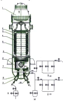
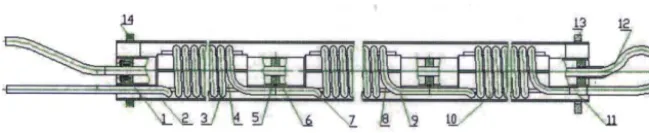
There are 30 sets of heat transfer tubes in the HTR-10 steam generator, which are mounted in the annulus formed by the SG canister and the intermediate heat exchanger (IHX) canister, Figure 1. The heat transfer tube has three sections, the pre-heated section, the phase-change section and the superheated section. The tubes are in sets, each having a single helical tube with a small bending radius wounded around an inner pipe. Each set consists of a central pipe, a helical tube, supports and the external pipe. Four helical tubes sections are supported on the central pipe by tooth-like plates, Figure 2. The first
~ " ~ ?,ii~i!i~ : : ...
three helical tubes sections are pre-heated section and phase-change section with diameters of O 18 mm and thickness of 3 ram, respectively. The final helical tube section is superheated section with a diameter of O 18mm and a thickness 2mm. The tube-bending radius is 56mm. Each helical tube section has 23 turns with a distance between the turns of 22.5mm. Only a pressure test and a helium leakage test are conducted during in-service inspection. The pressure test is conducted on the tube side, while the leakage test is on the shell side. During in-service inspection, tube plates located in the SG tube box are approachable when the tube box header is opened. If the leakage rate is not acceptable, helium leakage inspection equipment can be used to find the leaking tube when the reactor is shut down. The leaking tube can then be plugged on the non-radioactive side in the cold leg tube box and in the hot leg tube box.
12 \
I 13
14
Fig. 1 SG and related systems
1-helium fan; 2-connection tube; 3-heat transfer tube; 4-SG; 5-SG pressure vessel; 6-load bearing plate; 7-the helium purification system inlet; 8-helium purification system outlet, 9-cold leg; 10-hot leg; 11-SG accident discharge system;
12-pressure relief system; 13-gas sampling and gas analysis system; 14-helium purification system.
3. L E A K D E T E C T I O N M E T H O D TO M O N I T O R THE HEAT T R A N S F E R TUBE I N T E G R I T Y
t3 12
Fig. 2 Heat transfer tube set structure
l-lower end plate; 2-external pipe; 3-first helical tube section; 4-internal pipe; 5-fixing ring; 6-central pipe; 7-second helical tube section; 8-support plate; 9-third helical tube section; 10-fourth helical tube section; 11-transition section; 12-connection
tube; 13-upper orientation plate; 14-lower orientation plate.
4. SYSTEMS RELATED TO HEAT TRANSFER TUBE INTEGRITY
4.1 HTR-10 SG heat transfer tube leakage detection humidity-meters
HTR-10 has three sets of sensitive humidity-meters in its gas sampling and analysis system to provide a highly sensitive detection method for monitoring heat transfer tube leakage. The dew point temperature range of the humidity-meters is from -100 °C to +20 °C, which is a moisture content range from 0.0013 ppm to 25000 ppm. During normal reactor operation, the primary loop humidity is less than 2 ppm. The reactor shutdown system will shut down the reactor when tube leakage detected by the humidity system exceeds prescribed limits.
HTR-10 also has other detection systems that are auxiliary tools for detecting tube leakage, such as the neutron flux measuring system and the primary loop thermodynamic parameters measuring system. The neutron flux measuring system continuously monitors the neutron flux level and the neutron flux rate. When leakage occurs, steam entering the primary loop introduces positive reactivity which increase the reactor power and the neutron flux because the moderating effect of the water. The reactor protection system in the primary loop also measures the thermodynamic parameters in the primary loop. When leakage occurs and positive reactivity is introduced, the reactor power, pressure, temperature and helium flow all increase. Though the two systems do not directly monitor the leakage rate, they can give indirect evidence showing that a heat transfer tube might be leaking.
4.2 Primary and secondary pressure relief systems
The protection system continuously monitors the reactor parameters so that when parameters approach or exceed their set values, the system triggers a response. The primary loop pressure control and pressure relief systems adjust the primary loop pressure by discharging helium when the pressure exceeds the value that the vessel can contain, respectively. The secondary SG accident discharge system will discharge water and steam from the steam generator to reduce the secondary loop pressure.
If excessive tube leakage is detected, the primary protection system will initiate the reactor shutdown system. The control rods will fall into the core, the primary helium fan will shut down and the fan fender at the fan inlet will close so that the SG is separated from the primary loop and steam cannot continuously flow into reactor core. At the same time, shutting down the feed water and steam cut-off valves isolates the secondary loop. The secondary SG accident discharge system discharges the water and steam into the accident discharge tank.
4.3 Time required for reactor shutdown
5. S T A B I L I T Y ANALYSIS O F A D E T E C T A B L E C R A C K
5.1 Heat transfer tube stress analysis
The heat transfer tube outer diameter is O 18mm with a wall thickness of the superheated section of 2mm. Tube
material is mild ferrite alloy steel 21/4CrlMo. During operation, high temperature helium at a pressure of is 3.0MPa flows outside the tube, with steam and water flowing inside the tube. Subcooled water at a pressure of 6.1MPa enters the preheated section, flows into the phase-change section and then into the superheating section where it becomes superheated steam pressure of 4.4MPa and a temperature of 440 °C. The maximum helium temperature outside the tube is 700 °C, while the maximum steam temperature inside the tube is 440 °C. The mean wall temperature is 540 °C. The tube yield stress Cry is
162.8MPa and the tensile strength Cr, is 218.4 MPa at 540 °C [5].
The FEM analysis program PIPESTRESS was used to calculate the tube stress [6-7]. The applied loads were the normal operating loads (dead weight, pressure and thermal expansion loads) and the SSE loads. The pressure difference across the tube wall was 1.4 MPa. The equivalent static analysis method was used to calculate the stress. The analysis showed that for the simultaneous effect of the normal operating load and the SSE load, the critical section of the heat transfer tube set is the superheated section. The maximum bending stress acting on the critical section Pb + Pe was calculated to be 117.84MPa with a membrane stress Pm of 6.82MPa, where Pb and Pe represent the bending stress and the thermal stress caused by the dead weight, the intra-tube pressure, the thermal expansion load and the SSE load.
5.2 Detectable crack size
According to the half circle hypothesis for cracks, the size of the minimum through-wall crack is 2 times that of the tube wall thickness.
Therefore, for a wall thickness of 2nma, the minimum through-wall crack size is 4 mm. The helium volume in the primary loop is 120 m 3, so if steam to helium ratio in the primary loop is greater than 0.0013 pprn, the humidity detection system responds, then the steam volume is 0.156 cm 3 if steam is evenly mixed with the helium. However the steam and helium will not be evenly mixed and the humidity detection system is far from the steam generator heat transfer tube as shown in Figure l. A conservative estimate would be that the humidity-meters in the gas sampling and analysis system respond when the steam to helium ratio is greater than 1 ppm, so the steam leakage is 120cm 3 when the humidity detection system responds.
The steam leakage rate from a 4.0 mm through-wall crack has been shown to be Qs = 3329.3 x 10 -3 cm3/s [8]. The
helium density p at 700 °C is 1.479kg/m 3 [9] and the helium flow through the helium fan entrance is m - 4.32 kg/s.
Therefore, Q/_/ = m / p = 2.92 x 106 cm3/s and Qs/QH = 1.157 ppm. The helium fan will stir the helium and the steam leaking from the crack. They are evenly mixed in the fan. When the mixed helium and steam lump comes out from the exit of the fan, the steam to helium ratio is 1.557 ppm. As the lump arrives at the bottom of the SG vessel, small part of the steam and helium lump will first enter into the helium purification system pipes through the helium purification system exit, then into the gas sampling and analysis system, Figure 1. Reference [8] showed that the humidity-meters in the gas sampling and analysis system would respond in 50.7 seconds after the 4.0mm through-wall crack begins to leak.
5.3 Critical crack dimension
The 21/4CrlMo tube material is very tough, so limit analysis assessment method in US NRC SRP3.6.3 (draft) for ferrite steel pipe was used to calculate the critical crack size in the heat transfer tube [ 10].
The results in section 5.1 showed that the critical section of each the helical tube set is the superheated section for the combined effect of the normal operating and SSE loads. The bending stress in the superheated section is 117.8MPa and the membrane stress is 6.82MPa. Therefore, the half-length of a critical crack can be calculated to be 6.32mm [8].
5.4 Stability of the minimum through-wall crack
minimum through-wall crack is stable.
5.5 Time for the minimum detectable crack to extend from its original length to that of the critical crack
The time for the minimum detectable crack to extend from its original length to that of the critical crack should be greater than that for the humidity detection system to respond and shut down the reactor. Assuming a uniform extending velocity for the detectable crack, the time for the minimum detectable crack to extend from its original size to the critical crack length can be calculated using: T = (C/2-L)/2V, where C is the critical crack length, L is the minimum detectable crack length and V the extending velocity of the minimum detectable crack [11-12].
The fatigue crack extending velocity calculated according to ASME Code Volume III, Appendix G and Volume XI Section 1 Appendix A would be less than 10 -8 m/s. Conservatively, the velocity was considered to be 10 -6 m/s. The time T for the minimum detectable crack to extend to the critical crack half-length is 1.16 x 10³ seconds. From section 5.2, the time required for the humidity detection system to activate is 50.7 seconds. From section 4.3, the time required for the reactor shutdown actions to be completed is 45 seconds. Therefore the sum of the two periods is 95.7 seconds and the time available
for detecting leakage of the heat transfer tube and shutting down the reactor safely is 1064.3 seconds. Therefore, when the humidity detection system shows that the steam quantity in the primary loop is greater than 1 pprn, the reactor shutdown actions are started within 1064.3 seconds, the tube rupture accident can be avoided.
6 CONCLUSION
The preliminary research work in this paper shows that the detectable through-wall crack by the humidity detection system is stable for the simultaneous effect of the normal operating load and the SSE load, and all protection actions can be completed during the crack stable period. Therefore the leakage detection method proposed in this paper to protect the heat transfer tube from rupture is feasible.
REFERENCE
[1] D.R. Diercks, W.J. Shack, J. Muscara. Overview of steam generator tube degradation and integrity issues. Nuclear Engineering and Design 194(1999) 19-30
[2] Michael Morley. Tough Decisions for Utilities on Steam Generator Replacements. Nucl Eng Inter, 1994, 38(466): 28-32
[3] Zetec. Detecting SG tube cracks in difficult places. Nuclear Engineering International, January 1996 : 18-19.
[4] Gao Zuying, Jiang Zhiqiang, Li Baoyan and Wang Chunyun. Accident Analysis of 10MW High Temperature Gas-Cooled Test Reactor. Nuclear Science and Engineering. Vol. 13, No.4 (1993): 77-89. ( In Chinese)
[5] ASME Boiler and Pressure Vessel Code ( Code cases, 1989 Version ). Nuclear Equipment. 1989.59-74.
[6] Dong Jianling, Fu Jiyang, Yu Suyuan, Yin Dejian. LBB Concept Application to HTR-10 Steam Generator Heat Transfer Tube. High Technology Letters, Vol. 10, No. 10, 2000:81-84. (In Chinese)
[7] Dong Jianling, Zhang Xiaohang, Yin Dejian and Fu Jiyang. Stress analysis and calculation of the SG heat transfer tube of HTR-10. Nuclear Power Engineering. (Accepted 2001). (In Chinese)
[8] Dong Jianling. Integrity Analysis and Assessment of HTR-10 SG Heat Transfer Tubes with Exemption of Volumetric Flaw In-Service Inspection. HTR- 10 Report: 3.6.2.15, 1997.
[9] Ju Huaiming, Xu Yuanhui and Li Huaixuan. Calculation Program and Data Manual of Heat-Carrying Material Thermodynamic Properties. Atomic Energy Industry Publishing Company, 1990: 139-153. ( In Chinese)
[10] U.S. NUCLEAR REGULATORY COMMISSION STANDARD REVIEW PLAN: 3.6.3 LEAK-BEFORE-BREAK EVALUTION PROCEDURES (DRAFT). 1987: 1-12
[11] C. E. Colemon, S. Sagat: Locating a Leakage Crack by Safe Stimulation. Int. J. Pres. & Piping. 1990, (43): 187-204. [12] G~ D. Moan, C. E. Coleman, E. G. Price, D. K. Rodger & S. Sagat: Leak-before-Break in the Pressure Tubes of CANDU