Spatial Domain Lossless Image Compression
Technique by Reducing Overhead Bits and Run
Length Coding
Mahmud Hasan , Kamruddin Md. Nur , Tanzeem Bin Noor , Hasib Bin Shakur
Department of Computer Science & Engineering, Stamford University Bangladesh 744, Satmoshjid Road, Dhanmondi, Dhaka, Bangladesh
Abstract— With the invention of Internet and communication
network, amount of data sharing and transmitting has been increased. Because the bandwidth is always limited, whether the Internet or a Local Area Network is taken into consideration, transmission of large amount of digital data has ever been a challenge. Digital Image or Multimedia Data, consisting of relatively higher number of bytes as compared to other documents, often falls in trouble while being used in networked computing. Therefore, compression of digital image deserves more importance than the simple documents do. Although, the storage devices are offering huge capacity nowadays, bandwidth of a network is not being increased in that proportion. Thus, storing a digital image in a large capacity storage device may consider compression less important, but transmission of a digital image over a network must yet require the image in compressed format. Again, for today’s heterogeneous network structure; common, easy and less-time-consuming compression-decompression (CODEC) technique is essential that is simple and completely lossless. To meet all these demands, we modify a spatial domain lossless image data compression method that uses simple arithmetic operations in order to reduce the coding redundancy of a digital image. After a careful exploration of the focused lossless image compression method and finding out its failure case, we also took its existing improvements into consideration and revealed their limitations. Then, in this paper, we present a modified approach for lossless image compression in spatial domain addressing Run Length Encoding (RLE) mechanism. The proper inquiry over the focused algorithm and its improvement is carried out throughout this task and application of RLE upon a certain bit-stream of the focused improvement is performed so that more compression ratio is achieved.
Keywords— Bits Per Pixel, Block Matrix, Block Processing, Coding Redundancy, Computational Overhead, Psychovisual Redundancy, Run Length Coding, Spatial Domain Lossless Image Compression.
I. INTRODUCTION
Generally, the compression of a digital image takes place into two different domains- spatial domain and frequency domain, unlike the ordinary documents [1]. This is because the frequency distribution of image data is different than that of simple texts or documents and the amount of data in this case is usually much higher [2, 3, 4, 5]. Compressing a digital image in frequency domain is advantageous in the sense that it can achieve better compression ratio as compared to its spatial domain counter part [5]. However, as the concept of
ubiquitous computing is being spread out and networks are no longer confined to a homogeneous environment, small computing devices have been a significant part of network computing. Because their processing power is less as compared to the desktop/notebook computers and they are continuously generating, sharing and transmitting thousands of digital images every moment, the complex compression algorithms of frequency domain is no good choice in general. In such case, spatial domain image compression methods are popular since they are computationally less complex. Furthermore, we can divide the spatial domain image compression algorithms into two categories- one preserves the full visual quality of an image while compressing it and the other intentionally losses some of its visual quality in order to acquire more compression ratio. Hence, compression and quality stands as a trade-off in this arena [2, 3, 4]. Nevertheless, various studies and researches have been carried out regarding how an image data in spatial domain can be best compressed apart from sacrificing the visual quality of the image. The theories and inventions of the image compression algorithms without affecting image quality comprise a standard of image compression- lossless image compression for both domains [2, 3, 4, 5, 6]. Another standard of image compression considers the limitation of human eyes on psychovisually redundant data and therefore losses small image details beside achieving higher compression ratio. This standard of image compression is known as lossy mode of image compression in both spatial and frequency domain [1, 2, 5, 6]. The famous digital imaging format JPEG, frequently used in today’s computing industry, is such a lossy mode of image compression [7, 8].
In this paper, we investigate a novel spatial domain lossless image compression algorithm suggested by Syed & Mehdi [10] and its improved extension as given by Hasan & Nur [9]. We find out the cases for which the algorithm [10] suffers from overhead bits and look for a way to further compress the improved technique [9]. The rest of this paper is organized as follows. Section II explores the background study of spatial domain lossless and near-lossless image compression algorithms while section III describes the focused algorithm suggested by Syed & Mehdi. Section IV illustrates the improvement suggested by Hasan & Nur [9]. After careful explanation of all these necessary details, we extend the previous approach proposed by Hasan & Nur [9] in section V. Section VI summarizes the performance studies followed by the conclusion in section VII.
II. BACKGROUND STUDY
The lossless image compression has been a significant issue in recent years due to the increasing demand of storing huge amount of high quality multimedia data in a given small storage. This branch of image compression has achieved numerous inventions during last few decades. Some of the algorithms deal with an image in spatial domain [6, 9, 10, 11, 12, 13, 14, 15, 16, 17] while the others work in frequency domain [7, 8, 18]. Simple data compression technique can also be applied on the images as, after all, all digital images are binary sequences [19]. A number of image compression algorithms have been innovated that consider the fact that a large area of a digital image contains same gray level value and therefore finding the region property, a single gray value can be stored instead of all [6, 20, 21, 22]. All of these researches presented a compression technique that is somehow better than their older counterparts [6]. However, lossless image compression can be conducted in two different domains as mentioned in section I.
In digital image compression world, overhead bits are defined as the additional number of bits required to compress an image [4, 9]. For maximum spatial domain image compression techniques, getting overhead bits is quite possible since every lossless strategy has to preserve some non-image information to decode the compressed image in a lossless manner. Since these strategies depend largely on particular image content, whenever the non-image information becomes larger than the original image information, an overhead occurs [9]. This can be exemplified by the popular Run Length Encoding technique. Run length encoding is a binary data compression technique that takes into account how many times (or run) a particular binary state is present in the data. The run of the binary state is then preserved along with the state. The run itself is not original data, but it is required to finally achieve the compression. Hence, preserving non image information in order to achieve compression is not a new concept [9].
The algorithm we are going to investigate and modify throughout the rest of the sections of this paper belongs to this
category of image compression mechanism. It makes use of an extra block header in front of each 4×4 image block in order to keep the information regarding the corresponding block and uses less than 8 bits for coding each pixel of that block. However, Hasan & Nur [9] discovered the cases for which the focused algorithm proposed by Syed & Mehdi [10] suffers from overhead bits. Hasan & Nur [9] also suggested an improved approach for reducing the overhead bits of [10]. However, still the compression technique is not free from overhead bits. Our study will survey the reasons in next of the sections and propose a modified approach to this algorithm so that the final number of bits is reduced significantly.
III.THE FOCUSED ALGORITHM
The algorithm proposed by Syed & Mehdi requires an image to be divided into a number of non-overlapping m×n blocks, where the standard value of m and n is 4 [9, 10]. However, the users have the freedom to choose any block size depending on their particular application. After finding a block, the algorithm simply looks for its maximum and minimum gray levels - MAX and MIN. The key point of reducing the coding redundancy of a block using the technique is that, if MAX-MIN can be represented by k bits, Pi
-MIN must also be represented by k bits, where Pi is any pixel
of the block. Hence, the algorithm necessitates to subtract MIN from MAX and every other pixel. This algorithm preserves a block-header in front of each m×n block that stores the MIN by 8 bits and a key k by 3 bits. Then all the pixels of the block are encoded using k bits. The key k tells us how many bits are required to represent each pixel of the block. For example, if MAX-MIN can be represented by 4 bits, k=4. Fig. 1 shows an example of how a block is compressed using the focused algorithm. The embedding and extraction procedure as given by Syed & Mehdi [10] is given in the following subsections.
A. Encoding Steps of Focused Algorithm
Step1: Select m and n for whole image.
Step2: Take m×n non-overlapping block of image.
Step3: Find the difference of Min and Max value in selected
m×n block in X.
Step4: Add 11 bits header (8 bits for Min value of block, and 3
bits dedicated the no. of bits required to represent X value’ in Y bits).
Step5: Subtract each pixel from Min value of a block and store
in separate Y bits of every pixel in new m×n block.
B. Decoding Steps of Focused Algorithm
Step1: Parse the header and find out block size m and n. Step2: Find the Min (8 bit) value for each block.
Step3: Parse another 3 bits which represent the no. of (Y) bits
required for each pixel value.
Step4: Read next Y bits, add its value to Min and regenerate
the actual value of pixel. Repeat this step for all pixels in a block.
Step5: Repeat the above steps for whole image and regenerate the original image.
IV.OVERHEAD ANALYSIS AND IMPROVEMENT INVESTIGATION It is clear from the discussion of section III that the focused algorithm can essentially reduce the number of bits required to present a pixel in spatial domain. Yet, the study of Hasan & Nur [9] could prove that this algorithm suffers from a large amount of overhead bits. Since the algorithm preserves 11-bit header information in front of every m×n (or 4×4) block and then encodes every block pixel using the number of bits represented by k, it must result in 11 overhead bits for a block whenever k=8. That is, when MAX-MIN results in an integer to represent which at least 8 bits are required, then a typical 4×4 block has to be embedded using 11 (header) bits+16×8 (block-pixel) bits whereas the raw image could substantially encode that block using only 16×8 bits. This circumstance occurs whenever MAX-MIN ≥ 128 [9].
Fig. 2 shows an example where a practical overhead block is presented. Hasan & Nur [9] showed that this phenomenon is very frequent and statistically at least 5.76% 4×4 gray-scale blocks for which this overhead occurs. For color images, the percentage is 2.10. Whatever the percentage of overhead blocks, undoubtedly, for such circumstances, the focused algorithm needs to preserve 11 extra bits for each block.
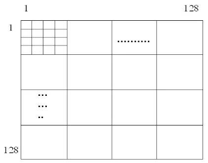
The study of Hasan & Nur [9] attempted to find a way out in order to solve the problem. They suggested a simple approach where a 512×512 dimensional image should be divided into a number of 4×4 non overlapping blocks. Then the image should look like a 128×128 matrix where each entry is a 4×4 block as shown in Fig. 3. Each row of this 128×128 matrix should now be perpended with a 128-bit header that is initially reset. Whenever an overhead block is encountered in the row, the corresponding bit in the 128-bit header is set and the 11-bit block header is not considered for that block [9]. During decoding, the decoder simply looks for the set bits in
the 128-bit row header and don’t think over the 11-bits block header. For the reset bits, the decoder considers that there is an 11-bits block header. The improved encoding and decoding steps as given by Hasan & Nur [9] are given in the following subsections.
A. Encoding Steps
Step1: Prepend a 128 bit extra header in front of each
block-row, all bits are reset.
Step2: Take a m×n non-overlapping block of image as done in
focused algorithm (standard size of m and n is 4).
Step3: Find the difference of Min and Max value in selected
m×n block in X.
Step4: If Max-Min ≥ 128 i.e. overhead block, set the corresponding bit in 128 bit header. Keep no 11 bit block-header.
Step5: Subtract each pixel from Min value of a block and store
in separate Y bits of every pixel in new m×n block.in separate Y bits of every pixel in new m×n
block.
B. Decoding Steps
Step1: Read first 128 bits, find which are overhead blocks. Step2: Except the overhead blocks, take 11 bits block-header
and follow the decoding steps described in section III-A.
Although the improved technique suggested by Hasan & Nur [9] could reduce a good number of overhead bits from the focused algorithm, they introduced 128 overhead bits in essence for each row of 128×128 matrix. We investigated that, there is a good possibility that many a time the 128-bit row header suggested by Hasan & Nur [9] will contain all zeros when no block of that row suffers from overhead. Our statistical study in section VI shows that, in general, around 13.77% such rows of an image will contain no overhead blocks and therefore the 128-bit row header will simple be overhead bits.
Fig. 3 A 512×512 Image is Considered as 128×128 Matrix. Each Element is a 4×4 Block
V. SUGGESTED FURTHER IMPROVEMENT
Since we cannot exclude the advances suggested by Hasan & Nur [9] because of their effective way of reducing the original overhead bits introduced by our focused algorithm, we attempted to find out for how many cases their improvement is useless and suffers from 128-bits overhead for each row. We then incorporate the famous Run Length Encoding technique to further compress those 128-bits
headers. Our idea simply takes each 128-bits row header of the image encoded by the steps of section IV-A and then finds the run of each binary state. Our resulting first bit denotes the first binary state of the 128-bits row header, next 8 bits stand for how many bits are required to represent each run. If these 8 bits indicate 4 in decimal, next each 4-bits group will characterize a run. The following subsections introduce our improved encoding and decoding procedures.
A. Improved Encoding Steps
Step1: Prepend a 128-bits extra header in front of each
block-row, all bits are reset.
Step2: Take a m×n non-overlapping block of image as done in focused algorithm (standard size of m and n is 4).
Step3: Find the difference of Min and Max value in selected m×n block in X.
Step4: If Max-Min ≥ 128 i.e. overhead block, set the corresponding bit in 128-bits header. Keep no 11 bit block-header.
Step5: Subtract each pixel from Min value of a block and store
in separate Y bits of every pixel in new m×n block.
Step6: Make run length coding on the 128-bits header. The first
bit represent the initial binary state of the header, next 8 bits give the number n decided by the maximum possible bits required to represent each run, next each n bits group denote a run.
B. Improved Decoding Steps
Step1: Read the first bit of the stored bit-stream. Step2: Read next 8 bits and find n.
Step3: Find the runs each by decoding n-bits group. Step4: Now follow the decoding procedure of section IV-B
VI.PERFORMANCE STUDIES
We studied 200 standard textbook images and 1000 randomly selected images for finding out how many times the 128-bits row header contains either all ones or all zeros. 13.77 % cases were come across for which the 128-bits row header contain either all ones or all zeros. Irrespective of the contents of the row headers, we applied Run Length Coding on the row headers and therefore achieved 4.97% better compression ratio on average for gray-scale images and 3.11% better compression ratio for color images. Table 1 shows the number of overhead bits reduced for some well-known test images. Table 2 shows a comparative compression ratio analysis for the same images. Table 3 shows a portion of our statistical analysis to find out the cases where the 128-bits row header will contain all zeros or all ones.
Again, in order to prove that the suggested improvement losses no bit, we calculated its ∆PSNR as defined by equation 1. The ∆PSNR calculation is shown in table 4.
∆PSNR=PSNR -PSNR (1)
TABLEI
OVERHEAD BIT REDUCTION BY PROPOSED IMPROVEMENT
Test Image Overhead Bits by
Focused Algorithm Improvement of Hasan & Overhead Bits by Nur [9]
Overhead Bit Reduction by
Hasan & Nur [9] Overhead Bit Reduction by Proposed Improvement
Baboon 21186 16384 4802 3345
Lena 36509 16384 20125 16229
Cameraman 72578 16384 56194 49397
Iris 25060 16384 8676 8102
TABLEII
COMPARATIVE COMPRESSION RATIO ANALYSIS
Test Image Compression Ratio by Focused Algorithm
Compression Ratio by Hasan & Nur [9]
Compression Ratio by
Proposed Improvement
Compression Ratio Gained
Baboon 28.10 31.21 31.73 0.52
Lena 35.66 38.98 40.27 1.29
Cameraman 39.18 41.03 44.54 3.51
Iris 27.62 29.88 31.00 1.12
TABLEIII
PORTION OF STUDY TO FIND ALL 1’S OR ALL 0’S IN 128-BITS ROW
HEADER
Test Image Number of All Zero/ All One Row Header
VII. CONCLUSIONS
In this paper, we investigated a novel spatial domain lossless image compression method and its existing improvement. The overhead introduced by the focused algorithm is properly analyzed along with the careful overhead studies of the existing improvement. We then suggested a straight forward approach in order to further compress this current stream of studies. The statistical evidence shown in our study has proved that the proposed modification is capable of achieving higher compression ratio as compared to the focused algorithm and its improvement. Moreover, our proposed improvement did not loss any bit during the compression-decompression process.
REFERENCES
[1] K. Sayood, Introduction to Data Compression, 2nd ed. Moorgan Kaufmann, 1991.
[2] R. Steinmetz, K. Nahrstedt, Multimedia: Computing, Communications and Applications, 1st Ed., Pearson Education Inc, ISBN: 81-7808-319-1, 2005.
[3] R.C. Gonzalez, R.E. Woods, Digital Image Processing, 2nd Ed., Pearson Prentice Hall, ISBN: 81-7758-168-6, 2005.
[4] T. Acharya, A.K. Ray, Digital Image Processing: Principles and Applications, John Wiley & Sons Inc., ISBN: 10 0-471-71998-6, 2005.
[5] M. Nelson, J.L. Gailly, The Data Compression Book, 2nd ed. New York: M & T Books, 1996.
[6] M. Hasan, K.M. Nur, A Lossless Image Compression Technique using Location Based Approach, International Journal of Scientific and Technology Research, Vol-1, Issue-2, 2012.
[7] G.K. Wallace, The JPEG Still Picture Compression Standard, IEEE Transactions on Consumer Electronics, 1991.
[8] W.B. Pennebaker, J.L. Mitchell, JPEG Still Image Data Compression Standard, Van Nostrand Reinhold, 1993.
[9] M. Hasan and K.M. Nur, An Improved Approach for Spatial Domain Lossless Image Data Compression Method by Reducing Overhead Bits”, International Journal of Scientific and Engineering Research, vol. 3, issue 4, 2012.
[10] S.A. Hassan and M. Hussain, Spatial Domain Lossless Image Data Compression Method, International Conference of Information and Communication Technologies, 2011.
[11] J.Y. Liang, C.Sheng Chen, C.H. Huang, and L. Liu, Lossless Compression of Medical Images using Hilbert space-filling Curves, Computerized Medical Imaging and Graphics-32, pp. 174-182, 2008. [12] L. Zhang, B. Hu, Y. Li, and W. Yu, An Algorithm for Moving
Multi-target Prediction in a Celestial Background, Communications in Computer and Information Science (CCIS) 61, pp 41-47, 2009.
[13] S.K. Pattanik, K.K. Mahapatra, and G. Panda, A Novel Lossless Image Compression Algorithm using Arithmetic Modulo Operation, IEEE International Conference on Cybernetics & Intelligence Systems (CIS) and Robotics Automation & Mechatronics (RAM) (CIS-RAM 2006), Thailand, pp. 234-238, 2006.
[14] K. Ramteke and S. Rawat, Lossless Image Compression LOCO-R Algorithm for 16 bit Image, 2nd National Conference on Information and Communication Technology (NCICT), pp. 11-14, 2011.
[15] M.S. Al-Wahaib and K. Wong, A Lossless Image Compression Algorithm Using Duplication Run Length Coding, IEEE Conference on Network Application Protocols and Services, pp. 245-250, 2010.
[16] C. Saravanan and R. Ponalagusamy, Lossless Grey-Scale Image Compression Using Source Symbol Reduction and Huffman Coding, International Journal of Image Processing, IJIP, vol-3, issue-5, pp. 246-251, 2009.
[17] O. Kubasova and P. Toivanen, Lossless Compression Methods for Hyperspectral Images, International Conference on Pattern Reognition (ICPR), 2004.
[18] S.C. Huang, L.G. Chen, and H.C. Chang, A Novel Image Compression Algorithm by Using LOG-EXP Transform, International Symposium on Circuits and Systems, ISCAS(4), pp. 17-20, 1999, DOI: ISCAS.1999.779932. [19] J. Ziv and A. Lempel, A Universal Algorithm for Sequential Data
Compression, IEEE Transaction on Information Theory (23-3), pp. 337-343, 1977.
[20] K. Belloulata, R. Stasinski, and J. Konrad, Region-based Image Compression Using Fractals and Shape-adaptive DCT, International Conference on Image Processing, pp. 815-819, 1999.
[21] K. Belloulata and J. Konrad, Fractal Image Compression with Region-Based Functionality, IEEE Transaction on Image Processing, vol. 11, no. 4, 2002.
[22] H. Hartenstein, M. Ruhl, and D. Saupe, Region-Based Fractal Image Compression, IEEE Transaction on Image Processing, vol. 9, no. 7, 2000.
TABLEIV ∆PSNRCALCULATION
Test Image ∆PSNR