Western University Western University
Scholarship@Western
Scholarship@Western
Electronic Thesis and Dissertation Repository
6-20-2018 11:00 AM
Constant Envelope DCT- and FFT- based Multicarrier Systems
Constant Envelope DCT- and FFT- based Multicarrier Systems
Rayan Alsisi
The University of Western Ontario Supervisor
Dr. Raveendra Rao
The University of Western Ontario
Graduate Program in Electrical and Computer Engineering
A thesis submitted in partial fulfillment of the requirements for the degree in Doctor of Philosophy
© Rayan Alsisi 2018
Follow this and additional works at: https://ir.lib.uwo.ca/etd
Part of the Systems and Communications Commons
Recommended Citation Recommended Citation
Alsisi, Rayan, "Constant Envelope DCT- and FFT- based Multicarrier Systems" (2018). Electronic Thesis and Dissertation Repository. 5473.
https://ir.lib.uwo.ca/etd/5473
Abstract
Discrete Cosine Transform (DCT)- and Fast Fourier Transform (FFT)- based Orthogonal Frequency Division Multiplexing (OFDM) systems with a variety of angle modulations are considered for data transmission. These modulations are used with the purpose of achieving Constant Envelope (CE) transmitted signals, for superior power efficiency with nonlinear High Power Amplifier (HPA), typically used at the transmitter in OFDM sys-tems. Specifically, four angle modulations are considered: i) Phase Modulation (PM); ii) Frequency Modulation (FM); iii) Continuous Phase Modulation (CPM); and iv) Contin-uous Phase Chirp Modulation (CPCM). Descriptions of DCT- and FFT- based OFDM systems with M-ary Pulse Amplitude Modulation (MPAM) mapper, with these modula-tions, are given and expressions for transmitted signals are developed. The detection of these signals in Additive White Gaussian Noise (AWGN) and multipath fading channels is addressed. The receiver structure consists of arctangent demodulator followed by the optimum OFDM receiver for memoryless PM and FM modulations. However, for CPM and CPCM modulations that have inherent memory, arctangent demodulator followed by correction with oversampling technique is used prior to the optimum OFDM receiver. Closed-form expressions for Bit Error Rate (BER) have been derived and are function of: i) Signal-to-Noise Ratio, (Eb/N0); ii) Modulation parameters; iii) Number of amplitude
levels of M-PAM mapper; and iv) parameters of multipath fading environment.
Acknowledgements
All praise and thanks to Allah, the most gracious most merciful, for bestowing upon me His countless bounties, and strength and patience to complete my doctoral study. Without His guidance and blessings, nothing is possible.
I owe much gratitude and deep appreciation to my supervisor Prof. Raveendra K. Rao for giving me this unique opportunity to work in his group and learn from his vast knowledge and experience. His time is always available for discussion, encouragement, insightful guidance, consistent support, invaluable advice, and constructive criticism. Undoubtedly without his dedication my Ph.D thesis would not have taken this shape.
Acknowledgements are due to Islamic University of Madinah for granting and pro-viding scholarship and financial support through Saudi Cultural Bureau in Canada to completing my PhD program at the University of Western Ontario
I would like to express my deepest gratitude to my parents, brothers, and sister for their encouragement and support over the years. The role of parents in my upbringing and their prayers have played a major part in what I am today. I wish that I can compensate them for their love and support all the past years. I would also like to show my sincere gratitude to my wife and my children for being beside me during the PhD journey.
Dedication
Table of Contents
Abstract . . . i
Acknowledgements . . . iii
Dedication . . . iv
List of Tables . . . viii
List of Figures . . . x
List of Abbreviations . . . xvi
1 Introduction to Thesis . . . 1
1.1 Introduction . . . 1
1.2 Basics of OFDM . . . 5
1.3 Peak-to-Average Power Ratio (PAPR) in an OFDM System . . . 9
1.4 Constant Envelope Signals and Systems . . . 15
1.5 Literature Survey and Motivation . . . 16
1.6 Thesis Objectives . . . 22
1.7 Thesis Organization . . . 23
1.8 Conclusions . . . 24
2 Generic FFT- and DCT-OFDM System . . . 25
2.1 Introduction . . . 25
2.2 Baseband OFDM System . . . 25
2.2.1 FFT-OFDM Signal . . . 28
2.2.2 DCT-OFDM Signal . . . 29
2.3 Guard Interval/Cyclic Prefix . . . 30
2.3.1 FFT-OFDM System . . . 30
2.3.2 DCT-OFDM System . . . 34
2.4 PAPR of OFDM Signals . . . 37
2.4.1 PAPR Statistics . . . 37
2.4.2 Models of HPA and their effects . . . 40
3 Constant Envelope DCT- and FFT-OFDM Systems with PM . . . . 46
3.1 Introduction . . . 46
3.2 Signals in DCT- and FFT-OFDM Systems with PM . . . 47
3.3 CE-OFDM Transmitter . . . 47
3.4 CE-OFDM Receiver: Signal Detection and Performance . . . 50
3.4.1 Phase Demodulator . . . 51
3.4.2 OFDM Demodulator . . . 53
3.4.3 BER Probability of CE-OFDM system . . . 55
3.5 Performance of CE-OFDM system over Fading Channels . . . 57
3.5.1 Frequency Non-Selective Fading Channel . . . 57
3.5.2 BER performance of CE-OFDM system . . . 58
3.5.3 Rayleigh Fading Channel . . . 59
3.5.4 Rician Fading Channel . . . 61
3.6 Numerical Results and Discussion . . . 62
3.6.1 Performance in AWGN Channel . . . 62
3.6.2 Performance over Fading Channels . . . 66
3.7 CE-DCT- and DCT-OFDM Systems with TWTA Amplifier . . . 73
3.8 Conclusions . . . 76
4 Constant Envelope DCT- and FFT-OFDM Systems with FM4,5 . . . 77
4.1 Introduction . . . 77
4.2 DCT- and FFT-OFDM Signals with FM . . . 78
4.3 CE-OFDM Transmitter . . . 78
4.4 CE-OFDM Receiver: Signal Detection and Performance . . . 79
4.4.1 FM Demodulation . . . 80
4.4.2 OFDM Demodulator . . . 82
4.5 Performance of CE-OFDM System over Fading Channels . . . 84
4.6 Numerical Results and Discussion . . . 86
4.6.1 Performance in AWGN Channel . . . 86
4.6.2 Performance in Fading Channels . . . 93
4.6.3 Effect of TWTA Amplifier on System Performance . . . 97
4.6.4 Comparison of PM and FM with DCT- and FFT-OFDM . . . . 99
5 Constant Envelope DCT- and FFT-OFDM Systems with CPM6 . . . 102
5.1 Introduction . . . 102
5.2 Signals in DCT- and FFT-OFDM Systems with CPM . . . 103
5.3 OFDM System with CPM: Transmitter . . . 105
5.4 OFDM System with CPM: Receiver . . . 107
5.4.1 Phase Demodulation and OFDM Demodulator . . . 108
5.4.2 BER Probability of OFDM system with CPM . . . 109
5.5 Performance over Fading Channels . . . 111
5.6 Numerical Results and Discussion . . . 112
5.6.1 Performance in AWGN Channel . . . 112
5.6.2 Performance over Fading Channels . . . 115
5.7 CE-DCT- and DCT-OFDM Systems with TWTA Amplifier . . . 123
5.7.1 Comparison of BER of OFDM System with FM, PM and CPM . 125 5.8 Conclusion . . . 127
6 Constant Envelope DCT- and FFT-OFDM Systems with CPCM7 . . 128
6.1 Introduction . . . 128
6.2 Signals in DCT- and FFT-OFDM Systems with CPCM . . . 129
6.3 OFDM System with CPCM: Transmitter . . . 130
6.4 OFDM Sytem with CPCM: Receiver . . . 132
6.4.1 Analysis over AWGN Channel . . . 132
6.5 Performance over Fading Channels . . . 135
6.6 Numerical Results and Discussion . . . 136
6.6.1 Performance over AWGN Channel . . . 136
6.6.2 Performance over Fading Channels . . . 140
6.6.3 Effect of TWTA Amplifier on System Performance . . . 147
6.6.4 Comparison of DCT- and FFT-OFDM system with FM, CPM, and CPCM . . . 148
6.7 Conclusion . . . 150
7 Conclusions . . . 151
7.1 Introduction . . . 151
7.2 Summary of Contributions . . . 151
7.3 Suggestion for Further Research . . . 154
List of Tables
Section Page
3.1 Comparison of CE-DCT- and CE-FFT-OFDM systems (2-PAM mapper) atPb = 10−5 as a function ofhp . . . 62
3.2 Comparison of CE-DCT- and CE-FFT-OFDM systems (4-PAM mapper) atPb = 10−5 as a function ofhp . . . 63
3.3 Comparison of CE-DCT- and CE-FFT-OFDM systems (8-PAM mapper) atPb = 10−5 as a founction ofhp . . . 65
3.4 Comparison of probability of bit error performances of CE-DCT-OFDM system over AWGN, Rician and Rayleigh channels. . . 72 3.5 Comparison of probability of bit error performances of CE-FFT-OFDM
system over AWGN, Rician and Rayleigh channels. . . 72 4.1 Comparison of CE-DCT- and CE-FFT-OFDM systems (2-PAM mapper)
atPb = 10−5 as a function ofhf . . . 87 4.2 Comparison of CE-DCT- and CE-FFT-OFDM systems (4-PAM mapper)
atPb = 10−5 as a function ofhf . . . 88 4.3 Comparison of CE-DCT- and CE-FFT-OFDM systems (8-PAM mapper)
atPb = 10−5 as a founction ofhf . . . 89 4.4 Comparison of probability of bit error performances of CE-DCT-OFDM
system (M = 2, hf = 0.7) over AWGN, Rician (K = 6 dB) and Rayleigh channels . . . 96 4.5 Comparison of probability of bit error performances of CE-FFT-OFDM
system (M = 2, hf = 0.7) over AWGN, Rician (K = 6 dB) and Rayleigh channels . . . 96 5.1 Comparison of CE-DCT- and CE-FFT-OFDM systems (2-PAM mapper)
atPb = 10−5 as a function ofh . . . 113 5.2 Comparison of CE-DCT- and CE-FFT-OFDM systems (4-PAM mapper)
atPb = 10−5 as a function ofh . . . 114 5.3 Comparison of CE-DCT- and CE-FFT-OFDM systems (8-PAM mapper)
atPb = 10−5 as a function ofh . . . 115 5.4 Comparison of probability of bit error performances of CE-DCT-OFDM
system over AWGN, Rician and Rayleigh channels. . . 121 5.5 Comparison of probability of bit error performances of CE-FFT-OFDM
system over AWGN, Rician and Rayleigh channels. . . 121 6.1 Comparison of CE-DCT- and CE-FFT-OFDM systems (2-PAM mapper)
List of Tables
6.2 Comparison of CE-DCT- and CE-FFT-OFDM systems (4-PAM mapper) atPb = 10−5 as a function of (h, 0.15) . . . 138 6.3 Comparison of CE-DCT- and CE-FFT-OFDM systems (8-PAM mapper)
atPb = 10−5 as a function of (h, 0.15) . . . 139 6.4 Comparison of CE-DCT- and CE-FFT-OFDM systems (2-PAM mapper)
atPb = 10−5 as a function of (1, w) . . . 140 6.5 Comparison of CE-DCT- and CE-FFT-OFDM systems (4-PAM mapper)
atPb = 10−5 as a function of (1, w) . . . 141 6.6 Comparison of CE-DCT- and CE-FFT-OFDM systems (8-PAM mapper)
atPb = 10−5 as a function of (1, w) . . . 142 6.7 Comparison of CE-DCT-OFDM system (M = 2,(0.9,0.15)) over AWGN,
Rician (K = 6 dB) and Rayleigh channels . . . 142 6.8 Comparison of CE-FFT-OFDM system (M = 2,(0.9,0.15)) over AWGN,
Rician (K = 6 dB) and Rayleigh channels . . . 147 7.1 Eb/N0 required atPb = 10−5 for various modulations in an OFDM system
(2-PAM mapper). . . 152 7.2 Power penalty required for various modulations in an OFDM system
(2-PAM mapper) over fading channels at Pb = 10−5. . . 153 7.3 Expressions for bandwidth of transmitted signal in CE-OFDM system for
List of Figures
Section Page
1.1 Representation of a three-path wireless channel. . . 2
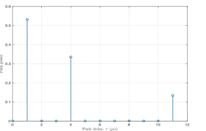
1.2 Power vs. delay profile for a three-path wireless channel. . . 2
1.3 Transfer function of a three-path wireless channel. . . 3
1.4 Spectrum of FFT-based OFDM signal withN = 8 and X(n) = +1 for alln. 7 1.5 Spectrum of DCT-based OFDM signal withN = 8 andX(n) = +1 for all n. . . 8
1.6 Block diagram for generation of OFDM signal. . . 8
1.7 DCT-OFDM signal as a function of time. . . 11
1.8 Real and imaginary parts of FFT-OFDM as a function of time . . . 12
1.9 Instantaneous power of DCT-OFDM signal. . . 13
1.10 Instantaneous power of FFT-OFDM signal. . . 13
1.11 Transfer characteristics of typical HPA. . . 14
1.12 Block diagram of CE-OFDM system. . . 17
1.13 Instantaneous powers of signals in DCT-OFDM and CE-DCT-OFDM sys-tems. . . 17
2.1 The generic block diagram of DCT- and FFT-OFDM baseband transceiver system. . . 26
2.2 Signal space diagrams for (a) 2-PAM and (b) 4-PAM mappers. . . 27
2.3 Discrete time signal at the output for MPAM mapper. . . 27
2.4 OFDM symbol with CP . . . 31
2.5 Structure of OFDM demodulator using a bank ofN correlators . . . 32
2.6 OFDM symbol with symmetric extension. . . 34
2.7 Symmetries for (a)x(k) and (b) h(k) to convert linear convolution into a symmetric convolution. . . 36
2.8 CCDF of PAPR of an OFDM signal for N = 32,64,128,256,512, and 1024. 39 2.9 CCDFs of PAPR of DCT- and FFT-OFDM signals forN = 32. . . 39
2.10 AM/AM functions for SSPA (for p= 3,10) and TWTA for Asat = 2. . . 42
2.11 AM/PM function for TWTA for αφ =π/12 andβφ = 0.25. . . 42
2.12 BER performance of DCT-OFDM (8-PSK, N = 64) system with SSPA for various values of IBO. . . 43
2.13 BER performance of DCT-OFDM (8-PSK, N = 64) system with TWTA for various values of IBO. . . 44
2.14 Efficiency (ηA) of Class A HPA as a function of IBO. . . 44
3.1 Transmitter and receiver structures for CE-OFDM system with PM . . . 48
List of Tables
3.4 Structure of OFDM demodulator . . . 54 3.5 Signal constellation of MPAM demapper . . . 55 3.6 Probability density function of Rayleigh random variable as a function ofσ. 59 3.7 Probability density function for Rice random variable forσ= 1 and various
values of a. . . 60 3.8 Probability of bit error performances of CE-DCT- and CE-FFT-OFDM
systems for (2-PAM mapper) over AWGN channel. . . 63 3.9 Probability of bit error performances of CE-DCT- and CE-FFT-OFDM
systems for (4-PAM mapper) over AWGN channel. . . 64 3.10 Probability of bit error performances of CE-DCT- and CE-FFT-OFDM
systems for (8-PAM mapper) over AWGN channel. . . 64 3.11 Probability of bit error performance of CE-DCT-OFDM system as a
func-tion of M forhp = 0.6 over AWGN channel. . . 65
3.12 Probability of bit error performance of CE-FFT-OFDM system as a func-tion of M forh= 0.6 over AWGN channel. . . 66 3.13 Probability of bit error performance of CE-DCT-OFDM system as a
func-tion of hp and M over AWGN channel. . . 67
3.14 Probability of bit error performance of CE-FFT-OFDM system as a func-tion of hp and M over AWGN channel. . . 67
3.15 Comparison of analytical and simulation results for CE-DCT-OFDM sys-tem (4-PAM mapper) over AWGN channel. . . 68 3.16 Comparison of analytical and simulation results for CE-DCT-OFDM
sys-tem (8-PAM mapper) over AWGN channel. . . 68 3.17 Probability of bit error performances of CE-DCT- and CE-FFT-OFDM
systems (2-PAM mapper) over Rayleigh fading channel. . . 69 3.18 Probability of bit error performances of CE-DCT- and CE-FFT-OFDM
systems (4-PAM mapper) over Rayleigh fading channel. . . 69 3.19 Probability of bit error performances of CE-DCT- and CE-FFT-OFDM
systems (8-PAM mapper) over Rayleigh fading channel. . . 70 3.20 Probability of bit error performances of CE-DCT- and CE-FFT-OFDM
systems (2-PAM mapper) over Rician fading channel (K = 6 dB). . . 71 3.21 Probability of bit error performances of CE-DCT- and CE-FFT-OFDM
systems (4-PAM mapper) over Rician fading channel (K = 6 dB). . . 71 3.22 Probability of bit error performances of CE-DCT- and CE-FFT-OFDM
systems (8-PAM mapper) over Rician fading channel (K = 6 dB). . . 72 3.23 Comparison of probability of bit error performances of CE-DCT-OFDM
system (2-PAM mapper, hp = 1) over AWGN, Rician (K = 6 dB) and
Rayleigh channels. . . 73 3.24 Comparison of probability of bit error performances of CE-FFT-OFDM
system (2-PAM mapper, hp = 1) over AWGN, Rician (K = 6 dB) and
Rayleigh channels as a function of SNR. . . 74 3.25 Probability of bit error performances of CE-DCT- and CE-FFT-OFDM
systems (4-PAM mapper, hp = 0.5)as function of Rice factor for Rician
List of Tables
3.26 Probability of bit error performances of CE-DCT-OFDM and performance of DCT-OFDM systems as a function of IBO for TWTA. . . 75 4.1 Transmitter and receiver structures for DCT- and FFT-OFDM systems
with FM . . . 80 4.2 Probability of bit error performances of CE-DCT- and CE-FFT-OFDM
systems (2-PAM mapper) over AWGN channel. . . 87 4.3 Probability of bit error performances of CE-DCT- and CE-FFT-OFDM
systems (4-PAM mapper) over AWGN channel. . . 88 4.4 Probability of bit error performances of CE-DCT- and CE-FFT-OFDM
systems (8-PAM mapper) over AWGN channel. . . 89 4.5 Probability of bit error performance of CE-DCT-OFDM system as a
func-tion of M forhf = 0.6 over AWGN channel. . . 90 4.6 Probability of bit error performance of CE-FFT-OFDM system as a
func-tion of M forhf = 0.6 over AWGN channel. . . 91 4.7 Probability of bit error performance of CE-DCT-OFDM system as a
func-tion of hf and M over AWGN channel. . . 91 4.8 Probability of bit error performance of CE-FFT-OFDM system as a
func-tion of hf and M over AWGN channel. . . 92 4.9 Comparison of analytical and simulation results of BER for
EC-DCT-OFDM system (4-PAM mapper) over AWGN channel. . . 92 4.10 Probability of bit error performances of CE-DCT- and CE-FFT-OFDM
systems (2-PAM mapper) over Rayleigh fading channel. . . 93 4.11 Probability of bit error performances of CE-DCT- and CE-FFT-OFDM
systems (4-PAM mapper) over Rayleigh fading channel. . . 94 4.12 Probability of bit error performances of CE-DCT- and CE-FFT-OFDM
systems (8-PAM mapper) over Rayleigh fading channel. . . 94 4.13 Probability of bit error performances of CE-DCT- and CE-FFT-OFDM
systems (2-PAM mapper) over Rician fading channel (K = 6 dB). . . 95 4.14 Probability of bit error performances of CE-DCT- and CE-FFT-OFDM
systems (4-PAM mapper) over Rician fading channel (K = 6 dB). . . 95 4.15 Probability of bit error performances of CE-DCT- and CE-FFT-OFDM
systems (8-PAM mapper) over Rician fading channel (K = 6 dB). . . 96 4.16 Comparison of probability of bit error performances of CE-DCT-OFDM
system (2−PAM mapper, hf = 0.7) over AWGN, Rician (K = 6 dB) and Rayleigh channels. . . 97 4.17 Comparison of probability of bit error performances of CE-FFT-OFDM
system (2−PAM mapper, hf = 0.7) over AWGN, Rician (K = 6 dB) and Rayleigh channels. . . 98 4.18 Probability of bit error performances of CE-DCT- and CE-FFT-OFDM
systems (4-PAM mapper,hf = 0.5) as a function of Rice factor for Rician Channel. . . 98 4.19 Probability of bit error performances of CE-DCT-OFDM and DCT-OFDM
List of Tables
4.20 Probability of bit error performances of DCT-OFDM system (4−PAM mapper) with PM (hp = 0.6) and FM (hf = 0.6) over AWGN, Rician
(K = 6 dB) and Rayleigh channels. . . 100 4.21 Probability of bit error performances of FFT-OFDM systems (4−PAM
mapper) with PM (hp = 0.6) and FM (hf = 0.6) over AWGN, Rician
(K = 6 dB) and Rayleigh channels. . . 100 5.1 Rectangular frequency pulse shaping functionf(t) . . . 104 5.2 Phase function g(t) for rectangular frequency pulse function . . . 104 5.3 Phaseφ(t) in a CE-DCT-OFDM system (2-PAM mapper) with 8 subcarriers.105 5.4 Transmitter and receiver structures of OFDM system with CPM . . . 106 5.5 Probability of bit error performances of CE-DCT- and CE-FFT-OFDM
systems (2-PAM mapper) over AWGN channel. . . 113 5.6 Probability of bit error performances of CE-DCT- and CE-FFT-OFDM
systems (4-PAM mapper) over AWGN channel. . . 114 5.7 Probability of bit error performances of CE-DCT- and CE-FFT-OFDM
systems (8-PAM mapper) over AWGN channel. . . 115 5.8 Probability of bit error performance of CE-DCT-OFDM system as a
func-tion of M forh= 0.6 over AWGN channel. . . 116 5.9 Probability of bit error performance of CE-FFT-OFDM system as a
func-tion of M forh= 0.6 over AWGN channel. . . 116 5.10 Probability of bit error performance of CE-DCT-OFDM system as a
func-tion of h and M over AWGN channel. . . 117 5.11 Probability of bit error performance of and CE-FFT-OFDM system as a
function ofh and M over AWGN channel. . . 117 5.12 Comparison of analytical and simulation results for CE-DCT-OFDM
sys-tem (2-PAM mapper) over AWGN channel. . . 118 5.13 Comparison of analytical and simulation results for CE-DCT-OFDM
sys-tem (4-PAM mapper) over AWGN channel. . . 118 5.14 Probability of bit error performances of CE-DCT- and CE-FFT-OFDM
systems (2-PAM mapper) over Rayleigh fading channel. . . 119 5.15 Probability of bit error performances of CE-DCT- and CE-FFT-OFDM
systems (4-PAM mapper) over Rayleigh fading channel. . . 120 5.16 Probability of bit error performances of CE-DCT- and CE-FFT-OFDM
systems (8-PAM mapper) over Rayleigh fading channel. . . 120 5.17 Probability of bit error performances of CE-DCT- and CE-FFT-OFDM
systems (2-PAM mapper) over Rician fading channel (K = 6 dB). . . 121 5.18 Probability of bit error performances of CE-DCT- and CE-FFT-OFDM
systems (4-PAM mapper) over Rician fading channel (K = 6 dB). . . 122 5.19 Probability of bit error performances of CE-DCT- and CE-FFT-OFDM
systems (8-PAM mapper) over Rician fading channel (K = 6 dB). . . 122 5.20 Comparison of probability of bit error performances of CE-DCT-OFDM
List of Tables
5.21 Comparison of probability of bit error performances of CE-FFT-OFDM system (2-PAM mapper, h = 0.7) over AWGN, Rician (K = 6 dB) and Rayleigh channels. . . 124 5.22 Probability of bit error performances of CE-DCT- and CE-FFT-OFDM
systems as function of Rice factor. . . 124 5.23 Probability of bit error performances of CE-DCT- and of DCT-OFDM
systems as a function of IBO for TWTA model. . . 125 5.24 Comparison of probability of bit error performancess of DCT-OFDM
sys-tem (4−PAM) with PM (hp = 0.6), FM (hf = 0.6) and CPM (h = 0.6)
over AWGN, Rician (K = 6 dB) and Rayleigh channels. . . 126 5.25 Comparison of probability of bit error performancess of FFT-OFDM
sys-tem (4−PAM) with PM (hp = 0.6), FM (hf = 0.6) and CPM (h = 0.6)
over AWGN, Rician (K = 6 dB) and Rayleigh channels. . . 126 6.1 Phase and frequency as a function of time forx(k) =±1 . . . 130 6.2 Block diagram of CE-OFDM system with CPCM . . . 131 6.3 Probability of bit error performances of CE-DCT- and CE-FFT-OFDM
systems (2-PAM mapper) as a function of (h,0.15) over AWGN channel. 136 6.4 Probability of bit error performances of CE-DCT- and CE-FFT-OFDM
systems (4-PAM mapper) as a function of (h,0.15) over AWGN channel. 137 6.5 Probability of bit error performances of CE-DCT- and CE-FFT-OFDM
systems (8-PAM mapper) as a function of (h,0.15) over AWGN channel. 138 6.6 Probability of bit error performances of CE-DCT- and CE-FFT-OFDM
systems (2-PAM mapper) as a function of (1, w) over AWGN channel. . . 139 6.7 Probability of bit error performances of CE-DCT- and CE-FFT-OFDM
systems (4-PAM mapper) as a function of (1, w) over AWGN channel. . . 140 6.8 Probability of bit error performances of CE-DCT- and CE-FFT-OFDM
systems (8-PAM mapper) as a function of (1, w) over AWGN channel. . . 141 6.9 Comparison of analytical and simulation results of BER for
CE-DCT-OFDM system (4-PAM mapper) over AWGN channel. . . 142 6.10 Probability of bit error performances of CE-DCT- and CE-FFT-OFDM
systems (2-PAM mapper) over Rayleigh fading channel. . . 143 6.11 Probability of bit error performances of CE-DCT- and CE-FFT-OFDM
systems (4-PAM mapper) over Rayleigh fading channel. . . 143 6.12 Probability of bit error performances of CE-DCT- and CE-FFT-OFDM
systems (8-PAM mapper) over Rayleigh fading channel. . . 144 6.13 Probability of bit error performances of CE-DCT- and CE-FFT-OFDM
systems (2-PAM mapper) over Rician fading channel (K = 6 dB). . . 144 6.14 Probability of bit error performances of CE-DCT- and CE-FFT-OFDM
systems (4-PAM mapper) over Rician fading channel (K = 6 dB). . . 145 6.15 Probability of bit error performances of CE-DCT- and CE-FFT-OFDM
systems (8-PAM mapper) over Rician fading channel (K = 6 dB). . . 145 6.16 Comparison of probability of bit error performances of CE-DCT-OFDM
6.17 Comparison of probability of bit error performances of CE-FFT-OFDM system (M = 2,(0.9,0.15)) over AWGN, Rician (K = 6 dB) and Rayleigh channels. . . 146 6.18 Probability of bit error performances of CE-DCT- and CE-FFT-OFDM
systems (4-PAM mapper, (0.9,0.2)) as a function of Rice factor. . . 147 6.19 Probability of bit error performances of CE-DCT-OFDM and DCT-OFDM
systems as a function of IBO for TWTA. . . 148 6.20 Probability of bit error performances of DCT-OFDM system (4−PAM
mapper) with CPCM (h = 0.8, w = 0.1), CPM (h = 0.6) and FM (hf = 0.6) over AWGN, Rician (K = 6 dB) and Rayleigh channels. . . 149 6.21 Probability of bit error performances of FFT-OFDM systems (4−PAM
mapper) with CPCM (h = 0.8, w = 0.1), CPM (h = 0.6) and FM (hf = 0.6) over AWGN, Rician (K = 6 dB) and Rayleigh channels. . . 150 7.1 Bandwidth as a function of modulation parameters (N = 64, T = 1) for
various angle modulation in an OFDM system. . . 155 7.2 Spectral efficiency as a function of modulation parameters (8PAM mapper,
List of Abbreviations
WLAN Wireless Local Area Network MCM Multicarrier Modulation
OFDM Orthogonal Frequency Division Multiplexing ISI Inter-Symbol Interference
ICI Inter-Carrier Interference FFT Fast Fourier Transform
IFFT Inverse Fast Fourier Transform DCT Discrete Cosine Transform
IDCT Inverse Discrete Cosine Transform PAPR Peak-to-Average-Power Ratio PM Phase Modulation
FM Frequency Modulation
CPM Continuous Phase Modulation CPCM Continuous Phase Chirp Modulation CE Constant Envelope
PAM Pulse Amplitude Modulation
MPAM M-ary Pulse Amplitude Modulation CFO Carrier Frequency Offset
PSK Phase Shift Keying
QAM Quadrature Amplitude Modulation
MQAM M-ary Quadrature Amplitude Modulation JPEG Joint Photographic Experts Group
MPEG Moving Picture Experts Group BPSK Binary Phase Shift Keying HPA High Power Amplifier ASK Amplitude Shift Keying PTS Partial Transmit Sequence LS Least Square
MMSE Minimum Mean Square Error SNR Signal-to-Noise Ratio
BER Bit Error Rate
AM Amplitude Modulation RMS Root Mean Square BPF Band Pass Filter LPF Low Pass Filter
PSD Power Spectral Density LOS Line of Sight
CSI Channel State Information AWGN Additive white Gaussian Noise ML Maximum Likelihood
D/A Digital-to-Analog Converter A/D Analog -to- Digital Converter
CCDF Complementary Cumulative Distribution Function ICT Information and Communication Technologies IEEE Institute of Electrical and Electronics Engineers i.i.d independent and identically distributed
Chapter 1
Introduction to Thesis
1.1
Introduction
Figure 1.1: Representation of a three-path wireless channel.
0 2 4 6 8 10 12
Path delay,τ (μs) 0
0.1 0.2 0.3 0.4 0.5 0.6
Pa
th
p
owe
r
0 100 200 300 400 500 600 700 800 900 1000 Frequency (kH z)
-25 -20 -15 -10 -5 0
20
log
10
|
H
(
f
)
|
,
(
dB
)
Figure 1.3: Transfer function of a three-path wireless channel.
In a single carrier system, the symbols are transmitted serially and the transmitted signal can be written as [4]:
x(t) = X
j
Xj q(t−(j−1)Ts) (1.1)
where Xj are data symbols obtained from an arbitrary modulation constellation, q(t) is the transmit pulse shape andTs is the data symbol duration. The received signal can be
written as [4]:
y(t) = x(t)∗h(τ;t) +n(t) =
∞ Z
−∞
h(τ;t)s(t−τ)dτ +n(t) (1.2)
where h(τ;t) is the response of the channel at time t due to an impulse applied at time (t−τ) and n(t) is the additive noise.
inter-symbol interference (ISI) is introduced. This is reflected in frequency domain, by the inverse relationship between bandwidth and delay spread. Since the delay spread are distinct, the frequency response of the channel, H(f), will exhibit power fluctuation as shown in Figure 1.3. Such fluctuation in the frequency domain will distort the received signal. Therefore, dispersion in the time domain leads to frequency-selectivity in the fre-quency domain. The coherence bandwidth of the channel, Bc, can be determined by the
reciprocal of maximum delay spread, τmax. That is, Bc = 1/τmax. If bandwidth of the
transmitted signal is greater than coherence bandwidth of the channel, the channel is said to be frequency-selective and the signal is severely distorted by the channel. However, if bandwidth of the transmitted signal is smaller than the coherence bandwidth of the channel, the channel is said to be frequency-nonselective [4]. For a single carrier system the coherence bandwidth of the channel is smaller than the modulation bandwidth and, therefore, the frequency selectivity effect of the channel cannot be ignored. For example consider a transmitted signal s(t) given by (1.1) over a 1 M Hz channel shown in Figure 1.2. The signal bandwidth is nearly equal 1/Ts Hz. Therefore, if s(t) with a bandwidth
of 1 M Hz,Ts = 1/(1×106) = 1µs, is transmitted over a channel withτmax= 11µs, ISI
spanns over, 11 symbols (τmax/Ts). Such severe ISI must be corrected at the receiver to
provide reliable communication. Thus, in a single-carrier system, equalization is essential to compensate for this ISI. There exists a number of techniques [5, 6, 7] for equalization and they require estimation of channel by transmitting training sequence known to the receiver. These estimation techniques vary in complexity, and accuracy [8, 9] and require long training times with added problems of convergence due to time-varying nature of the channel.
maintains the original transmission rate and the bandwidth of each subchannel is much less than the total bandwidth occupied by the signal and consequently has less coher-ence bandwidth of the channel which mitigates the ill effects of multipath fading to a large extent. In an MCM system, since several streams of data are transmitted simul-taneously, a fade occurring over the channel is spread out over many parallel symbols and each subcarrier experiences flat fading instead of frequency selective fading, thereby making equalization simple and of reasonable complexity [14, 15, 16]. Moreover, when a heavy fade occurs over a certain subcarrier, only part of the symbol under the affected subcarrier will be destroyed while others will not be affected.
Orthogonal Frequency Division Multiplexing (OFDM) is a subclass of Multicarrier Mod-ulation in which subcarriers in the system are chosen to be overlapping and orthogonal to each other. Such a system is highly bandwidth efficient due to overlapping spectra of adjacent subcarriers. The extraction of data over each individual subcarrier is still possible as long as the orthogonality condition is maintained. However, orthogonality among the subcarriers is destroyed due to ISI introduced over the multipath channel. To eliminate the ISI almost completely, a guard time is introduced for each transmitted OFDM block. The guard time is chosen larger than the expected maximum delay spread of the channel, τmax, to overcome the effects of ISI. Consider an OFDM system with
N number of subcarriers, then the symbol period is given by T = N Ts. If N = 250 is
chosen in the system, the symbol period is T =N T s = 250µs, which is nearly 23 times that ofτmax=11µs. Therefore, ISI can be eliminated by using a guard time greater than
τmax=11 µs in this example.
1.2
Basics of OFDM
using Fast Fourier Transform (FFT) technique for modulation of data symbols. However, such a system with FFT suffered from ISI problems. Another important contribution was due to Peled and Ruiz [20], who introduced the concept of cyclic prefix (CP) to overcome the problem of the ISI in an OFDM systems. OFDM has been adopted in several communications standards such as IEEE 802.11a/g/n [21, 22, 23], HIPERLAN/2 [24], IEEE 802.16a/d/e [25, 26] and IEEE 802.20 [27]. In all these standareds FFT-based OFDM system is used [28, 29, 30, 31]. More recently, there has been growing interest in DCT-based OFDM system due to its attractive properties [32]-[49].
OFDM signaling consists of a set of orthogonal subcarriers that are independently mod-ulated by data. The OFDM signal is the sum of these modmod-ulated subcarriers and it can be expressed as:
x(t) = X
j N−1
X
n=0
Xj(n)ϕn(t−(j−1)T), (j−1)T ≤t≤(j)T (1.3)
In (1.3),N is the number of OFDM subcarriers that are transmitted during thejth block. The data symbols obtained from an arbitrary modulation constellation, (Xj(0),· · · , Xj(N−1)), modulate theN OFDM subcarrier, (ϕ0(t),· · · , ϕN−1(t)),over thejth
signal-ing interval. T is the OFDM symbol period and the subcarriers meet the orthogonality condition. That is,
T Z
0
ϕn(t)ϕ∗k(t)dt =
1 n =k
0 otherwise
(1.4)
In an FFT-based OFDM system, complex exponential functions are used as orthogonal subcarriers and are given by:
ϕn(t) = r
1
Te
j2πfnt
,0≤t < T, n= 0,1,· · · , N−1 (1.5)
where the frequency of the nth subcarrier is fn = n/T Hz and the subcarrier spacing
required to achieve orthogonality is given by 1/T Hz.
and are given by:
ϕn(t) = r
2
Tcos(2πfnt),0≤t < T, n= 0,1,· · · , N−1 (1.6)
where the frequency of the nthsubcarrier is fn = n/2T Hz and the subcarrier spacing
required to achieve orthogonality is given by 1/2T Hz.
The spectra of FFT- and DCT-based OFDM signals are shown in Figure 1.4 and 1.5, respectively. It is noted that at the nth subcarrier frequency contributions due to all subcarriers except the nth subcarrier are zero. Also it is noted that subcarriers overlap and therefore the system is spectrally efficient.
A block diagram for generation of OFDM signal is shown in Figure 1.6. A high rate serial data stream is converted into many low-rate parallel data streams. These parallel data streams are then mapped to modulation symbols, for example using an MPAM mapper, which are then modulated onto the orthogonal subcarriers. The sum of the modulated subcarriers represents the transmitted OFDM signal.
-2 0 2 4 6 8 10
Normalized frequency, Hz
0 0.1 0.2 0.3 0.4 0.5 0.6 0.7 0.8 0.9 1
Sp
ectrum
m
agnitude,
|
X
(
f
))
|
-1 0 1 2 3 4 5
Normalized frequency, Hz
0 0.1 0.2 0.3 0.4 0.5 0.6 0.7 0.8 0.9 1
Sp
ectrum
m
agnitude,
|
X
(
f
))
|
Figure 1.5: Spectrum of DCT-based OFDM signal withN = 8 and X(n) = +1 for all n.
Figure 1.6: Block diagram for generation of OFDM signal.
system has better frequency-selective filter bank compared to that in an FFT-based system. As a result, the channel estimation and also the system performance can be improved in noisy environments [33, 37].
2. Using IDCT for modulation and DCT for demodulation in a DCT-based OFDM system results in better integrated system with reduced overall implementation cost [33, 37]. The DCT is widely adopted in image/video coding standards (e.g. JPEG, MPEG, H.261 [50, 51]).
3. The DCT uses real arithmetic compared to the complex arithmetic in FFT. This reduces the signal processing complexity and power consumption in the system, especially when an MPAM mapper is used [33, 37].
4. In the presence of frequency offset in an OFDM system, due to the energy-compaction property of DCT, the ICI coefficients in DCT-based OFDM system are concentrated around the main coefficient. As a result, the system is robust to Carrier Frequency Offset (CFO) [33, 44].
5. When modulation symbols are real-valued, the bandwidth of a DCT-based OFDM system is half the bandwidth of a corresponding FFT-based OFDM system [38]. The disadvantage of DCT-based OFDM system compared to an FFT-based OFDM sys-tem is the additional prefilter needed at the receiver to satisfy the symmetric channel impulse response constraint for short channels. For long channels, an FFT-OFDM sys-tem also requires a prefilter to shorten the channel [33, 37]. From now onwards DCT-and FFT-based OFDM systems would be referred to as DCT-OFDM DCT-and FFT-OFDM systems, respectively.
1.3
Peak-to-Average Power Ratio (PAPR) in an
OFDM System
(1.3), the FFT-OFDM signal can be written as:
xF F T(t) =
N−1
X
n=0
XF F T(n)ej2πnt/T,0≤t < T, (1.7)
where the scaled data symbols XF F T(n) are chosen from an M-point signal constella-tion such as MPSK, MQAM, or MPAM, N is the number of subcarriers and T is the duration of the OFDM symbol. It is noted that the suffix j in (1.3) has been dropped for convenience. The signal can be written as:
xF F T(t) =
N−1
X
n=0
{<[XF F T(n)] +j=[XF F T(n)]} ∗ {cos(2πnt/T) +jsin(2πnt/T)}
(1.8) The real and imaginary parts of xF F T(t) are:
<[xF F T(t)] =
N−1
X
n=0
<[XF F T(n)]cos(2πnt/T)− =[XF F T(n)]sin(2πnt/T) (1.9)
and
=[xF F T(t)] =
N−1
X
n=0
=[XF F T(n)]cos(2πnt/T) +<[XF F T(n)]sin(2πnt/T) (1.10)
Similarly using the basis functions in (1.6), the DCT-OFDM signal can be written as:
xDCT(t) =
N−1
X
0
XDCT(n)cos(πnt/T),0≤t ≤T (1.11)
The signal can be written as:
xDCT(t) =
N−1
X
n=0
{<[XDCT(n)] +j=[XDCT(n)]} ∗ {cos(πnt/T)} (1.12)
<[xDCT(t)] =
N−1
X
n=0
<[XDCT(n)]cos(πnt/T) (1.13)
and
=[xDCT(t)] =
N−1
X
n=0
=[XDCT(n)]cos(πnt/T) (1.14)
Figures 1.7 and 1.8 show plots of DCT-OFDM and FFT-OFDM signals, forN = 16 and
X(n)∈ {±1}(BPSK signal constellation), respectively. It is observed that the amplitude of OFDM signals fluctuates over an expansive range of values.
0 0.1 0.2 0.3 0.4 0.5 0.6 0.7 0.8 0.9 1 Normalized time, sec
-6 -4 -2 0 2 4 6
Signal
amplitude,
V
olts
DCT-OFDM signal
Figure 1.7: DCT-OFDM signal as a function of time.
The instantaneous signal powers of DCT-OFDM and FFT-OFDM signals are plotted in Figures 1.9 and 1.10, respectively. The ratio of the peak power and the average power of the signals in these figures are 10log10(4.058) = 6.1 dB and 10log10(4.279) = 6.3 dB,
0 0.1 0.2 0.3 0.4 0.5 0.6 0.7 0.8 0.9 1 Normalized time, sec
-10 -8 -6 -4 -2 0 2 4 6 8 10
Signal
amplitude,
V
olts
(FFT-OFDM signal) (FFT-OFDM signal)
Figure 1.8: Real and imaginary parts of FFT-OFDM as a function of time .
transmitter; otherwise the transmitted OFDM signal will be nonlinearly distorted which results in a loss of subcarrier orthogonality and hence turn degrades the performance of the system. The typical transfer characteristics of a HPA is shown in Figure 1.11 and consists of a linear region followed by a nonlinear region leading to the maximum output level. It is noted that the HPA has limited linear region, beyond which it saturates to the maximum output level. In the linear range the output power is equal to the input power multiplied by a gain factor, but as the input power increases beyond the linear range, the output power saturates.
0 0.1 0.2 0.3 0.4 0.5 0.6 0.7 0.8 0.9 1 Normalized time, sec
0 5 10 15 20 25 30 35
Instan
taneous
signal
p
ow
er,
W
atts
DCT-OFDM signal power Peak power
Average power
Figure 1.9: Instantaneous power of DCT-OFDM signal.
0 0.1 0.2 0.3 0.4 0.5 0.6 0.7 0.8 0.9 1 Normalized time, sec
0 10 20 30 40 50 60 70
Instan
taneous
signal
p
ow
er,
W
atts
FFT-OFDM signal power Peak power
Average power
Figure 1.11: Transfer characteristics of typical HPA.
the efficiency of a Class A high power amplifier is 0.5
106/10 × 100 = 12.3 % compared
1.4
Constant Envelope Signals and Systems
The general expression for Constant Envelope (CE) baseband signal can be written as:
s(t) =Ac ejφ(t) (1.15)
whereAc is the signal amplitude andφ(t) is the information carrying phase. The
instan-taneous and the average power of the signal in (1.15) are the same. Therefore, the PAPR of the signal is 0dB. The benefit of such a signal is that it does not require backoff. The HPA in the system can therefore be operated at the optimal saturation point thereby maximizing the average transmit power. This will in turn maximize the power efficiency of HPA. Constant envelope signals are highly attractive in systems where HPA is used. Therefore, it is important to embed digital information into the phaseφ(t) in (1.15). In the literature, constant envelope Continuous Phase Modulation (CPM) [54, 55] has been extensively examined for digital transmission using single carrier system. When multi-carrier OFDM signal is embedded in the phase φ(t), it is possible to obtain CE-OFDM signal. Such a signaling technique involves integration of multicarrier and constant en-velope techniques in a single system as shown in Figure 1.12. The high PAPR OFDM signal in the system is converted into a 0dB PAPR CE-OFDM signal. This permits HPA to operate near saturation level thus achieving maximum power efficiency. Figure 1.13 shows a comparison of instantaneous power of the DCT-OFDM and CE-DCT-OFDM signals.
In order to generate constant envelope signal given by (1.15), the modulating signal
φ(t) must be real-valued. In general , the modulating signal in an OFDM system is complex-valued. A real-valued modulating signal, however, can be obtained by tak-ing IFFT of a conjugate symmetric vector. For example, if the input data vector [XF F T(0),· · · , XF F T(N − 1)] of size 1 ×N is given, a conjugate symmetric vector [XF F T(0),· · · , XF F T(2N−1)] of size 1×2N can be obtained that satisfies the follow-ing conditions:
XF F T((N+n) =XF F T∗ (N −n), n = 1,2,· · · (1.16) and
The IFFT of this vector is given by:
xF F T(k) =
2N−1
X
n=0
XF F T(n)ej2πkn/2N, (1.18)
Using (1.16) and (1.17), (1.18) can be written as
xF F T(k) =
N−1
X
n=1
XF F T(N −n)ej2πk(N−n)/2N+
XF F T∗ (X(N −n))e−j2πk(N−n)/2N, k = 0,· · · ,2N−1 (1.19)
UsingB +B∗ = 2<[B], (1.19) can be written as:
= 2<
N−1
X
n=1
XF F T(n)ej2πkn/2N
(1.20)
Using the formula <[BC] =<[B]<[C]− =[B]=[C], (1.20) becomes
xF F T(k) = 2
N−1
X
n=1
<[XF F T(n)]cos(2πkn/2N)− =[XF F T(n)]sin(2πkn/2N) (1.21)
Thus, xF F T(k), k = 0,· · · ,2N − 1, is a real discrete-time signal. The equivalent continuous-time real-valued OFDM signal is given by:
xF F T(t) = 2
N−1
X
n=1
<[XF F T(n)]cos(2πnt/T)− =[XF F T(n)]sin(2πnt/T) (1.22)
In the case of DCT-OFDM system, the modulating signal generated by the system is always real for real input data vector.
1.5
Literature Survey and Motivation
Figure 1.12: Block diagram of CE-OFDM system.
0 0.1 0.2 0.3 0.4 0.5 0.6 0.7 0.8 0.9 1 Normalized time, sec
0 5 10 15 20 25 30 35
Instan
taneous
signal
p
ow
er,
W
atts
DCT-OFDM CE-DCT-OFDM
[39, 40, 41]. These studies show that the major advantage of using DCT in an OFDM system is that it can achieve better noise-immunity and hence can provide better BER performance than the conventional FFT-based OFDM system. Also, DCT-OFDM sys-tem can reduce the overall implementation cost.
In [42], it is noted that, particularly, for one-dimensional (1-D) mappers (real-valued formats), such as BPSK and MPAM, DCT-OFDM system can completely avoid the in-phase/quadrature-phase (IQ) imbalance problem, which is typically present in con-ventional FFT-OFDM system. In addition, it is possible to use fast DCT algorithm to achieve fewer computational steps in the system than using corresponding FFT al-gorithm. In [38], DCT is used to implement multicarrier modulation because of the bandwidth advantage it offers. A DCT-OFDM system is proposed in [43] using√M-ary Amplitude Shift Keying (ASK) mapper. A DCT-based implementation can also be em-ployed in an OFDM system with 2-D modulations (complex-valued formats) [44]. The performance analysis of DCT-OFDM system over a variety of multipath fading channels is considered in several recent works. By using a symmetrically extended data sequence, a DCT-OFDM system is examined in [45]. For the case of static and expo-nentially decaying channel profiles, with intersymbol interference (ISI), it is shown that the lower bound on throughput of DCT-OFDM system is greater than that of the DFT-OFDM system. The conditions on the impulse response of a frequency-selective channel for diagonalization using DCT into parallel, decoupled, and memoryless subchannels are derived in [36]. In [44], the performance of the DCT-OFDM system with a zero-padding guard interval scheme and an MMSE receiver over time-varying multipath Rayleigh fad-ing channel is investigated. The results show that employfad-ing a DCT-OFDM system rather than the conventional DFT-OFDM system can provide better bit error probabil-ity performance.
average power reduction compared to the conventional FFT-OFDM system [47]. In [48], several channel estimation methods for DCT-OFDM system are proposed such as Least Square (LS), Minimum Mean Square Error (MMSE), and Compressed Sensing estima-tors.
A major drawback of OFDM system is that the transmitted signal suffers from high values of PAPR which results in spectral broadening and intermodulation distortion par-ticularly when the signal is passed through a nonlinear HPA before transmission over the channel [61, 62]. Thus, a large amount of input power backoff is required which leads to reduced efficiency of HPA [54, 63]. There are several techniques to deal with the PAPR problem in an OFDM system such as coding, partial transmission sequences, clipping and filtering, selected mapping, tone reservation and interleaving etc [64, 65, 66, 67, 68, 69]. These techniques offer a variety of trade-offs in terms of complexity, performance and spectral efficiency. It is noted that these techniques do not completely eliminate the PAPR problem and may or may not require side information to be communicated to the receiver. Constant Envelope OFDM (CE-OFDM) designs can completely eliminate the problem of PAPR in an OFDM system. In such a system, angle modulation is used in place of I-Q modulation to create constant envelope transmitted signal with 0 dB PAPR. This permits HPA to operate near saturation level and thus achieving maximum power efficiency [70]. Due to this major advantage, CE-FFT-OFDM is being researched for ap-plications in wireless [70]-[91], optical [92, 93, 94], powerline [95, 96] and satellite [97, 98] communications as well as in radar systems [99, 100].
OFDM system with angle modulation is proposed in [71]. In such a system, orthogonal time functions are employed to transmit data by using “amplitude or frequency mod-ulation, or any other type of modulation suitable for the transmission of continuously varying time functions.”
for low frequency subcarriers than for high frequency subcarriers. In [74], the suitabil-ity of constant envelope multi-carrier modulation technique for the implementation of 1Gbps wireless link at 60 GHz is investigated. This technique combines OFDM and phase modulation to achieve: (i) constant envelope signal which allows HPA to operate near saturation level and thus maximizing power efficiency, and (ii) robust performance over multipath fading channel. When OFDM with PM is compared with OFDM with CPM, it is observed that the latter suffers from a 3 dB performance loss, when differ-ential demodulation is used. In [75], a constant envelope binary OFDM system with PM is presented and analyzed in AWGN channel. Approximate bandwidth requirements are predicted using the Carson’s rule and the root-mean square bandwidth for Gaussian angle modulated process. In the study of BER performance, a high carrier-to-noise ratio assumption (CN R > 10dB) is made in the analysis and ideal filters are used in the receiver frontend. Estimates are made on the transmitted data symbols by using IFFT demodulation at receiver. It is shown that the modulation index controls the spectral spreading and detection performance. In [76], the spectral properties of OFDM system with phase modulation are studied. It is shown that the fractional out-of-band power of transmitted signals can be better than conventional OFDM signals. Sub-optimum PM demodulator is analyzed for BER performance and compared to the optimum receiver. It is shown that the sub-optimum receiver performs close to the optimum for small mod-ulation index and at high SNRs.
In [77], a noncoherent CE-OFDM receiver is presented and analyzed. The matched-filter bank followed by the phase demodulator eliminates the effect of unknown phase shifts caused by the channel. The performance of this noncoherent receiver over Rayleigh and Ricean flat fading channels is also presented. It is shown that, for small modulation index and high SNR, simulation results are in good agreement with analytical approximations. In [78], a frequency-domain equalizer is proposed for CE-OFDM in multipath Rayleigh fading channel. It is shown that uncoded CE-OFDM, unlike uncoded OFDM, can exploit the frequency diversity of the channel. Compared to conventional OFDM system, CE-OFDM system is shown to offer gains in performance and in power amplifier efficiency. In [79], the influence of PM in CE-OFDM on ISI is analyzed and then a method is proposed to reduce ISI using zero-padding pattern in the transmitted OFDM symbol.
presented. The receiver allows for a simpler implementation without the need to compute the arctangent at the receiver. It is shown that the receiver performs well compared to the conventional arctangent based receiver for small and moderate modulation indices<0.7, for both AWGN and multipath fading channels. In [81], spectrally precoded OFDM and CE-OFDM systems are examined. The spectrally precoded OFDM signal provides very small power spectral sidelobes and the CE-OFDM signal exhibits 0dB PAPR. A specific CE-OFDM block signaling format is proposed to incorporate spectral precoding with an aim to suppress sidelobe power more effectively than in a conventional non-precoded CE-OFDM.
In [82], the performance of CE-OFDM system in multipath fading channels using FDE is studied. Several channel estimation techniques that use low-PAPR OFDM signals are examined in the presence of SSPA and TWTA amplifiers in the system. In [83], the ap-plication of convolutional coding to CE-OFDM is studied. A bound on the performance of convolutionally coded CE-OFDM is derived and illustrated. It is shown that chan-nel coding with interleaving provides good performance for low to moderate modulation indices. In [84], a threshold receiver for CE-OFDM is considered. It is noted that the receiver design depends on the modulation index used in the system. In [85, 86], the performance of OFDM system with FM for digital communication over Rayleigh-fading channel is examined. In such a system, OFDM baseband signal is used to modulate the frequency of the carrier signal. Expressions are derived for the BER for QAM-mapper in the system. Some techniques for improving the performance of such a system for data communication over a Rayleigh fading channel are suggested. In [87], CE-OFDM system that uses PM in AWGN and multipath channels is explored. A theoretical approach instead of Carson’s rule is used to analyze bandwidth of the system. It is shown that bandwidth requirement is determined by factors such as input data variance and mod-ulation index of PM. The results show that the system requires the same bandwidth as that of the conventional OFDM system for low values of modulation index.
In [38], a DCT-based multicarrier system with CPM is examined over fading channel for error probability performance using simulation. Results show that a larger modulation index, h, results in better performance. However, large value of h in such a system re-quires proper phase detection and correction.
well examined. However, DCT-based OFDM systems have not received much attention despite the fact that such systems have several attractive properties useful in communi-cation system. Thus, the motivation for this thesis is to investigate constant envelope OFDM signal designs for data communications. A wide range of angle modulations are considered for achieving constant envelope designs such as: i) PM; ii) FM; iii) CPM; and iv) CPCM. Both DCT- and FFT-based OFDM systems are examined. A generic system is used for examining these systems. A comprehensive study of these systems in terms of BER performance, bandwidth efficiency, complexity etc. is presented.
1.6
Thesis Objectives
There are four major objectives for this thesis. They are: 1. DCT- and FFT-OFDM Systems with PM
A system is presented to describe both DCT- and FFT-OFDM systems with PM. Expressions for bandwidth of signals in these systems are given. The detection of these signals in AWGN and fading channels (Rayleigh and Rician) is addressed and closed-form expression for BER of these systems are derived and illustrated as a function of SNR, modulation index, number of levels of MPAM mapper, and statistical parameters of noise environment. DCT-OFDM and FFT-OFDM systems with PM are compared in terms of BER, bandwidth, and structure of receivers. Also, the BER performances of DCT-OFDM system with PM and conventional DCT-OFDM system are compared as a function of IBO when TWTA amplifier is used in these systems.
2. DCT- and FFT-OFDM Systems with FM
3. DCT- and FFT-OFDM Systems with CPM
The concept of Continuous Phase Modulation (CPM) is introduced in DCT- and FFT-OFDM systems. A generic description of DCT- and FFT-OFDM systems with CPM is given and described. While these exist a wide class of CPM, in this thesis full-response CPM with rectangular pulse shaping is used. Detection of signals in these systems in AWGN and fading channels (Rayleigh and Rician) is addressed and a receiver structure that uses phase detector followed by phase correction with oversampling is suggested. Closed-form expressions for BER over AWGN and fading channels are derived and illustrated. The performances of DCT-OFDM system with CPM and conventional DCT-DCT-OFDM system are compared as a function of IBO when TWTA amplifier is used in these systems.
4. DCT- and FFT-OFDM Systems with CPCM
Chirp (Linear FM) modulation provides attractive wideband signals suitable for ap-plication in systems where interference rejection is important. In this thesis, DCT-and FFT-OFDM systems with CPCM are presented. The signals in these systems are described and their detection in AWGN and fading channels (Rayleigh and Ri-cian) is addressed and a receiver structure is suggested. Closed-form expressions for BER are derived and illustrated as a function chirp modulation parameters, SNR, number of levels of MPAM mapper and noise environment parameters. The influence of TWTA amplifier in DCT-OFDM system with CPCM and conventional DCT-OFDM system is examined as a function of IBO.
1.7
Thesis Organization
In Chapter 2, a generic description of FFT- and DCT-OFDM systems is given. The con-cept of guard interval/Cyclic prefix is mathematically explained in both continuous- and discrete-time. The PAPR statistics of FFT- and DCT-OFDM signals are presented. The models of HPA, both SSPA and TWTA, are described. The effect of IBO on efficiency of HPA is also illustrated.
these systems is illustrated.
In Chapter 4, DCT- and FFT-OFDM systems with FM are considered. The detection of signals in these systems in AWGN and fading channels is addressed. The BER per-formances of both systems are derived and illustrated. Also the effect of HPA on BER of these systems is examined.
In Chapter 5, DCT- and FFT-OFDM systems with CPM are presented and their prop-erties are studied. The detection performance of signals in these systems in AWGN and fading channels is examined. The effect of HPA on system bit error probability is also discussed.
In Chapter 6, CPCM is introduced in DCT- and FFT-OFDM systems. These systems are examined for their BER performances over AWGN and fading channels. The behaviour of these systems in the presence of HPA is illustrated.
In Chapter 7, the contributions of this thesis and the conclusions from the results ob-tained are summarized. Also, areas for further research in the light of the needs of modern communication systems are outlined.
1.8
Conclusions
Chapter 2
Generic FFT- and DCT-OFDM System
2.1
Introduction
In the previous Chapter some basic properties of OFDM system were identified. In this Chapter, the system is examined in more detail. A generic block diagram is presented to examine both DCT- and FFT-OFDM systems. The importance of cyclic prefix/guard in-terval in these systems is explained. The PAPR statistics of OFDM signals are presented and typical HPA models used in an OFDM system are examined.
2.2
Baseband OFDM System
A generic block diagram of a baseband OFDM system is shown in Figure 2.1 and can be used to study both FFT- and DCT-OFDM systems. The difference between these two systems is that, in the latter system IDCT/DCT are used for modulation/demodulation and in the former system IFFT/FFT are used for modulation/demodulation. The data source is assumed to be a sequence of binary digits [a0, a1, a2,· · ·] whereal, l = 0,1,· · ·
Figure 2.1: The generic block diagram of DCT- and FFT-OFDM baseband transceiver system.
adjacent signal amplitudes differ by one binary digit as illustrated in Figure 2.2 (b). This mapping is called Gray coding. By using this technique for the case of 4-PAM mapper, the mapper maps incoming symbols as given below:
00→ −3 01→ −1 11→ +1 10→ +3
(2.1)
The output of the signal mapper, in general, can be thought of as a discrete-time real signal as shown in Figure 2.3. The S/P converter enhances the duration of each symbol by a factor of N and converts serial data to parallel data. The output of this block can be written as a vector of N real numbers given by:
X = [X(0), X(1), X(2),· · · , X(N −1)] (2.2)
The discrete signal representing the data is fed to an N-point IFFT/IDCT block to obtain
Figure 2.2: Signal space diagrams for (a) 2-PAM and (b) 4-PAM mappers.
In order to differentiate samples in DCT- and FFT-OFDM systems, suffixes DCT and FFT are used, respectively
2.2.1
FFT-OFDM Signal
In this case, the relationship between (2.2) and (2.3) can be written as:
xF F T(k) =
N−1
X
n=0
XF F T(n)ej2πkn/N, k = 0,· · · , N −1, (2.4)
The parallel signal from the IFFT block is then converted to serial signal by using the P/S converter and then fed to D/A block to obtain
xF F T(t) =
N−1
X
n=0
XF F T(n)ej2πnt/T, 0≤t≤T (2.5)
where T is the OFDM symbol duration and n/T is the frequency of the nth subcarrier. For a 2-PAM mapper used in the system, T = N Tb, Tb is the duration of the data from the source. For a 4-PAM mapper T = N Ts, where Ts = KTb. It is noted that
[XF F T(0), XF F T(1),· · · , XF F T(N−1)] representes a block of N data symbols and the complex functions ej2πnt/T, n= 0,1,· · · , N −1 are referred to as the subcarriers of the system and are orthogonal to each other. It can be shown that the discrete sequence [xF F T(0), xF F T(1),· · · , xF F T(N −1)] can be obtained by sampling xF F T(t) at t = (kT)/N, k= 0,1, ,· · · , N −1. That is,
xF F T(k) = xF F T(t)|t=kT /N=
N−1
X
n=0
XF F T(n)ej2πkn/N, k = 0,· · · , N −1, (2.6)
and its frequency-domain representation is:
XF F T(n) = 1
N
N−1
X
k=0
It is noted that
1
N
N−1
X
k=0
ej2πpk/N e−j2πqk/N =
1 p=q
0 otherwise
(2.8)
2.2.2
DCT-OFDM Signal
The relationship between (2.2) and (2.3) can be written as:
xDCT(k) =
N−1
X
n=0
XDCT(n) cos(πn(2k+ 1)/2N), k= 0,· · · , N−1 (2.9)
The parallel signal from the IDCT block is converted to serial signal by using the P/S converter and then fed to D/A block to obtain
xDCT(t) =
N−1
X
n=0
XDCT(n) cos(2πnt/2T), 0≤t ≤T (2.10)
where T is OFDM symbol duration and n/2T is the frequency of the nth subcarrier. It is noted that [XDCT(0), XDCT(1),· · · , XDCT(N −1)] representes a block of N data symbols and the cosinusoidal functions cos(2πnt/2T), n = 0,1,· · · , N −1, are referred to as the subcarriers of the system and are orthogonal to each other. It can be shown that discrete sequence [xDCT(0), xDCT(1),· · · , xDCT(N −1)] can be obtain by sampling
xDCT(t) at t =T(2k+ 1)/2N, k = 0,1,· · · , N−1. That is,
xDCT(k) =xDCT(t)|t=T(2k+1)/2N=
r
2
N
N−1
X
n=0
XDCT(n)B(n) cos(πn(2k+ 1)/2N),
k = 0,· · · , N−1 (2.11)
where
B(n) =
q
1
2 n = 0
1 k = 1,· · · , N −1
and the corresponding frequency-domain signal is:
XDCT(n) =
r
2
N
N−1
X
k=0
xDCT(k) B(n) cos(πn(2k+ 1)/2N), n = 0,· · · , N−1 (2.13)
It is noted that:
r
2
N
N−1
X
k=0
B(p) cos(πp(2k + 1)/2N) B(q) cos(πq(2k + 1)/2N) =
1 p=q
0 otherwise
(2.14)
The output of D/A converter, x(t), is then amplified using HPA and transmitted over the channel.
At the receiver the received signalx(t)+n(t) is fed to A/D block followed by S/P converter to obtain parallel signal. This is fed to FFT/DCT block followed by an equalizer. The output of the equalizer is fed to MPAM demapper followed by P/S block to obtain an estimate of the transmitted data sequence.
2.3
Guard Interval/Cyclic Prefix
In an OFDM system guard interval is inserted at the transmitter between successive OFDM blocks to achieve ISI-free operation at the receiver. This guard interval, Tg, is
designed such that Tg ≥ τmax so that the effect of channel is absorbed in this guard
interval. Although the introduction of guard interval results in a small reduction in spectral efficiency of the system, ISI is eliminated. This aspect is described for both DCT- and FFT-OFDM systems in the next Section.
2.3.1
FFT-OFDM System
Continuous Time Domain Description
Figure 2.4: OFDM symbol with CP
channel, appended to the beginning of the symbol as shown in Figure 2.4. Thus, the OFDM signal with CP can be written as:
xF F T(t) =
N−1
X
n=0
XF F T(n)ej2πfnt, −T
g ≤t ≤T (2.15)
At the receiver, the received signal can be written as:
u(t) = xF F T(t)∗h(τ) +n(t) =
∞ Z
−∞
h(τ)xF F T(t−τ)dτ +n(t) =
τmax Z
−∞
h(τ)xF F T(t−τ)dτ +n(t) (2.16)
where h(τ) is the channel impulse response with 0 ≤τ ≤τmax and n(t) is the additive
noise. The received signal during the guard interval, which has interference from the previous block is ignored andu(t) over 0≤t ≤T is processed. The estimate ofXF F T(k) is made by correlatingu(t) with thekthsubcarrier as shown in Figure 2.5 and the output can be expressed as:
u(k) =
T Z
0
Figure 2.5: Structure of OFDM demodulator using a bank of N correlators
where
ϕk(t) =
r
1
Te
j2πfkt,0≤t < T, k = 0,1,· · · , N−1 (2.18)
and
T Z
0
ϕn(t)ϕ∗k(t)dt =
1 n =k
0 otherwise (2.19)
Thus,
u(k) =XF F T(k)
τmax
Z
0
h(τ)e−j2πfkτdτ +
T Z
0
n(t))ϕ∗k(t)dt (2.20)
u(k) = XF F T(k)H(k) +Nu(k) (2.21)
Discrete Time Description
In this Section, ISI-free operation is explained using discrete time representation of OFDM signal. Sampling xF F T(t), h(t) and u(t) at t =kTs, we obtain:
xF F T(k) = xF F T(t)|t=kTs, k=−Ng,· · · ,0,· · · , N−1 (2.22)
h(k) =h(τ)|τ=kTs, k = 0,1,· · ·, v−1 (2.23) and
u(k) =
v−1
X
r=0
h(r)xF F T(k−r) +n(k), k =−Ng,· · · ,0,· · · , N −1 (2.24)
where Ng is the number of guard samples (N g ≤ T g/T s), v is the length of channel
impulse response v ≤ τ /Ts and (v ≤ Ng ) and n(k) are the samples of the noise n(t).
Ignoring the guard samples the received signal can be written as:
u(k) =
v−1
X
r=0
h(r)xF F T(k−r) +n(k), k = 0,· · · , N−1 (2.25)
The transmission of CP makes the linear convolution (2.25) equivalent to a circular convolution [101]. Ignoring the noise samples, (2.25) can be written as:
u(k) =IF F T {H(n)XF F T(n)}=
N−1
X
n=0
H(n)X(n)ej2πnk/N, k= 0,· · ·, N −1 (2.26)
where
H(n) = 1
N
N−1
X
k=0
h(k)e−j2πnk/N, n= 0,· · ·, N −1 (2.27)
and
XF F T(n) = 1
N
N−1
X
k=0
xF F T(k)e−j2πnk/N, n= 0,· · · , N−1 (2.28)
Figure 2.6: OFDM symbol with symmetric extension.
2.3.2
DCT-OFDM System
Continuous Time Domain Description
A guard interval of duration 2Tg (Tg prefix +Tg suffix) which is a symmetrical extension
ofxDCT(t) is appended in the case of DCT-OFDM signal [33, 102, 103] as shown in Figure 2.6.
The signal with guard interval can be written as:
xDCT(t) =
N−1
X
n=0
XDCT(n) cos(2πfnt), −Tg ≤t≤T +Tg (2.29)
At the receiver, a front-end prefilter that is asymmetrical extension of the channel impulse response is used to achieve ISI-free operation [33, 34]. The received signal can be written as:
u(t) = xDCT(t)∗h(τ) +n(t) =
∞ Z
−∞
h(τ)xDCT(t−τ)dτ +n(t)
=
τmax Z
−∞
where h(τ) is the channel impulse response with −τmax ≤ τ ≤ τmax and n(t) is the
additive noise.
The received signal during the guard interval, which has interference from the previous block is ignored and u(t), 0≤t≤T, is processed. The estimate of XDCT(k) is made by correlating u(t) with the kth subcarrier as shown in Figure 2.5 and the output can be expressed as:
u(k) =
T Z
0
u(t)ϕk(t)dt, k = 0,1,· · · , N −1 (2.31)
where
ϕk(t) =
r
2
Tcos(2πfkt),0≤t < T, k = 0,1,· · ·, N −1 (2.32)
and
T Z
0
ϕn(t)ϕk(t)dt =
1 n =k
0 otherwise
(2.33)
Thus,
u(k) =XDCT(k)
τmax
Z
−τmax
h(τ) cos(2πfkτ)dτ +
T Z
0
n(t))ϕ∗k(t)dt (2.34)
u(k) =X(k)H(k) +Nu(k) (2.35)
whereH(k) is Fourier cosine transform of h(τ). From (2.35), it is noted that the system is ISI-free when guard interval is used. Moreover, the channel equalization is carried out in the frequency-domain by a bank of scalars, [H(0), H(1),· · · , H(N −1)].
Discrete Time Description
In this Section, ISI-free operation is explained using discrete time representation of DCT-OFDM signal. Sampling xDCT(t), h(t) and u(t), we obtain:
xDCT(k) = xDCT(t)|t=T(2k+1)/2N, k =−Ng,· · · ,0,· · · , N +Ng−1 (2.36)
Figure 2.7: Symmetries for (a) x(k) and (b) h(k) to convert linear convolution into a symmetric convolution.
where v is the length of the channel impulse response. The Figure 2.7 (a) shows an example of symmetric extension ofx(k) using prefix and suffix. Figure 2.7 (b) illustrates an example of symmetric extension ofh(k). Symmetric extension ofh(k) can be written as:
h(k) =h(τ)|τ=kTs, k =−v + 1,· · · ,0,· · · , v−1 (2.38) The received signal samples can be expressed as:
u(k) =
v−1
X
r=−v+1
h(r)xDCT(k−r) +n(k), k=−Ng,· · · ,0,· · · , N+Ng−1 (2.39)
where n(k) are the samples of the noise signal n(t). The guard interval samples are ignored and the received signal can be written as:
u(k) =
v−1
X
r=0