Available online: http://edupediapublications.org/journals/index.php/IJR/ P a g e | 334
Modeling And Optimization Of Single Piston I.C Engine Crank
Shaft With Different Materials And Loads By Using Fea
P.kruparao
1,
Peethala Ramanamma
2Hod Mechanical Department
1,Mtech
2Thandra paparaya institute of science and technology, Bobbili, Andhra Pradesh
ABSTRACT
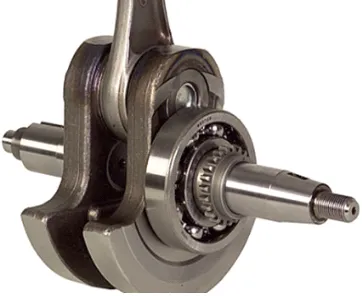
Crankshaft is a component in an engine which converts the reciprocating motion of the piston
to the rotary motion. Where as in a reciprocating compressor, it converts the rotational motion
into reciprocating motion. In order to do the conversion between two motions, the crankshaft has
"crank throws" or "crankpins", additional bearing surfaces whose axis is offset from that of the crank,
to which the "big ends" of the connecting rods from each cylinder attach. The design of a crankshaft is
of 4 stroke single cylinder S.I engine. So that two revolution of crankshaft for each stroke. The peak
pressure acting on the engine crankshaft. The crankshaft of the located model is designed using CAD
SOFTWARE CATIA V5 with the accurate dimensions and material standards. CATIA V5 is one of
the best design software in design tools were we can easily design components based on it dimensions
and analysis in annoys with accurate results. In this project to compare the optimization of crank shaft
on two different materials( aluminum alloy & e-glass epoxy composite) .The results are taken and
evaluated with the given load conditions and following deformation results are shown.
1.Introduction
Today’s automotive industries are
faced with a number of issues, which require
them to be responsive in order to be
competitive. To be competitive, one has to
produce components with low cost and high
quality. The advent of high performance
computers, CAD tools and Optimization
techniques has helped realize the demand of
global market. With the help of Optimization
techniques and numerical methods, one can
design a component, create a solid model using
CAD tools, simulate the operating conditions
and find out if the component meets the
expectations and feasibility before starting the
actual production, thereby saving time and
Available online: http://edupediapublications.org/journals/index.php/IJR/ P a g e | 335
The general considerations in designing a
crankshaft are;
The type of loads and stresses caused by it,
selection of material, motion of parts or
kinematics of the crankshaft, form and size of
parts, convenient and economical features like
minimization of wear, and use of standard
parts. Failure of the Crankshaft will result in
the failure of the engine.
Figure 1: crankshaft
CRANK MECHANISM
A crank is an arm attached at a right angle to a
rotating shaft by which reciprocating motion is
imparted to or received from the shaft. It is
used to convert circular motion into
reciprocating motion, or vice versa. The arm
may be a bent portion of the shaft, or a separate
arm or disk attached to it. Attached to the end
of the crank by a pivot is a rod, usually called
a connecting rod . The end of the rod attached
to the crank moves in a circular motion, while
the other end is usually constrained to move in
a linear sliding motion.
The term often refers to a human-powered
crank which is used to manually turn an axle,
as in a bicycle crank set or a brace and bit drill.
In this case a person's arm or leg serves as the
connecting rod, applying reciprocating force to
the crank. There is usually a bar perpendicular
to the other end of the arm, often with a freely
rotatable handle or pedal attached.
A crankshaft related to crank is a mechanical
part able to perform a conversion
between reciprocating motion and rotational
motion. In a reciprocating engine, it
translates reciprocating motion of
the piston into rotational motion, whereas in
a reciprocating compressor, it converts the
rotational motion into reciprocating motion. In
order to do the conversion between two
motions, the crankshaft has "crank throws" or
"crankpins", additional bearing surfaces whose
axis is offset from that of the crank, to which
the "big ends" of the connecting rods from each
Available online: http://edupediapublications.org/journals/index.php/IJR/ P a g e | 336 It is typically connected to a flywheel to reduce
the pulsation characteristic of the four-stroke
cycle, and sometimes a torsional or vibrational
damper at the opposite end, to reduce
the torsional vibrations often caused along the
length of the crankshaft by the cylinders
farthest from the output end acting on the
torsional elasticity of the metal.
Large engines are usually multi cylinder to
reduce pulsations from individual
firing strokes, with more than one piston
attached to a complex crankshaft. Many small
engines, such as those found in mopeds or
garden machinery, are single cylinder and use
only a single piston, simplifying crankshaft
design.
I.C Engines
A crankshaft is subjected to enormous stresses,
potentially equivalent of several tones of force.
The crankshaft is connected to the fly-wheel
(used to smooth out shock and convert energy
to torque), the engine block, using bearings on
the main journals, and to the pistons via their
respective con-rods. An engine loses up to 75%
of its generated energy in the form of friction,
noise and vibration in the crankcase and piston
area. The remaining losses occur in the valve
train (timing chains, belts, pulleys, camshafts,
lobes, valves, seals etc.) heat and blow by.
Piston stroke
The distance the axis of the crank throws from
the axis of the crankshaft determines the
piston stroke measurement, and thus engine
displacement. A common way to increase the
low-speed torque of an engine is to increase the
stroke, sometimes known as "shaft-stroking."
This also increases the reciprocating vibration,
however, limiting the high speed capability of
the engine. In compensation, it improves the
low speed operation of the engine, as the
longer intake stroke through smaller valve(s)
results in greater turbulence and mixing of the
intake charge. Most modern high speed
production engines are classified as "over
square" or short-stroke, wherein the stroke is
less than the diameter of the cylinder bore. As
such, finding the proper balance between
shaft-stroking speed and length leads to better
results.
Engine configuration
The configuration, meaning the number of
pistons and their placement in relation to each
other leads to straight, V or flat engines. The
same basic engine block can sometimes be
Available online: http://edupediapublications.org/journals/index.php/IJR/ P a g e | 337 alter the firing order. For instance, the
90° engine configuration, in older
days sometimes derived by using six cylinders
of a V8 engine with a 3 throw crankshaft,
produces an engine with an inherent pulsation
in the power flow due to the "gap" between the
firing pulses alternates between short and long
pauses because the 90 degree engine block
does not correspond to the 120 degree spacing
of the crankshaft. The same engine, however,
can be made to provide evenly spaced power
pulses by using a crankshaft with an individual
crank throw for each cylinder, spaced so that
the pistons are actually phased 120° apart, as in
the GM 3800 engine. While most production
V8 engines use four crank throws spaced 90°
apart, high-performance V8 engines often use a
"flat" crankshaft with throws spaced 180°
apart, essentially resulting in two straight four
engines running on a common crankcase. The
difference can be heard as the flat-plane
crankshafts result in the engine having a
smoother, higher-pitched sound than
cross-plane (for example, IRL Indy Car
Series compared to NASCAR Sprint Cup
Series, or a Ferrari 355 compared to
a Chevrolet Corvette). This type of crankshaft
was also used on early types of V8 engines.
See the main article on cross plane crankshafts.
Engine balance
For some engines it is necessary to
provide counterweights for the reciprocating
mass of each piston and connecting rod to
improve engine balance. These are typically
cast as part of the crankshaft but, occasionally,
are bolt-on pieces. While counter weights add a
considerable amount of weight to the
crankshaft, it provides a smoother running
engine and allows higher RPM levels to be
reached.
1.8 Flying arms
In some engine configurations, the crankshaft
contains direct links between adjacent crank
pins, without the usual intermediate main
bearing. These links are called flying arms.
This arrangement is sometimes used
in V6 and V8 engines, as it enables the engine
to be designed with different V angles than
what would otherwise be required to create an
even firing interval, while still using fewer
main bearings than would normally be required
with a single piston per crank throw.
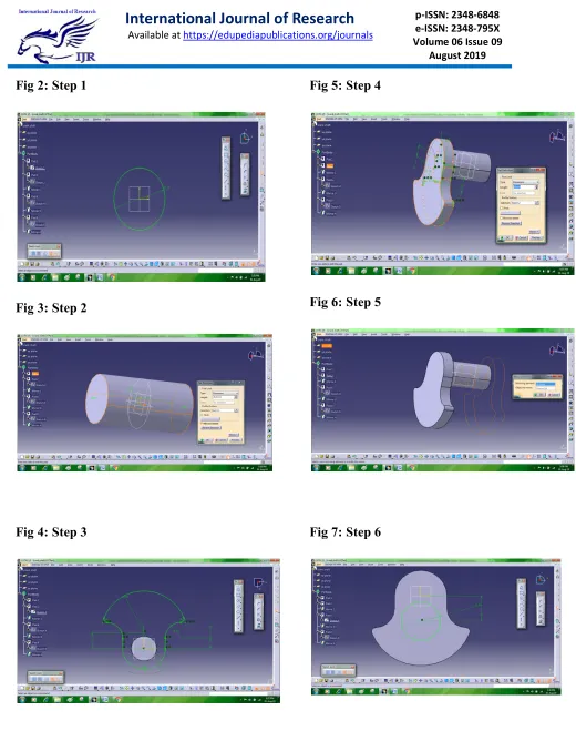
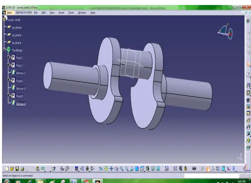
2. HOW TO DRAW CRANK SHAFT IN
Available online: http://edupediapublications.org/journals/index.php/IJR/ P a g e | 338
Fig 2: Step 1
Fig 3: Step 2
Fig 4: Step 3
Fig 5: Step 4
Fig 6: Step 5
Available online: http://edupediapublications.org/journals/index.php/IJR/ P a g e | 339
Fig 8: Step 7
Fig 9: Step 8
Fig 10: Step 9
Fig 11: Final model single crank shaft
3. INTRODUCTION TO FEA
Finite Element Analysis (FEA) was
first developed in 1943 by R. Courant, who
utilized the Ritz method of numerical analysis
and minimization of variation calculus to
obtain approximate solutions to vibration
systems. Shortly thereafter, a paper published
in 1956 by M. J. Turner, R. W. Clough, H. C.
Martin, and L. J. Top established a broader
definition of numerical analysis. The paper
centered on the "stiffness and deflection of
complex structures".
By the early 70's, FEA was limited to
expensive mainframe computers generally
owned by the aeronautics, automotive, defense,
and nuclear industries. Since the rapid decline
Available online: http://edupediapublications.org/journals/index.php/IJR/ P a g e | 340 increase in computing power, FEA has been
developed to an incredible precision. Present
day supercomputers are now able to produce
accurate results for all kinds of parameters.
FEA consists of a computer model of a
material or design that is stressed and analyzed
for specific results. It is used in new product
design, and existing product refinement. A
company is able to verify a proposed design
will be able to perform to the client's
specifications prior to manufacturing or
construction. Modifying an existing product or
structure is utilized to qualify the product or
structure for a new service condition. In case of
structural failure, FEA may be used to help
determine the design modifications to meet the
new condition.
There are generally two types of analysis that
are used in industry: 2-D modeling, and 3-D
modeling. While 2-D modeling conserves
simplicity and allows the analysis to be run on
a relatively normal computer, it tends to yield
less accurate results. 3-D modeling, however,
produces more accurate results while
sacrificing the ability to run on all but the
fastest computers effectively. Within each of
these modeling schemes, the programmer can
insert numerous algorithms (functions) which
may make the system behave linearly or
non-linearly. Linear systems are far less complex
and generally do not take into account plastic
deformation. Non-linear systems do account
for plastic deformation, and many also are
capable of testing a material all the way to
fracture.
FEA uses a complex system of points called
nodes which make a grid called a mesh. This
mesh is programmed to contain the material
and structural properties which define how the
structure will react to certain loading
conditions. Nodes are assigned at a certain
density throughout the material depending on
the anticipated stress levels of a particular area.
Regions which will receive large amounts of
stress usually have a higher node density than
those which experience little or no stress.
Points of interest may consist of: fracture point
of previously tested material, fillets, corners,
complex detail, and high stress areas. The mesh
acts like a spider web in that from each node,
there extends a mesh element to each of the
adjacent nodes. This web of vectors is what
carries the material properties to the object,
Available online: http://edupediapublications.org/journals/index.php/IJR/ P a g e | 341 A wide range of objective functions (variables
within the system) are available for
minimization or maximization:
Mass, volume, temperature
Strain energy, stress strain
Force, displacement,
velocity, acceleration
Synthetic (User defined)
There are multiple loading
conditions which may be
applied to a system. Some
examples are shown:
Point, pressure, thermal,
gravity, and centrifugal
static loads
Thermal loads from solution
of heat transfer analysis
Enforced displacements
Heat flux and convection
Point, pressure and gravity
dynamic loads
Each FEA program may
come with an element
library, or one is constructed
over time. Some sample
elements are:
Rod elements
Beam elements
Plate/Shell/Composite
elements
Shear panel
Solid elements
Spring elements
Mass elements
Rigid elements
Viscous damping elements
Many FEA programs also
are equipped with the
capability to use multiple
materials within the
structure such as:
Isotropic, identical
throughout
Orthotropic, identical at 90
degrees
General anisotropic,
Available online: http://edupediapublications.org/journals/index.php/IJR/ P a g e | 342
Types of Engineering Analysis
Structural analysis consists of linear and non-linear models. Linear models use simple parameters and assume that the material is not plastically deformed. Non-linear models consist of stressing the material past its elastic capabilities. The stresses in the material then vary with the amount of deformation as in.
Vibrational analysis is used to test a material against random vibrations, shock, and impact. Each of these incidences may act on the natural vibrational frequency of the material which, in turn, may cause resonance and subsequent failure.
Fatigue analysis helps designers to predict the life of a material or structure by showing the effects of cyclic loading on the specimen. Such analysis can show the areas where crack propagation is most likely to occur. Failure due to fatigue may also show the damage tolerance of the material.
Heat Transfer analysis models the conductivity or thermal fluid dynamics of the material or structure. This may consist of a steady-state or transient transfer. Steady-state transfer refers to constant thermo properties in the material that yield linear heat diffusion.
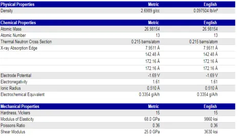
4.. Material properties
Available online: http://edupediapublications.org/journals/index.php/IJR/ P a g e | 343
Table 2:E-glass epoxy Material Properties
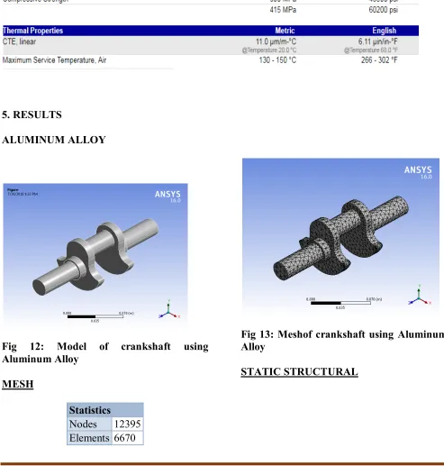
5. RESULTS
ALUMINUM ALLOY
Fig 12: Model of crankshaft using Aluminum Alloy
MESH
Statistics
Nodes 12395 Elements 6670
Fig 13: Meshof crankshaft using Aluminum Alloy
Available online: http://edupediapublications.org/journals/index.php/IJR/ P a g e | 344
Fig 14: Structural analysis of crankshaft using Aluminum Alloy
TOTAL DEFORMATION
Fig 15: Deformation of crankshaft using Aluminum Alloy
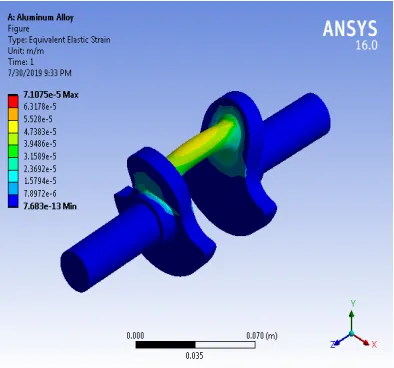
EQUIVALENT ELASTIC STRAIN
Fig 16: Equivalent Elastic Strain Analysis Of Crankshaft
EQUIVALENT STRESS
Available online: http://edupediapublications.org/journals/index.php/IJR/ P a g e | 345
EPOXY E GLASS UD
TOTAL DEFORMATION
Fig 18: Deformation OfEpoxy E Glass Ud Crankshaft
EQUIVALENT ELASTIC STRAIN
Fig 19: Equivalent Elastic Strain Analysis OfEpoxy E Glass Ud Crankshaft
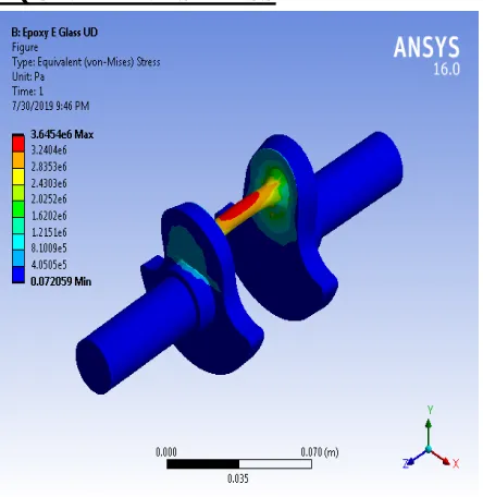
EQUIVALENT STRESS
Fig 20:Equivalent Stress Analysis OfEpoxy E Glass Ud Crankshaft
GRAPHS
Available online: http://edupediapublications.org/journals/index.php/IJR/ P a g e | 346 Graph 2: Graph of Equivalent Elastic Strain
GRAPH 3:Graph of Equivalent Stress
6. CONCLUSION
Parameters Aluminum
Alloy
Epoxy E
Glass Total
Deformation
7.4944E-07 5.7482E-07
Equivalent Elastic Strain
7.1075E-05 5.2502E-05
Equivalent Stress
3.6586E+06 3.6454E+06
Table 3: Comparison of Aluminum Alloy and Epoxy E Glass
The deformation is less in Epoxy E Glass when compared to that of the Aluminum Alloy, the maximum stress is induced in aluminum is more when compared to that of the aluminum alloy, the strain is more in Epoxy E Glass when compared to that of Aluminum Alloy
Hence the Epoxy E Glass is the best.
REFERENCES
[1] K. L. Napolitano, W. Grippo, J. B. Kosmatka and C. D. Johnson, “A comparison of two cocured damped composite torsion shafts”, Composite Structures, Vol. 43, 1998, pp. 115- 125.
[2] J. M. Biggerstaff and J. B. Kosmatka, “Damping Performance of Cocured Composite Laminates with Embedded Viscoelastic Layers”, Journal of Composite Materials, Vol. 32, No.21/ 1998.
[3] Jin Kook Kim, Dai Gil Lee, and Durk Hyun Cho, 2001, “Investigation of Adhesively Bonded Joints for Composite Propeller shafts”, Journal of Composite Materials, Vol.35, No.11, pp. 999-1021.
[4] T. E. Alberts and Houchun Xia, “Design and Analysis of Fiber Enhanced Viscoelastic Damping Polymers”, Journal of Vibration and Acoustics, Vol. 117, October 1995, pp. 398- 404.
[5] K. J. Buhariwala and J. S. Hansen, "Dynamics of Viscoelastic Structures", AIAA Journal, Vol. 26, February 1988, pp 220-227.
[6] J. B. Kosmatka and S. L. Liguore,
“Review of Methods for Analyzing
Available online: http://edupediapublications.org/journals/index.php/IJR/ P a g e | 347 Journal of Aerospace Engineering, Vol.6, No.3,
July 1993, pp. 268- 283.
[7] T. C. Ramesh and N. Ganesan, “Vibration and Damping Analysis of Cylindrical Shells with Constrained Damping Treatment- A Comparison of Three Theories”, Journal of Vibration and Acoustics, Vol. 117, April 1995, pp. 213 – 219.
[8] Conor D. Johnson and David A. Kienholz, “Finite Element Prediction of Damping in Structures with Constrained Viscoelastic Layers”, AIAA Journal, Vol. 20, No. 3, September 1982, pp. 1284-1290.
[9] N. T. Asnani and NaiyarAlam, " Vibration and Damping Analysis of a Multilayered Cylindrical Shell, Part I: Theoretical Analysis", AIAA Journal, Vol. 22, No. 6, June 1984, pp 803-810
[10] N. T. Asnani and NaiyarAlam, " Vibration and Damping Analysis of a Multilayered Cylindrical Shell, Part II: Numerical Results", AIAA Journal, Vol. 22, No. 7, July 1984, pp 975-981
[11] D. A. Saravanos and J. M. Pereira, “Dynamic Characteristics of Specialty Composite Structures with Embedded Damping Layers”, Journal of Vibration and Acoustics, Vol. 117, January 1995, pp. 62-69.
[12] C .D. Johnson, “Design of Passive Damping Systems”, Transactions of the ASME, Vol. 117, June 1995, pp. 171-176.
[13] H. V. Panossian, "Structural Damping Enhancement Via Non- Obstructive Particle Damping Technique", Journal of Vibration and Acoustics, Vol.114, January 1992, pp.101-105.
[14] M. A. Trindade, A. Benjeddou and R. Ohayon, “ Modeling of Frequency- Dependent Viscoelastic Materials for Active- Passive Vibration Damping”, Journal of Vibration and Acoustics, Vol.122, April 2000, pp.169-174.
[15] John F. Baldwin and Stanley G. Hutton, " Natural Modes of Modified Structures", AIAA Journal, Vol. 23, No. 11, November 1985, pp.1737-1743.
[16] M. L. Soni and F. K. Bogner, "Finite Element Vibration Analysis of Damped Structures", AIAA Journal, Vol. 20, No. 5, May 1982, pp. 700-707.
[17] Y. P. Lu, B. E. Douglas and E. V. Thomas, “Mechanical Impedance of Damped Three- Layered Sandwich Rings”, AIAA Journal, Vol. 11, No. 5, March 1973, pp. 300-304.
[18] E. R. Marsh and L. C. Hale, “Damping of Flexural Waves with Imbedded Viscoelastic materials”, Journal of Vibration and Acoustics, Vol.120, January 1998, pp. 188-198.
[19] I. C. Finegan and R. F. Gibson, "Improvement of Damping at the Micro mechanical Level in Polymer Composite Materials under Transverse Normal Loading by the Use of Special Fiber Coatings", Journal of Vibration and Acoustics, Vol.120, April 1998, pp. 623-627.