Available online: https://edupediapublications.org/journals/index.php/IJR/ P a g e | 758
A novel method of Power Quality Improvement and Reactive
Power Compensation in a Grid Connected System for Non-Linear
Loads Using DSTATCOM for Induction Motor Drive Applications
A.Udai Kiran & G.Srinivas
M-tech Student Scholar Department of Electrical & Electronics Engineering, GOKUL GROUP OF INSTITUTION, PIRIDI; VIZIANAGARAM (Dt); A.P, India.
Assistant Professor Department of Electrical & Electronics Engineering, GOKUL GROUP OF INSTITUTION, PIRIDI; VIZIANAGARAM (Dt); A.P, India
Abstract: In this paper an attempts has been to analyses the role of DSTATCOM (Distribution static compensator) and located at load side in the distribution system, which can to eliminating or overcome the problems of source side like voltage sag and interruption etc... In order to maintain the power system quality the DSTATCOM will absorb and provide reactive power to mitigate voltage sag, swell, interruption and improve power factor in various conditions. The use of STATCOM for solving power quality problems due to voltage sags, flickers, swell etc., has been suggested. The purpose of STATCOM is to provide efficient voltage regulation during short duration of induction motor starting and thus prevent large voltage dips. The D-STATCOM fed with induction motor performance can be analyzed by using MATLAB /SIMULINK software.
Key words: D-STATCOM (Distributed Static Synchronous Compensator); Induction Motor Drive Voltage Sag; Power quality.
I. INTRODUCTION
The power electronic devices, due to their inherent non-linearity draw harmonics and reactive power from the power supply. In three phase systems, they sometimes also cause unbalance and draw excessive neutral currents. The injected harmonics, reactive power burden, unbalance and excessive neutral currents lead to low system efficiency and poor power factor. In addition to this, the power system is subjected to various transients like voltage sags, swell, flickers etc [1]. These transients would affect the voltage at distribution levels. Excessive reactive power of loads would increase the generating capacity of generating stations and increase the transmission losses in lines [2]. Hence supply of reactive power at the load ends becomes essential. Power quality has become an important issue since many loads at various distribution ends like adjustable speed drives, process industries, printers, domestic utilities, computers, microprocessors based equipments etc. have become intolerant to voltage fluctuations, harmonic content and interruptions [3-5]. Power quality mainly deals with issues like maintaining a fixed voltage at the point of common coupling for various distribution voltage levels irrespective of voltage fluctuations, maintaining near unity power factor power draw from the supply, blocking
and current unbalance from passing upwards from various distribution levels, reduction of voltage and current harmonics in the system and suppression of excessive supply neutral current [6].
At present, a wide range of flexible AC controller which is capitalized on newly available power electronic components is emerging for custom power application. FACTS components have been found as the most efficient and economical way to control the power transfer in interconnected AC transmission systems [7]. Among these distributions static compensator is used in the present work. The fast response of DSTATCOM makes it efficient solution s for improving the power quality in distribution system [8-10].
One useful option is to use DSTATCOM in shunt configuration with the main system so that the full capacity of generating sets is efficiently utilized .DSTATCOM employs a voltage source converter (VSC) and generates capacitive and inductive reactive power internally [11]. Its control is very fast and has the capability to provide adequate reactive compensation to the system. DSTATCOM can be effectively utilized to regulate voltage for one large rating motor or for a series of small induction motors starting simultaneously. Induction motor loads draw large starting currents (5- 6times) of the full rated current and may affect working of sensitive loads [12][13].
II. POWER QUALITY
Power quality is defined as the concept of powering and grounding sensitive. Equipment in a matter that is suitable to the operation of that equipment.
Available online: https://edupediapublications.org/journals/index.php/IJR/ P a g e | 759 concern with a deviation from the ideal current. Current
should be in phase with the voltage.
Equipment produces more current disturbances than it used to do both low and high power equipment is more and more powered by simple power electronic converters which produce a broad spectrum of distortion there are indications that the harmonics distortion in the power system is rising, but no conclusive results are obtained due to the lack of large scale surveys. Also energy efficient equipment is a source of power quality disturbance adjustable speed drives and energy saving lamps are both important sources of waveform distortion and are also sensitive to certain type of power quality disturbances.
According to IEEE standard 1100, “power quality is the concept of powering and grounding sensitive equipment in amanner that is suitable to the operation of that equipment”.
a) Power quality problems
There are so many problems related with quality of power. Here the main concern with the poor power quality with nonlinear loads. Non-linear loads can cause voltage and current distortion. That is it changes its shape other than sinusoidal.
b) Harmonic Distortion
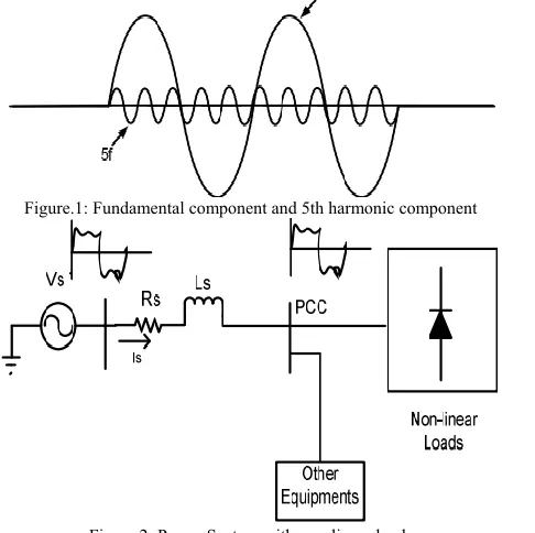
Harmonic components are those waveforms which have the frequency as an integer multiple of the fundamental. Any periodic waveform which is non-sinusoidal can be divided into fundamental and non fundamental components. Everynth harmonic will have a frequency n times that of fundamental frequency.
Figure.1: Fundamental component and 5th harmonic component
Figure.2: Power System with non-linear loads
Voltage at point of common coupling
(1) (2)
(3)
(4) Where
Non-linear loads draw reactive power. So input power factoris also get poor.
Line current and Total Harmonic Distortion (THD)
(5)
(6)
(7)
(8)
If we remove fundamental, then only ripple will be left
(9)
(10)
(11) III. PRINCIPLE OF D-STATCOM
It is shunt connected at the distribution side of the power systems. A D-STATCOM is a controlled reactive source,which includes a Voltage Source Converter (VSC) and a DClink capacitor connected in shunt, capable of generating and/or absorbing reactive power. The operating principles ofa D-STATCOM are based on the exact equivalence of the conventional rotating synchronous compensator.
Available online: https://edupediapublications.org/journals/index.php/IJR/ P a g e | 760 voltage, then there is no reactive power exchange. It there
difference between these voltages the only reactive power exchange occurs. The control strategies studied in this paper are applied with a view to studying the performance of a D-STATCOM for reactive power compensation and harmonic mitigation.
Figure.3: Power system with D-STATCOM
Configuration and operation of DSTATCOMD-STATCOM has 3-phase voltage source converter, capacitor at DC side of inverter is connected with the electrical system at the PCC. The instantaneous controllable3-phase output voltage is generated from DC voltage at fundamental frequency. The pulse is generated by the hysteresis current controllers which takes the difference of reference current and actual source current and minimizes the error and controls the current and generate 3-phase output voltage and injects capacitive or inductive current according to the nature of load.
IV. MATHEMATICAL EXPRESSION FOR SYSTEM
Total instantaneous power delivery drawn by non-linear load
(12) Real power supplied by source-
(13) Reactive power supplied by source-
(14) Real power drawn by the load-
(15) Reactive power drawn by the load-
(16) Real power supplied by the D-STATCOM-
(17)
Reactive power supplied by D-STATCOM-
(18) Where 𝑃𝑙𝑜𝑠𝑠component of STATCOM
From the single line diagram Figure 2
(19) When the phase of 𝑉𝑆𝑇𝐴𝑇𝐶𝑂𝑀 is in quadrature
with 𝐼𝑆𝑇𝐴𝑇𝐶𝑂𝑀 without injecting real power the
D-STATCOM canachieve the voltage sag mitigation. The shunt injecting current𝐼𝑆𝑇𝐴𝑇𝐶𝑂𝑀 and 5 in Figure 3 can be expressed as equation (20and 21)
(20)
(21)
(22) Where
V. CONTROL STRATEGY
Figure.4: Control Strategy to generate pulses
VI. MATHEMATICAL MODELING The direct and quadrature axis component of current are:
(23)
Available online: https://edupediapublications.org/journals/index.php/IJR/ P a g e | 761 (25)
b) Hysteresis Current Controller
In conventional hysteresis band (HB) current control, the switching signal is sent to the IGBT at the same arm (T1 andT4). The output of the HBC is directly connected to the transistor T1 and reverse is connected to the T4, therefore the transistor in the same leg is not simultaneously ON or OFF.IGBT are self commutated. Hysteresis Current Controller compares the actual and reference current and generates pulses for the inverter. If
(26) If
(27)
VII. INDUCTION MOTOR DRIVE
An electrical motor is such an electromechanical device which converts electrical energy into a mechanical energy. In case of three phase AC operation, most widely used motor is three phase induction motor as this type of motor does not require any starting device or we can say they are selfstarting induction motor. For better understanding the principle of three phase induction motor, the basic constructional feature of this motor must be known to us. This Motor consists of two major parts: Stator: Stator of three phase induction motor is made up of numbers of slots to construct a 3 phase winding circuit which is connected to 3 phase AC source. The three phase winding are arranged in such a manner in the slots that they produce a rotating magnetic field after 3Ph. AC supply is given to them. Rotor: Rotor of three phase induction motor consists of cylindrical laminated core with parallel slots that can carry conductors. Conductors are heavy copper or aluminum bars which fits in each slots & they are short circuited by the end rings. The slots are not exactly made parallel to the axis of the shaft but are slotted a little skewed because this arrangement reduces magnetic humming noise & can avoid stalling of motor.
The induction motor has advantage as simple construction, reliability, raggedness and low cost has found very wide industrial appellations. Furthermore, in contrast to the commutation Dc motor, it can be used in aggressive or volatile environments since there are no problems with spark and corrosion. These advantages, however, are occupied by control problems when using
induction motor in speed regulated industrial drives. These advantages, however, are occupied by control problems when using induction motor in speed regulated industrial drives. Speed control (v/f control) of induction motor requires two stage conversion (ac-dc and dc-ac), but most of the classical inverters gives poor performance.
Fig.5. 3- Phase Induction motor drive VIII. MATLAB/SIMULATION RESULTS
Available online: https://edupediapublications.org/journals/index.php/IJR/ P a g e | 762 Fig.7. Simulation waveform for Grid reference current
Fig.8. Simulation waveform for Grid phase and reference currents
Fig.9. Reactive power generated by Grid
Fig.10. Reactive power demanded by load
Fig.11. Reactive power supplied by D-STATCOM
Fig.12. Source current, Load current, D-STATCOM injected harmonic current and Source voltage
Available online: https://edupediapublications.org/journals/index.php/IJR/ P a g e | 763 Fig.14. Load current THD
Fig.15 Source current THD
Fig.16. Matlab/Simulink circuit for Power system with D-STATCOM with Induction Motor Drive
(a) Stator Current
Available online: https://edupediapublications.org/journals/index.php/IJR/ P a g e | 764 (c) Torque
Fig.17. Simulation waveforms for Induction motor Stator current, Speed and Torque
IX. CONCLUSION
Theobjective of work is to study the performance of D-statcom for mitigating voltage sag, interruption, and to improve thepower quality in distribution network.The simulation results showthat the performance of DSTATCOM system has beenfound to be satisfactory for improving the power quality atthe consumer premises. DSTATCOM control algorithm isflexible and it has been observed to be capable of correctingpower factor to unity, eliminate harmonics in supplycurrents and provide load balancing. It is also able toregulate voltage at PCC. The control algorithm ofDSTATCOM has an inherent property to provide a self supportingDC bus of DSTATCOM. It has been found thatthe DSTATCOM system reduces THD in the supplycurrents for non-linear loads. The proposed D-STATCOM is further connected with induction motor drive is an application. In this work the motor stator current, speed and torque proved its good performance.
REFERENCES
[1] VeeraiahKumbha, N. Sumathi, “Power quality improvement of Distribution lines using DSTATCOM under various loading conditions,” International Journal of Modern Engineering Research (IJMER), Vol. 2, Issue. 5, Sep.-Oct. 2012.
[2] R.Sasi Kumar, P.Rajaguru, “POWER QUALITY IMPROVEMENT IN DISTRIBUTION SYSTEM USING DSTATCOM,” International Journal of Advanced Research in Electrical, Electronics and Instrumentation Engineering, Vol. 2, Issue 12, December 2013.
[3] Mithilesh Kumar Kanaujia, Dr. S.K. Srivastava, “ Power Quality Enhancement With D-STATCOM Under
Different Fault Conditions,” Vol. 3, Issue 2, March -April 2013, pp.828-833.
[4] Mohit Bajaj, Vinay Kumar Dwivedi, Ankit Kumar, Anurag Bansa, “Design and Simulation of DSTATCOM for Power Quality Enhancement in Distribution Networks under Various Fault Condition,” International Journal of Emerging Technology and Advanced Engineering, Volume 3, Issue 4, April 2013).
[5] Dinesh Kumar and Rajesh, “Modeling, Analysis and Performance of a DSTATCOM for Unbalanced and Non-Linear Load”, IEEE/PES Conference on Transmission and Distribution conference and Exhibition Asia and pacific, Publication, pp. 1 – 6, 2005.
[6] Vandana S Pal, Joy. “Reactive power compensation and in a lossless transmission line by the application of Statcom”, Proceedings of Second IRF International Conference, Cochin, India, and ISBN: 978-93-84209-43-8, (2014).
[7] Walmir Freitas, Andre Morelato, WilsunXuand Fujio Sato, “Impacts of AC Generators and D-DSTATCOM Devices on the Dynamic Performance of Distribution Systems”, IEEE Transactions on Power Delivery, pp. 1493 – 1501, 2005.
[8] M. G. Molina, P. E. Mercado, “Control Design and Simulation of D-DSTATCOM with Energy Storage for Power Quality Improvements”, IEEE/PES Conference on Transmission and Distribution Conference and Exposition Latin America, Venezuela,pp.1 - 7, 2006.
[9] S. Srikanthan and M. K. Mishra, “DC capacitor voltage equalization in neutral clamped inverters for DSTATCOM application,” IEEE Trans. Ind. Electron., vol. 57, no. 8, pp. 2768–2775, Aug. 2010.
[10] S. Srikanthan and M. K. Mishra, “An improved hysteresis current control of three level inverter for DSTATCOM application,” in Proc. Nat. Power Electron. Conf., IISc Bangalore, India, Dec. 2007, pp. 1–6.
[11] L. Zhang, C. Shen, M. L. Crow, L. Dong, S. Pekarek, and S. Atcitty, “Performance indices for the dynamic performance of FACTS and FACTS with energy storage,” Electric Power Components and Systems, vol. 33, no. 3, pp. 299–314, 2005.
[12] P. M. Meshram, B.Y.Bagde, R.N.Nagpure, “A Novel FACTS Device for the Improvement of Power Quality of the Supply”,2nd International Conference on Electrical Engineering and Electronics, Computer, Telecommunications and Information Technology (ECTI-CON 2005), vol.1, pp. 775-778,2005.