Simulation Study for Reactive Power
Compensation Using STATCOM
Neha Agashe
1, Dr. R.D.Kulkarni
2, A.R.Thorat
3PG Student, Dept. of Electrical Engineering, Rajarambapu Institute of Technology, Islampur, Sangli, India1
Scientific Officer ’H’ and Head, EFS, RED, Bhabha Atomic Research Centre (BARC), Mumbai, India2
Assistant Professor, Dept. of Electrical Engineering, Rajarambapu Institute of Technology, Islampur, Sangli, India3
ABSTRACT: The STATCOM (Static Synchronous Compensator) is the shunt connected FACTS devices which are connected to line via voltage source converter. Use of FACTS device is a best solution to mitigate the problem of reactive power compensation without construction of new transmission lines. The STATCOM can be used to improve power quality, power factor, system voltage profile, reactive power compensation. This paper develops the vector control strategy for improvement of power factor of the system. The developed control strategy improves the power factor of the system to almost unity.
KEYWORDS: FACTS, STATCOM, Controller design, PWM
I. INTRODUCTION
The increasing demand of electricity with high power quality along with more reliable and secure power system is fulfilled by providing the electricity which operates more flexibly and with best utilization. This increasing demand can be fulfilled either by installing new transmission lines or by increasing power transfer capability of the transmission line. The effective and economical solution is to increase transfer capability of transmission line giving attention to more utilization. To operate the power system in a flexible manner, controlling action should be made fast by utilizing the advance research and development in power electronics technology. The power transmission capacity has been enhanced without exceeding the thermal limit of transmission line and is achieved by incorporating Flexible ACTransmission System (FACTS) technology [1][2].
The compensator has two effects which appeared immediately. The first one is it alters no load supply point voltage and second is it modifies sensitivity of supply point voltage to load reactive power. There are two types of compensators, active and passive compensators. Normally the passive compensators include the devices which are permanently connected for step less variation of reactive power. Generally shunt devices are included in active compensators. These compensators maintain constant voltage at the bus terminals to which they are connected. The FACTS devices in the second generation are static compensators which consist of half controlled devices i.e. of thyristor based and fully controlled devices such as STATCOM, SVC, SSSC, etc. [1]
Basically there are four types of FACTS controllers: A] Shunt Controller
B] Series Controller C] Shunt-Series Controller D] Series-Series Controller
The series controller injects the voltage in series with the transmission line with any phase angle according to driving voltage to control the line current. The shunt controller draws or injects the current into the power system. The combination of shunt and series controller could inject the current via shunt controller of the system and injects the voltage via series controller of the system. These are coordinately control. The combined Series-Series controller provides independent reactive power compensation with the transmission of real power via DC link. In multiline transmission system these types of controller are used which controlled coordinately. The list of all controllers is given in Table I.
The STATCOM is shunt connected device which is used for compensation, either by injecting or absorbing reactive power. Many researchers contributed their research on reactive power compensation. In this paper the STATCOM is controlled by vector control method. The vector control strategy is mainly used for controlling three phase induction motor. The fast response is achieved by controlling flux and torque producing components.
The paper is divided into five sections. Section I deals with introduction of FACTS devices whereas Section II discusses the operation and characteristics of STATCOM. Section III describes the control strategy used for STATCOM along with transformations. Results are discussed in Section IV. The conclusions of the work are highlighted in Section V.
TABLE I. LIST OF FACTS CONTROLLER
Types of FACTS
Controllers Sub-classes of FACTS Controllers
Shunt Controller
1.Static Synchronous Compensator (STATCOM) 2.Static Synchronous Generator (SSG) 3.Battery Energy Storage System (BESS) 4.Thyristor Controlled Reactor (TCR) 5.Thyristor Switched Reactor (TSR) 6.Thyristor Switched Capacitor (TSC)
Series Controller
1.Static Synchronous Series Compensator (SSSC) 2.Thyristor Controlled Series Capacitor (TCSC) 3.Thyristor Switched Series Capacitor (TSSC) 4.Thyristor Controlled Series Reactor (TCSR)
Combined
Series-Series Controller I. Interline Power Flow Controller (IPFC)
Combined Shunt-Series Controller
1. Unified Power Flow Controller (UPFC)
2. Thyristor Controlled Phase Shifting Transformer (TCPST)
II. OPERATION AND CHARACTERISTICS OF STATCOM
to inverter. When synchronous machine is over excited it provides positive VARS behaving as capacitor and when the machine is under excited, it provide negative VARS and it behaves as inductor. STATCOM is a shunt connected device which is a DC to AC converter. Fig.1 shows the shunt compensator where Vta, Vtb and Vtc are the terminal
voltages [1].
The converter can control the magnitude and angle of the corresponding AC voltages. The reactive power flow is depends on the magnitude of voltage and the real power flow is depend on the angle whether it is lagging or leading. When current flowing through STATCOM is leads by 90° of other side, then it behaves as inductor whereas, when current lags by 90° of other side, then it acts as capacitor. The value of the capacitor should be properly chosen so that it can provide sufficient reactive power. Fig.2 shows the V-I characteristics of STATCOM [1][ 5][ 6].
Fig.1 Shunt Compensator [1]
Fig.2 V-I characteristics of STATCOM [1]
The V-I characteristics of STATCOM depends on the source voltage. STATCOM can also operate at the low voltage maintaining the maximum current independent of the voltage and also provide better reactive support even at the reduced voltage [7]. The desired controlled response of the STATCOM can be obtained by either changing the modulation index or by changing the DC bus voltage.
III. CONTROL STRATEGY
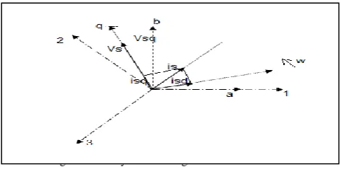
Three phase voltage, current, and STATCOM current are converted to two phase equivalent system which is known as stationary reference frame and further it transforms to rotating reference frame with the use of Phase Locked
Loop circuit (PLL).
Fig. 3 Stationary and Rotating Reference frame
From Fig. 3 it is seen that vector Vs is aligned on q-axis which describes the active power component and d- axis describes for reactive power component. The three phase voltage𝑉𝑠𝑎,𝑉𝑠𝑏,Vsc are converted into two phase Va, Vb with the help of (4) and (5). Simplified block diagram of the STATCOM is shown in Fig.4
Fig.4. Simplified diagram of stationary and rotating reference frame
Vs1= 2𝑉𝑠cos 𝑤𝑡 (1) Vs2= 2𝑉𝑠cos 𝑤𝑡 − 120 (2) Vs1= 2𝑉𝑠cos(𝑤𝑡 − 240) (3) Vsa=
3
2Vs1 (4) Vsb =
3
2 (Vs1− Vs3) (5)
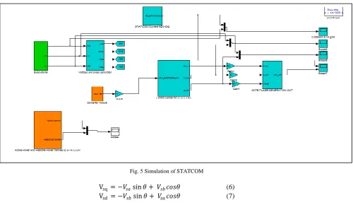
Further these two phase quantities are transferred to rotating reference frame i.e. d-q transformation. The d- axis leads a- axis by angle θ and q axis leads d-axis by 90°. Similarly line currents, converter current are transformed in d-q reference frame using (6) and (7). The outer voltage loop sets the reference for inner current loop. As the current loop is faster it is inside the voltage loop. By applying same control strategy STATCOM controller is simulated.
Fig. 5 Simulation of STATCOM
Vsq = −𝑉𝑠𝑎sin 𝜃 + 𝑉𝑠𝑏𝑐𝑜𝑠𝜃 (6) Vsd = −𝑉𝑠𝑏sin 𝜃 + 𝑉𝑠𝑎𝑐𝑜𝑠𝜃 (7)
Fig. 6 Control block diagram for STATCOM [8]
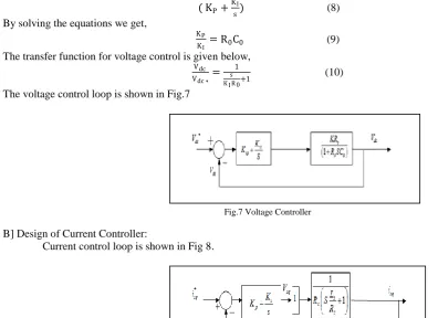
A] Voltage Controller design:
The design of voltage controller is done by pole zero cancellation method. The transfer function for the PI controller is given by,
( KP+ KI
s) (8) By solving the equations we get,
KP
KI = R0C0 (9) The transfer function for voltage control is given below,
Vdc Vdc ∗=
1 s K IR0+1
(10)
The voltage control loop is shown in Fig.7
Fig.7 Voltage Controller
B] Design of Current Controller:
Current control loop is shown in Fig 8.
Fig. 8 Current Controller
Current Controller designed with pole zero cancelation as, KP
KI = Ls
Rs (11)
isd isd∗ =
1 1+sR s
K i
(12)
.Accordingly the values of Kp and KI are selected.
IV. RESULTS AND DISCUSSION
The load is assumed as inductive load having power factor 0.69. The objective is to improve the power factor of system using developed control strategy. The DC bus voltage is maintained at 300V which is shown in Fig 9
Fig. 9 DC bus voltage
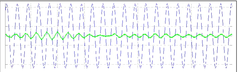
As the load is inductive the current lags the voltage by some angle. Fig 10 shows the system voltage and current before connection of the STATCOM.
Fig. 10 Phase a voltage and current before STATCOM connection
When the STATCOM is connected the system power factor improves to unity which is shown in Fig. 11. The result shows that when the STATCOM is not connected the current lags and after operation of circuit breaker the current and voltage of the source are appears in phase.
V. CONCLUSIONS
The STATCOM is used to improve the power factor of the system. The developed vector control strategy gives better results and fast response for power factor improvement. This simulation is done for fixed DC bus voltage and variable modulation index one can make for variable DC bus voltage and fixed modulation index depending on the application.
REFERENCES
[1] Flexible AC Transmission System (FACTS) by Yong Hua Song and Allan T. Johns published by The Institute of Engineering and Technology, London, United Kingdom second edition 2008.
[2] Narain G. Hingorani, Laszlo Gyugyi “Understanding FACTS concept and technology of Flexible AC transmission system” IEEE press Wiley edition 2000.
[3] Geza Joos, Luis Moran, Phoivos Ziogas “Performance analysis of PWM inverter Var compensator” IEEE Transactions on power electronics, vol. 6, no. 3, pp. 380-391 July 1991.
[4] Luis T. Moran, Phoivos D. Ziogas, and Geza Joos “Analysis and Design of a Three-phase Synchronous Solid-state Var Compensator” IEEE Transactions on industry applications, vol. 25, no. 4, pp. 598-608 July-August 1989.
[5] S.K.Das and J.K.Moharana “Modeling, Design Analysis and Simulation of Small Signal Control Strategy on a STATCOM for Reactive Power Compensation”, NSPEES-12, Sept.29-30, GIET, BBSR, pp. 17-23, 2012.
[6] Sushanta Kumar Sethy, and Pratap Chandra Pradhan“ Design and Simulation of Current and Voltage Linear Controller of a STATCOM for Reactive Power Compensation using variation of DC link voltage” Int. J. of Intelligent Computing and Applied Sciences Vol. 1, Issue 1, pp. 50-64 2013.
[7] Pranesh Rao , M. L. Crow , Zhiping Yang “STATCOM Control for Power System Voltage Control Applications” IEEE Trans. on power delivery, vol. 15, no. 4, pp. 1131-1137, October 2000.
[8] J.S.Siva Prasad, Tushar Bhavsar, Rajesh Ghosh, G. Narayanan “Vector Control of three phase AC/DC front end converter” Sadhana vol.33, part 5, pp. 591-613 October 2008
[9] G.C.Cho, N.S.choi,C.T.Rim,and G.H.Cho, “ Modelling, Analysis and Control of STATIC VAR Compensator using three level inverter”, IEEE, Ind. Society, Annual Meet, pp. 837-843, 1992.
[10] J. K. Moharana,M. Sengupta,A. Sengupta “Design, Analysis and Implementation of a Small Signal Control Strategy on a 10 kVA STATCOM Prototype Connected to Inductive Load” J. Inst. Eng. India Ser. pp. 61–69 B (March–May 2013).