P Available online: https://edupediapublications.org/journals/index.php/IJR/a g e | 3610
TAGUCHI'S PARAMETER DESIGN APPROACH
AUTHOR 1
Vajjarapu Meghasri received the B.Tech degree in “Mechanical Engineering” from Srinivasa Institute of
Engineering and Technology, JNTU, Amalapuram, Andhra Pradesh, India, in 2015 year, and perusing M.Tech in CAD/CAM from BVC Institute of Technology and Science, Batlapalem, Amalapuram, Andhra Pradesh, India.
AUTHOR 2
Sri. K. Suresh, M.Tech, Assistant professor, BVC Institute of Technology and Science, Batlapalem, Amalapuram, Andhra Pradesh, India.
ABSTRACT
The objective of the paper is to obtain an optimal setting of CNC machining process parameters, cutting speed, feed rate resulting in optimal values of the feed and radial forces while machining P – 20 tool steel with TiN coated tungsten carbide inserts. The effects of the selected process parameters on the chosen characteristics and the subsequent optimal settings of the parameters have been accomplished using Taguchi’s parameter design approach.
The process parameters considered are – Cutting speed 3000rpm, 2500rpm and 2000rpm. Feed rate 200mm/min, 300mm/min and 400mm/min and depth of cut is 0.2mm, 0.3mm and 0.4mm.The effect of these parameters on the feed force, radial force are considered for analysis. The analysis of the results shows that the optimal settings for low values of feed and radial forces are high cutting speed, low feed rate and depth of cut. The thrust force and feed force are also taken experimentally using dynamometer for above Cutting speeds, feed rate and depth of cut. The optimal values for speed, feed rate and depth of cut are taken using Taguchi technique in Minitab software.
INTRODUCTION
Milling is the machining process of using rotary cutters to remove material from a work piece by advancing (or feeding) in a direction at an angle with the axis of the tool. It covers a wide variety of different operations and machines, on scales from small individual parts to large, heavy-duty gang milling operations. It is one of the most commonly used processes in industry and machine shops today for machining parts to precise sizes and shapes.
P Available online: https://edupediapublications.org/journals/index.php/IJR/a g e | 3611 operations, led to a new class of machine tools, multitasking machines (MTMs), which are purpose-built to provide for a default machining strategy of using any combination of milling and turning within the same work envelope.
TOOL CUTTING EDGE ANGLE
Influence on chip thickness: hmax = fz × sin Κr
D: Depth of cut, mm. W: Width of cut, mm. F: Feed rate, mm/min MRR = D x W x F cc/min.
LITERATURE SURVEY
PAPER 1 - Modeling of the Influence of Cutting Parameters on the Surface Roughness, Tool Wear and Cutting Force in Face Milling in Off-Line Process Control by Dražen Bajić* – Luka Celent – Sonja Jozić, University of Split, Faculty of Electrical Engineering, Mechanical Engineering and Naval Architecture, Croatia
PAPER 2 - OPTIMIZATION OF SURFACE ROUGHNESS IN FACE TURNING OPERATION IN MACHINING OF EN-8 by K. Adarsh Kumar, Ch.Ratnam, BSN Murthy, B.Satish Ben, K. Raghu Ram Mohan Reddy
PAPER 3 - Effect of machining conditions on MRR and surface roughness during CNC Turning of different Materials Using TiN Coated Cutting Tools – A Taguchi approach by H. K. Dave, L. S. Patel, H. K. Raval
PAPER 4 - Optimization of surface roughness in CNC end milling using response surface methodology and genetic algorithm by B. Sidda Reddy, J. Suresh Kumar, and K. Vijaya Kumar Reddy
P Available online: https://edupediapublications.org/journals/index.php/IJR/a g e | 3612
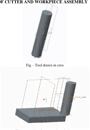
MODELING OF CUTTER AND WORKPIECE ASSEMBLY
Fig – Tool drawn in creo
Fig –assembly of cutter and workpiece
THRUST FORCE, TORQUE AND TEMPERATURE CALCULATIONS
MATERIAL – P 20 TOOL STEEL
Cutter dia = 25R5
Width of Workpiece = 75mm
No of Teeth on cutter = 4 = nc
P Available online: https://edupediapublications.org/journals/index.php/IJR/a g e | 3613
Width of chip = bc = 5mm
V = Cutting Velocity
rt = Chip Thickness Ratio
rt =
𝑡 𝑡𝑐 =
𝑣𝑐 𝑣 =
𝑙𝑐 𝑙
LC = Length of Chip = 7mm
L = Uncut Chip Length = 75mm
∝ = Rake Angle = 20°
𝛽 = Friction Angle = 40
∅ = Shear Angle
Speeds (rpm) Feed(mm/min) 1. 3000 200 2. 2500 300 3. 2000 400
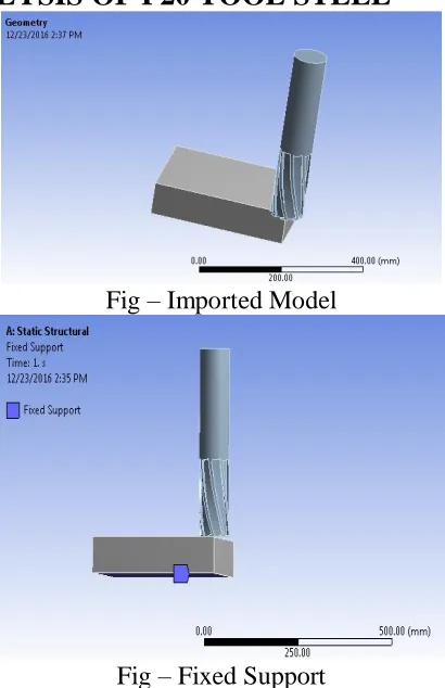
ANALYSIS OF CUTTING TOOL AND WORKPIECE ASSEMBLY
STRUCTURAL ANALYSIS OF P20 TOOL STEEL
Fig – Imported Model
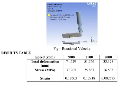
P Available online: https://edupediapublications.org/journals/index.php/IJR/a g e | 3614 Fig – Rotational Velocity
RESULTS TABLE
Speed (rpm) 3000 2500 2000
Total deformation (mm)
74.529 51.756 33.123
Stress (MPa) 37.205 25.837 16.535
Strain 0.18603 0.12918 0.082675
TAGUCHI PARAMETER DESIGN FOR CNC MILLING PROCESS
In order to identify the process parameters affecting the selected machine quality characteristics of CNC milling, the following process parameters are selected for the present work: cutting speed (A), feed rate (B) and depth of cut (C). the selection of parameters of interest and their ranges is based on literature review and some preliminary experiments conducted.
Selection of Orthogonal Array
The non-linear relationship among the process parameters, if it exists, can only be revealed if more than two levels of the parameters are considered. Thus, each selected parameter was analyzed at three levels. The process parameters and their values are given in table. It was also decided to study the three – factor interaction effects of process parameters on the selected characteristics while milling. These interactions were considered between cutting speed and feed rate (AXB), feed rate and depth of cut (BXC), cutting speed and depth of cut (AXC).
FACTORS PROCESS PARAMETERS LAVEL1 LEVEL2 LEVEL3
A CUTTING SPEED(rpm) 3000 2500 2000
B FEED RATE (mm/rev) 200 300 400
C DEPTH OF CUT(mm) 0.2 0.3 0.4
Table – Process parameters and their values
The experimentation is done by specifying process parameters for each job as per L9 orthogonal array using Taguchi technique.
P Available online: https://edupediapublications.org/journals/index.php/IJR/a g e | 3615
(rpm) (mm/rev) (mm)
1 3000 200 0.2
2 3000 300 0.3
3 3000 400 0.4
4 2500 200 0.3
5 2500 300 0.4
6 2500 400 0.2
7 2000 200 0.4
8 2000 300 0.2
9 2000 400 0.3
The feed forces are experimentally determined using a dynamometer.
Job no. Feed Force 1
(N)
Feed Force 2 (N)
1 1896 1636
2 1762 1762
3 1150 1285
4 1200 1369
5 1275 1432
6 1542 1542
7 1172 1056
8 1222 1581
9 1096 1364
The radial forces are experimentally determined using a dynamometer.
Job no. Radial Force
1 (N)
Radial Force 2 (N)
1 415 421
2 456 498
3 423 478
4 393 405
5 434 476
6 451 386
7 443 429
8 395 399
9 465 436
OPTIMIZATION OF PROCESS PARAMETERS USING TAGUCHI
METHOD TO MINIMIZE FORCES
P Available online: https://edupediapublications.org/journals/index.php/IJR/a g e | 3616 Fig Graph - Effect of milling parameters on feed forces for S/N ratio
The above graph shows the effect of each parameter Spindle Speed, Feed Rate and Depth of Cut on the feed forces. By observing, the S/N ratio is maximum at Spindle Speed 2000rpm, Feed Rate 400mm/rev and Depth of Cut 0.4mm.
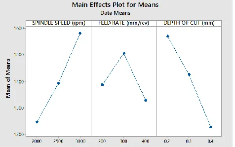
Fig Graph - Effect of milling parameters on feed forces for Means
ANALYSIS AND DISCUSSION
Regardless of the category of the performance characteristics, a greater S/N value corresponds to a better performance. Therefore, the optimal level of the machining parameters is the level with the greatest value.
Spindle Speed: - The effect of parameters spindle speed on the feed force is shown above figure for S/N ratio. The optimum spindle speed is 2000 rpm.
Feed Rate:- The effect of parameters Feed Rate on the feed force is shown above figure S/N ratio. The optimum Feed Rate is 400 mm/rev.
P Available online: https://edupediapublications.org/journals/index.php/IJR/a g e | 3617
MINIMIZATION OF RADIAL FORCE
Enter radial force values in the table
Fig– Observed radial Force Values
Stat – DOE – Taguchi - Analyze Taguchi Design – Select Responses
P Available online: https://edupediapublications.org/journals/index.php/IJR/a g e | 3618 Fig Graph - Effect of milling parameters on radial forces for S/N ratio
The above graph shows the effect of each parameter Spindle Speed, Feed Rate and Depth of Cut on the feed forces. By observing, the S/N ratio is maximum at Spindle Speed 2500rpm, Feed Rate 200mm/rev and Depth of Cut 0.2mm.
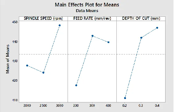
Fig Graph - Effect of milling parameters on radial forces for Means
Analysis and Discussion
Spindle Speed :- The effect of parameters spindle speed on the feed force is shown above figure for S/N ratio. The optimum spindle speed is 2500 rpm.
Feed Rate:- The effect of parameters Feed Rate on the feed force is shown above figure S/N ratio. The optimum Feed Rate is 200 mm/rev.
Depth of Cut:- The effect of parameters Depth of Cut on the feed force is shown above figure S/N ratio. The optimum Depth of Cut is 0.2 mm.
P Available online: https://edupediapublications.org/journals/index.php/IJR/a g e | 3619 P20 Tool Steel is considered for milling process which is used in die casting process and the influence of cutting parameters spindle speed, feed rate and depth of cut on thrust force and torque for the material is done theoretically using calculations and experimentally using Taguchi technique.
The parameters considered are cutting speed, feed rate and depth of cut. The cutting speeds are 3000rpm, 2500rpm and 2000rpm. The feed rates are 200mm/min, 300mm/min and 400mm/min and depth of cut is 0.2mm. From the analysis results, the displacement and stress values are less for all speeds. The stress values are very less compared with its yield stress value. So we can conclude that using P20 tool steel for die casting process is suitable.
Feed force and radial forces are taken experimentally using dynamometer by considering parameters cutting speed, feed rate and depth of cut. The optimal values for speed, feed rate and depth of cut are taken using Taguchi technique.
The optimal settings of various process parameters for CNC machined parts to yield optimal forces are: Speed – 2000rpm, Feed rate – 400mm/min, Depth of cut – 0.4mm when thrust force is taken (i.e.) feed force and when torque (i.e.) radial force is taken the optimal values are Speed – 2500rpm, Feed rate – 200mm/min, Depth of cut – 0.2mm.
REFERENCES
1. Modeling of the Influence of Cutting Parameters on the Surface Roughness, Tool Wear
and Cutting Force in Face Milling in Off-Line Process Control by Bajić, D, – Celent, L. – Jozić, S. Dražen Bajić* – Luka Celent – Sonja Jozić, Journal of Mechanical Engineering 58(2012)11, 673-682
2. Optimization of surface roughness in face turning operation in machining of EN-8 by K.
Adarsh Kumar, Ch.Ratnam, BSN Murthy, B.Satish Ben, K. Raghu Ram Mohan Reddy, International journal of engineering science & advanced technology Volume-2, Issue-4, 807 – 812
3. Effect of machining conditions on MRR and surface roughness during CNC Turning of
different Materials Using TiN Coated Cutting Tools – A Taguchi approach by H. K. Dave, L. S. Patel, H. K. Raval, International Journal of Industrial Engineering Computations
4. Optimization of surface roughness in CNC end milling using response surface
methodology and genetic algorithm by B. Sidda Reddy, J. Suresh Kumar, and K. Vijaya Kumar Reddy, International Journal of Engineering, Science and Technology
5. Prediction of surface roughness in end milling with gene expression programming by
Yang Yang, Xinyu Li, Ping Jiang, Liping Zhang, Proceedings of the 41st International Conference on Computers & Industrial Engineering
6. Furness, R.J., Ulsoy, A.G., Wu, C.L. (1996). Feed, speed, and torque controllers for
drilling. ASME Journal for Manufacturing Scientists and Engineers, vol. 118, p. 2–9.
7. Landers, R.G., Usloy, A.G., Furness, R.J. (2002). Process monitoring and control of
P Available online: https://edupediapublications.org/journals/index.php/IJR/a g e | 3620 Engineering (ISC), p. 109-115.
10. Oktem, H., Erzurumlu, T., Kurtaran, H. (2005). Application of response surface