A Compact Circularly Polarized Microstrip Ring Antenna Using
a Slotted Ground for GNSS Applications
Jiade Yuan* and Yujie Li
Abstract—A compact circularly polarized microstrip ring antenna is presented for Global Navigation Satellite systems (GNSS) application in this paper. The antenna consists of a ring-shaped slotted ground and a radiation patch which is fed by a T-like coupling feedline. The radiation patch is a square ring strip embedded within two inverted L-shaped strips and a rectangular strip. The overall size of the proposed antenna is 0.38×0.38×0.038λ3g (λg is the guide wavelength at the frequency of 1575 MHz).
The measured−15 dB|S11|bandwidth, 3 dB axial ratio (AR) bandwidth, and gain bandwidth of larger
than 5 dBi are in the frequency range of 1552–1623 MHz, which can fully cover the operating frequency band of BDS B1, GPS L1, and GLONASS L1.
1. INTRODUCTION
The operating frequency bands of GPS L1, BDS B1, and GLONASS L1 are commonly used in Global
Navigation Satellite Systems (GNSS). A right hand circular polarization (RHCP) antenna that can simultaneously covers the three bands with small dimension is highly demanded in GNSS terminals.
Several types of antennas are suitable to be used in GNSS terminals. Microstrip patch antenna is one of the popular antennas. In [1, 2], compact circularly polarized microstrip antennas are reported by embedding four unequal circular-patches or cutting slots in diagonal directions onto the square patches. The measured 3-dB axial-ratio (AR) bandwidths for [1] and [2] are 1.52% and 2.5%, respectively. Moreover, microstrip ring antennas have smaller dimension than microstrip patch antennas since their side length is about one quarter-wavelength and one half of the conventional patch antennas when they operate at fundamental mode [3–5]. In [3], a compact meandered microstrip ring antenna with four parasitic grounded patches and a slotted ground is reported, where a 3 dB AR bandwidth of 1.8% is obtained. Besides microstrip antenna, metamaterial antennas are also applied in GNSS recently since low profile and wide bandwidth can be easily obtained using metamaterial techniques [6–8]. In [6], a low profile broadband antenna is achieved where two crossed asymmetric dipoles are utilized as the primary radiating elements, and an artificial magnetic conductor is utilized as a reflector. In [7], a low-profile circularly polarized metasurface antenna is reported, and an impedance bandwidth of 17% and an AR bandwidth of 14.5% are achieved. However, though the antennas in [1–8] have small dimensions or better performances, they are hard to simultaneously satisfy small dimensions and better performances. In this paper, we propose a circularly polarized microstrip ring antenna with a small dimension for GNSS applications. The proposed antenna contains a slotted ground and a ring radiation patch with coupling feed. The embedding inverted L-shaped strips and rectangular patch on the radiation patch can improve the performance of axial ratio bandwidth (ARBW), and coupling feeding using T-like strip can improve the performance of impedance bandwidth (IBW). The etched ring slot in the ground can effectively reduce the ground size, and as results, a small slotted ground that is only slightly larger than the radiation patch is obtained, which can directly decrease the overall size of the proposed antenna.
Received 27 August 2019, Accepted 19 November 2019, Scheduled 5 December 2019
* Corresponding author: Jiade Yuan ([email protected]).
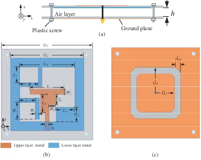
layers of IT-8350G substrate separated by the air; the slotted ground is printed on the lower surface of the lower layer; the radiation patch and T-like coupling feedline are printed on the lower and upper surfaces of the upper layer, respectively. The IT-8350G substrate has relative permittivity of 3.5, loss tangent of 0.0025, and thickness of 0.5 mm.
Air layer
Ground plane
h
Plastic screw
y x z
G4
G5
dcut (a)
(b) (c)
Figure 1. Geometry of the proposed antenna. (a) Cross sectional view, (b) top view and radiation patch (in blue), (c) bottom view (ground plane).
The radiation patch is a square ring strip, wherein an inverted L-shaped strip and a small rectangular patch are embedded on its upper left corner and lower right corner for improving circular polarization performance. Another inverted L-shaped strip whose only one end is shorted to the left side of the radiation patch is placed on the lower left side to adjust the coupling between the T-like shaped feedline and radiation patch, as shown in Fig. 1(b). Fig. 1(c) shows the bottom view of the proposed antenna, where a ring shaped slot is etched in the ground to form an inner patch and an outer ring.
The proposed antenna is simulated by the simulation software of ANSYS HFSS 18, and the optimized results are as follows (unit: mm): G1 = 70, G2 = 56, G3 = 42, G4 = 20, G5 = 15,
Ws= 4, Ld = 14, Lf = 8,Wf = 5, W1 = 14, W2 = 13, gs = 3,Ls= 26, W3 = 11, L1 = 12, L2 = 12,
L3 = 14,Wt= 3,dcut= 4, h= 6.
1.4 1.6 1.8 2.0 2.2 2.4 2.6 -30
-20 -10 0
|S
11
| (
d
B
)
Freq (GHz)
G4=17mm, G5=15mm
G4=20mm, G5=15mm
G4=23mm, G5=15mm
G4=20mm, G5=12mm
G4=20mm, G5=18mm
(a) (b)
Figure 2. Variations of|S11|and AR with different sizes of G4 and G5. (a)|S11|, (b) AR.
operating principle can be explained as that the outer ring of the slotted ground and the ring radiation patch form a Yagi-Uda-oriented double-ring antenna, and the inner patch plays a helpful role for further improving the directivity. Circular polarization can be obtained using the perturbation method by loading an inverted L-shaped strip and a rectangular patch in the upper left corner and lower right corner, respectively.
The structure parameters of the outer ring and inner patch, G4 and G5, are discussed on the
antenna performance. |S11| and AR at the boresight with varying G4 and G5 are computed, and the
results are shown in Figs. 2(a) and (b). When G4 increases from 17 to 23 mm with fixedG5 = 15 mm,
|S11|and AR first become better and then worse. Specifically, the AR is more sensitive to the variations of G4. When G5 increases from 12 mm to 18 mm with fixed G4 = 20 mm, |S11|and AR show visible variations. The reason can be explained as that the mutual coupling between the slotted ground and radiation patch varies with the variations ofG4 andG5. The optimal values for small AR and|S11|are
G4 = 20 mm andG5 = 15 mm.
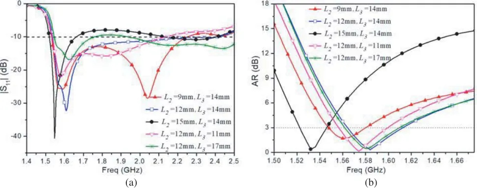
|S11|and AR at the boresight of the proposed antenna with varying lengths of L-shaped strip L2
and rectangular patch L3 are computed. As shown in Figs. 3(a) and (b), when L3 = 14 mm and L2
(a) (b)
coupling between the L-shaped strip and rectangular patch and the T-like shaped feedline, respectively, and result in the change of current distribution on the radiation patch.
3. RESULTS AND DISCUSSION
The proposed antenna is fabricated according to the simulated optimum dimension, and the prototype is shown in Fig. 4. |S11| is measured using R&S ZNB20 vector network analyzer. It can be observed in Fig. 5 that both the measured and simulated −15 dB bandwidths of |S11| can cover the frequency range of 1531–1697 MHz. The AR and radiation pattern are measured in our anechoic chamber. The simulated and measured results of AR at the boresight are shown in Fig. 6, and its measured 3 dB AR bandwidth is 1552–1623 MHz. In addition, the simulated and measured gains varying with frequency are also shown in Fig. 6. It can be seen that the measured gains at the center frequency of 1561, 1575, and 1602 MHz are 5.94, 6.37, and 5.97 dBi, respectively; the measured gain bandwidth of larger than 5 dBi is 1550–1638 MHz, and the peak gain is 6.45 dBi at the frequency of 1586 MHz. The discrepancies between the simulated and measured plots may be attributed to the unavoidable errors in the fabrication and measurement.
(a) (b)
(c)
Figure 4. The fabricated prototype. (a) Top view, (b) bottom view, and (c) side view.
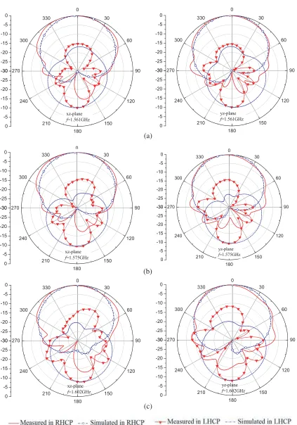
The simulated and measured patterns at the center frequency of BDS B1 (1.561 GHz), GPS L1
(1.575 GHz), and GLONASS L1 (1.602 GHz) inxz and yz planes are shown in Figs. 7(a), (b), and (c),
respectively. It can be observed that the measured and simulated results have good corroborations, and the measured front-to-back ratios (FBRs) at the frequencies of 1561, 1575, and 1602 MHz are 10.2, 9.5, and 8.2 dB, respectively. It is indicated that the proposed antenna has good directionality. The differences between the measured and simulated results are due to the fabrication tolerance and errors in measurement and simulation.
Figure 5. Simulated and measured|S11|of the proposed antenna.
Figure 6. Simulated and measured AR and gain of the proposed antenna.
operating bandwidth of GPS L1, BDS B1, and GLONASS L1. Meanwhile, the overall antenna size
is 0.38 ×0.38 ×0.038λ3
g, where λg is the guide wavelength at the frequency of 1575 MHz, and the
calculation of effective relative permittivity of the multilayer dielectric substrate can be referenced in [3].
Table 1 shows the comparison between the measured performances of the proposed GNSS antenna and other related antennas. Compared with the antenna in [1–3], the proposed antenna has higher gain and can cover more GNSS operating frequency band. In addition, though the antenna in [7] has wide bandwidth for both|S11|and AR, the proposed antenna can cover the same GNSS operating frequency
-30 -25 -20 -15 -10 60 90 120 150 180 210 240 270 300 -30 -25 -20 -15 -10 -5 0 xz-plane f=1.561GHz -30 -25 -20 -15 -10 60 90 120 150 180 210 240 270 300 -30 -25 -20 -15 -10 -5 0 yz-plane f=1.561GHz -30 -25 -20 -15 -10 -5
0 0 30
60 90 120 150 180 210 240 270 300 330 -30 -25 -20 -15 -10 -5 0 xz-plane f=1.575GHz -30 -25 -20 -15 -10 -5 0 0 30 60 90 120 150 180 210 240 270 300 330 -30 -25 -20 -15 -10 -5 0 yz-plane f=1.575GHz -30 -25 -20 -15 -10 -5
0 0 30
60 90 120 150 180 210 240 270 300 330 -30 -25 -20 -15 -10 -5 0 xz-plane f=1.602GHz -30 -25 -20 -15 -10 -5
0 0 30
60 90 120 150 180 210 240 270 300 330 -30 -25 -20 -15 -10 -5 0 yz-plane f=1.602GHz (a) (b) (c)
Table 1. Comparison of the antenna size and performances between the proposed and other existing antennas.
Ref. Overall size (λ3g) IBW ARBW Gain
(dBi)
Cover GNSS frequency band
[1] 0.68×0.68×0.03 1.556–1.612, 3.53%
1.568–1.592,
1.52% 5.25 GPS L1
[2] 0.581×0.581×0.048 1.565–1.655 5.6%
1.57–1.605
2.5% 4.65
GPS L1/
GLONASS L1
[3] 0.285×0.285×0.035 1.561–1.612 3.2%
1.566–1.594
1.8% 3.13 GPS L1
[7] 1.776×1.776×0.043 1.4–1.66 17%
1.4–1.62
14.5% 7
BDS B1/GPS L1/
GLONASS L1
This
work 0.385×0.385×0.038
1.515–2.524 49.3%
1.552–1.623
4.5% 6.45
BDS B1/GPS L1/
GLONASS L1
4. CONCLUSION
A compact wideband circularly polarized microstrip ring antenna is proposed. The novelty is the introduction of slotted ground and a joint design on the radiation patch and slotted ground. The proposed antenna has a small dimension of 0.38 ×0.38 ×0.038λ3g. All the measured −15 dB |S11|
bandwidth, 3 dB AR bandwidth, and 5 dBi gain bandwidth of the proposed antenna are in the frequency range of 1552–1623 MHz, which can fully cover the operating band of GPS L1, BDS B1, and GLONASS
L1. It promises to be a good antenna with small dimension and good performance, and can be used in
GNSS terminal devices.
ACKNOWLEDGMENT
This work was supported by the Natural Science Foundation of Fujian Province of China (2019J01638) and the Science and Technology Project Plan of Fuzhou of China (2018-G-89).
REFERENCES
1. Nasimuddin, Y. S. Anjani, and A. Alphones, “A wide-beam circularly polarized asymmetric-microstrip antenna,”IEEE Trans. Antennas Propag., Vol. 63, No. 8, 3764–3767, Aug. 2015. 2. Nasimuddin, X. Qing, and Z. N. Chen, “A compact circularly polarized slotted patch antenna for
GNSS applications,”IEEE Trans. Antennas Propag., Vol. 62, No. 12, 6506–6509, Dec. 2014. 3. Yuan, J., J. Zheng, and Z. Chen, “A compact meandered ring antenna loaded with parasitic patches
and a slotted ground for global navigation satellite systems,” IEEE Trans. Antennas Propag., Vol. 66, No. 12, 6835–6843, Dec. 2018.
4. Row, J. S., “Design of square-ring microstrip antenna for circular polarisation,” Electron. Lett., Vol. 40, No. 2, Jan. 2004.
5. Li, Y., S. Sun, and F. Yang, “A miniaturized Yagi-Uda-oriented double-ring antenna with circular polarization and directional pattern,” IEEE Antennas Wirel. Propag. Lett., Vol. 12, 945–948, Aug. 2013.
6. Ta, S. X. and I. Park, “Dual-band low-profile crossed asymmetric dipole antenna on dual-band AMC surface,”IEEE Antennas Wireless Propag. Lett., Vol. 13, 587–590, 2014.