Available online: https://edupediapublications.org/journals/index.php/IJR/ P a g e | 1804
Design of External Inductor for Improving Performance of Voltage
Controlled Dstatcom
D.Ramesh , G.Vishnu Vardhan Reddy , D. Naresh
Associate Professor, Dept of EEE, Nova College of Engineering and Technology, Hayathnagar, Rangareddy, TS, India Pg scholar, Dept of EEE (PE), Nova College of Engineering and Technology, Hayathnagar, Rangareddy, TS, India Assistant Professor, Dept of EE, Nova College of Engineering and Technology, Hayathnagar, Rangareddy, TS, India
ABSTRACT
In this Project, a new DSTATCOM topology with reduced dc link voltage is proposed. The distribution static compensator (DSTATCOM) is used for load compensation in power distribution network. In the presence of feeder impedance, the inverter switching distorts both the PCC voltage and the source currents. A new DSTATCOM topology with reduced dc link voltage is proposed. The topology consists of two capacitors: one is in series with the interfacing inductor of the active filter and the other is in shunt with the active filter. The series capacitor enables reduction in dc-link voltage while simultaneously compensating the reactive power required by the load, so as to maintain unity power factor without compromising DSTATCOM performance. The shunt capacitor, along with the state feedback control algorithm, maintains the terminal voltage to the desired value in the presence of feeder impedance with the reduction in dc-link voltage, the average switching frequency of the insulated gate bipolar transistor switches of the DSTATCOM is also reduced. Consequently, the switching losses in the inverter are reduced. Detailed design aspects of the series and shunt capacitors are discussed in this paper. A simulation study of the proposed topology has been carried out using MATLAB/SIMULINK. Finally a fuzzy logic controller is applied for further reduction of harmonics on source side.
KEYWORDS: DSTATCOM, Power quality, Active filter, Voltage control
I.INTRODUCTION
An increasing demand for high quality, reliable electrical power and increasing number of distorting loads may leads to an increased awareness of power quality both by customers and utilities. The most common power quality problems today are voltage sags, harmonic distortion and low power factor. Voltage sags is a short time (10 ms to 1 minute) event during which a reduction in r.m.s voltage magnitude occurs. It is often set only by two parameters, depth/magnitude and duration. The voltage sags magnitude is ranged from 10% to 90% of nominal voltage and with duration from half a cycle to 1 minimum.
Voltage sags is caused by a fault in the utility system, a fault within the customer’s facility or a large increase of the load current, like starting a motor or transformer energizing. Voltage sags are one of the most occurring power quality problems. For an industry voltage sags occur more often and cause severe problems and economical losses. Utilities often focus on disturbances from end-user equipment as the main power quality problems. Harmonic currents in distribution system can cause harmonic distortion, low power factor and additional losses as well as heating in the electrical equipment. It also can cause vibration and noise in machines and malfunction of the sensitive equipment.
Available online: https://edupediapublications.org/journals/index.php/IJR/ P a g e | 1805
control capabilities .There are different ways to enhance power quality problems in transmission and distribution systems. Among these, the D- STATCOM is one of the most effective devices.
II.SCHEME OF DSTATCOM
A D-STATCOM (Distribution Static Compensator), which is schematically depicted in Figure, consists of a two-level Voltage Source Converter (VSC), a dc energy storage device, a coupling transformer connected in shunt to the distribution network through a coupling transformer. The VSC converts the dc voltage across the storage device into a set of three-phase ac output voltages. These voltages are in phase and coupled with the ac system through the reactance of the coupling transformer. Suitable adjustment of the phase and magnitude of the D-STATCOM output voltages allows effective control of active and reactive power exchanges between the D-STATCOM and the ac system. Such configuration allows the device to absorb or generate controllable active and reactive power.
The VSC connected in shunt with the ac system provides a multifunctional topology which can be used for up to three quite distinct purposes:
1. Voltage regulation and compensation of reactive power;
2. Correction of power factor; and
3. Elimination of current harmonics.
Here, such device is employed to provide continuous voltage regulation using an indirectly controlled converter.
Fig1 Block diagram of D-STATCOM
The shunt injected current I
sh corrects the voltage sag by adjusting the voltage drop across the system impedance Z
th. The value of Ish can be controlled by adjusting the output voltage of the converter.
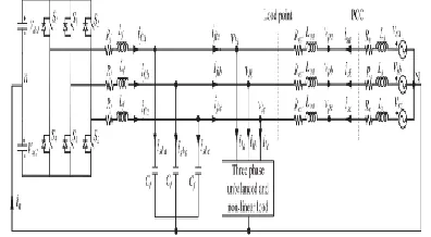
III.DSTATCOM IN THE POWER DISTRIBUTION SYSTEM
Fig 2. Three-phase equivalent circuit of DSTATCOM topology in the distribution system.
Available online: https://edupediapublications.org/journals/index.php/IJR/ P a g e | 1806
source. The DSTATCOM is connected at the point where load and Lext are connected. The DSTATCOM uses a three-phase four-wire VSI. A passive LC filter is connected in each phase to filter out high-frequency switching components. Voltages across dc capacitors, Vdc1 and Vdc2, are maintained at a reference value of Vdcref.
IV. EFFECT OF FEEDER IMPEDANCE ON VOLTAGE REGULATION
To demonstrate the effect of feeder impedance on voltage regulation performance, an equivalent source-load model without considering external inductor is shown in Fig.4.2. The current in the circuit is given as
where V s = Vs∠δ, V l = Vl∠0, Is = Is∠φ, and Zs =
Zs∠θs, with Vs, Vl, Is, Zs, δ, φ, and θs are rms source voltage, rms load voltage, rms source current, feeder impedance, load angle, power factor angle, and feeder impedance angle, respectively. The
three-phase average load power (Pl) is expressed as
Substituting V l and Is into (2), the load active power is
Rearranging (3), expression for δ is computed as
follows:
For power transfer from source to load with stable operation in an inductive feeder, δ must be positive and less than 90◦. Also, all the terms of the second part of (4), i.e., inside cos-1, are amplitude and will
always be positive. Therefore, the value of the second part will be between “0” and “π/2” for the entire operation of the load. Consequently, the load angle will lie between θs and (θs - π/2) under any load operation, and therefore, maximum possible load angle is θs.
Fig.3. Equivalent source-load model without considering external inductor.
The vector expression for source voltage is given as follows:
A DSTATCOM regulates the load voltage by injecting fundamental reactive current. To demonstrate the DSTATCOM voltage regulation capability at different supply voltages for different
Rs/Xs, vector diagrams using (5) are drawn in Fig.4.3. To draw these diagrams, load voltage Vl is taken as reference phasor having the nominal value OA (1.0 p.u.). With aim of making Vl = Vs = 1.0 p.u.,
locus of Vs will be a semicircle of radius Vl. Since the maximum possible load angle is 90◦in an
inductive feeder, phasor Vs can be anywhere inside curve OACBO. It can be seen that the value of θs + φ
must be greater than 90◦for zero voltage regulation. Additionally, it is possible only when power factor is
Available online: https://edupediapublications.org/journals/index.php/IJR/ P a g e | 1807
Fig.4. Voltage regulation performance curve of DSTATCOM at different Rs/Xs . (a) For Rs/Xs = 1. (b)
For Rs/Xs = √3. (c) For Rs/Xs = 3.73
Fig.4(a) shows the limiting case when Rs/Xs = 1, i.e., θs= 45◦. From (4), the maximum possible load angle is 45◦. The maximum value of angle, θs + φ, can be 135◦ when φ is 90◦. Hence, the limiting source current phasor OE, which is denoted by Islimit, will lead the load voltage by 90◦. Lines OC and AB show the limiting vectors of Vs and IsZs, respectively, with D as the intersection point. Hence, area under ACDA shows the operating region of DSTATCOM for voltage regulation. The point D has a limiting value of Vslimit = IsZs = 0.706 p.u. Therefore, maximum possible voltage regulation is 29.4%. However, it is impossible to achieve these two limits simultaneously as δ and φ cannot be maximum at the same time. Again if Zs is low, the source current, which will be almost inductive, will be enough to be realized by the DSTATCOM
Fig.4(b) considers case when Rs/Xs = √3, i.e., θs = 30◦. The area under ACDA shrinks, which shows that with the increase in Rs/Xs from the limiting value, the voltage regulation capability decreases. In this case, the limiting values of Vslimit and IsZs are found to be 0.866 and 0.5 p.u., respectively. Here, maximum possible voltage regulation is 13.4%. However, due to high-current requirement, a practical DSTATCOM can provide very small voltage regulation. Voltage regulation performance curves for more resistive grid, i.e.,θs =15◦, as shown in Fig.4(c), can be drawn similarly. Here, area under
ACDA is negligible. For this case, hardly any voltage regulation is possible.
V. DESIGN EXAMPLE OF EXTERNAL INDUCTOR
Here, it is assumed that the considered DSTATCOM protects load from a voltage sag of 60%. Hence, source voltage Vs = 0.6 p.u. is considered as worst
case voltage disturbances. During voltage
disturbances, the loads should remain operational while improving the DSTATCOM capability to mitigate the sag. Therefore, the load voltage during voltage sag is maintained at 0.9 p.u., which is sufficient for satisfactory operation of the load. In the present case, maximum required value of Iiml is 10
A. With the system parameters given in Table I, the
effective reactance after solving is found to be 2.2 Ω (Lsef= 7 mH). Hence, value of external inductance,
Lext, will be 6.7 mH. This external inductor is
Available online: https://edupediapublications.org/journals/index.php/IJR/ P a g e | 1808
Fig.5. Voltage regulation performance of DSTATCOM with external inductance.
With the external inductance while neglecting its ESR, Rs/Xsef will be 0.13, i.e., θsef = 83◦. Voltage regulation performance curves of the DSTATCOM in this case are shown in Fig.5.
VI. FLEXIBLE CONTROL STRATEGY
This sections presents a flexible control strategy to improve the performance of DSTATCOM in presence of the external inductor Lext. First, a dynamic reference load voltage based on the coordinated control of the load fundamental current, PCC voltage, and voltage across the external inductor is computed. Then, a proportional-integral (PI) controller is used to control the load angle, which helps in regulating the dc bus voltage at a reference value. Finally, three-phase reference load voltages are generated. The block diagram of the control strategy is shown in Fig.6
Fig.6. Block diagram of the proposed flexible control strategy.
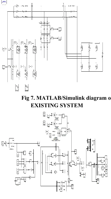
VII.SIMULATION RESULTS EXISTING RESULTS
Fig 7. MATLAB/Simulink diagram of EXISTING SYSTEM
Fig 8. controller subsystem
Fig 9. Simluation results of normal operation Source voltage, Source current, Load voltage, Load current,
Available online: https://edupediapublications.org/journals/index.php/IJR/ P a g e | 1809
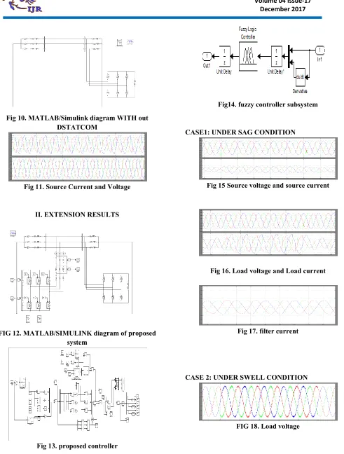
Fig 10. MATLAB/Simulink diagram WITH out DSTATCOM
Fig 11. Source Current and Voltage
II. EXTENSION RESULTS
FIG 12. MATLAB/SIMULINK diagram of proposed system
Fig 13. proposed controller
Fig14. fuzzy controller subsystem
CASE1: UNDER SAG CONDITION
Fig 15 Source voltage and source current
Fig 16. Load voltage and Load current
Fig 17. filter current
CASE 2: UNDER SWELL CONDITION
Available online: https://edupediapublications.org/journals/index.php/IJR/ P a g e | 1810
Fig 19. filter output voltage
Fig 20. Thd % of Source current without fuzzy controller
Fig21. Thd % of Source current with proposed fuzzy controller
CONCLUSION
This paper has presented design, operation, and control of a DSTATCOM operating in voltage control mode (VCM). After providing a detailed exploration of voltage regulation capability of DSTATCOM under various feeder scenarios, a benchmark design procedure for selecting suitable value of external inductor is proposed. An algorithm is formulated for dynamic reference load voltage magnitude generation. The DSTATCOM has improved voltage regulation capability with a reduced current rating VSI, reduced losses in the VSI and feeder. Also, dynamic reference load voltage generation scheme allows DSTATCOM to set different constant reference voltage during voltage disturbances. Simulation results validate the effectiveness of the proposed solution. The external inductor is a very simple and cheap solution for improving the voltage regulation, however it remains
connected throughout the operation and continuous voltage drop across it occurs. The future work includes operation of this fixed inductor as a controlled reactor so that its effect can be minimized by varying its inductance.
REFERENCES
[1] R. de Araujo Ribeiro, C. de Azevedo, and R. de Sousa, “A robust adaptive control strategy of active power filters for power-factor correction, harmonic compensation, and balancing of nonlinear loads,” IEEE Trans. Power Electron., vol. 27, no. 2, pp. 718–730, Feb. 2012.
[2] J. Pomilio and S. Deckmann, “Characterization and compensation of harmonics and reactive power of residential and commercial loads,” IEEE Trans. Power Del., vol. 22, no. 2, pp. 1049–1055, Apr. 2007.
[3] C.-S. Lam, W.-H. Choi, M.-C. Wong, and Y.-D. Han, “Adaptive dclink voltage-controlled hybrid active power filters for reactive power compensation,” IEEE Trans. Power Electron., vol. 27, no. 4, pp. 1758– 1772, Apr. 2012.
[4] B. Singh and J. Solanki, “Load compensation for diesel generator-based isolated generation system employing DSTATCOM,” IEEE Trans. Ind. Appl., vol. 47, no. 1, pp. 238–244, Jan.-Feb. 2011.
[5] B. Singh, P. Jayaprakash, S. Kumar, and D. Kothari, “Implementation of neural-network-controlled three-leg VSC and a transformer as three phase four-wire dstatcom,” IEEE Trans. Ind. Appl., vol. 47, no. 4, pp. 1892–1901, Jul.-Aug. 2011. [6] J. Liu, P. Zanchetta, M. Degano, and E. Lavopa, “Control design and implementation for high performance shunt active filters in aircraft power grids,” IEEE Trans. Ind. Electron., vol. 59, no. 9, pp. 3604–3613, Sep. 2012.