ISSN (Print) : 2320 – 3765 ISSN (Online): 2278 – 8875
I
nternational
J
ournal of
A
dvanced
R
esearch in
E
lectrical,
E
lectronics and
I
nstrumentation
E
ngineering
(A High Impact Factor, Monthly, Peer Reviewed Journal)
Website: www.ijareeie.com
Vol. 7, Issue 5, May 2018
Power Factor Correction using TSR Based
Facts Devices
Vineeta S. Chauhan1
Assistant Professor, Dept. of Electrical Engineering, Indus University, Ahmedabad, India1
ABSTRACT:Modern power systems are enormous and interconnected to serve large, remote load regions [3]. In recent years, voltage stability and voltage regulation have received wide attention [3][4]. Voltage control, voltage regulation, reactive power control, steady state stability etc. are important problems of power systems. Flexible AC Transmission Systems (FACTS) controllers can be used for solving these problems. This method is used either when charging the transmission line, or, when there is very low load at the receiving end. Due to very low or no load a very low current flows through the transmission line. Shunt capacitance in the transmission line causes voltage amplification (Ferranti Effect). The receiving end voltage may become double the sending end voltage (generally in case of very long transmission lines). To compensate, shunt inductors are connected across the transmission line. The lead time between the zero voltage pulse and zero current pulse duly generated by suitable operational amplifier circuits in comparator mode are fed to two interrupt pins of the microcontroller where the program takes over to actuate appropriate number of opto-isolators interfaced to back to back SCRs at its output for bringing shunt reactors into the load circuit to get the voltage duly compensated. The microcontroller used in this work is of 8051 families which is of 8 bit. The power supply consists of a step down transformer 230/12V, which steps down the voltage to 12V AC. This is converted to DC using a Bridge rectifier. The ripples are removed using a capacitive filter and it is then regulated to +5V using a voltage regulator 7805 which is required for the operation of the microcontroller and other components
.
In this paper, work has been done to improve Power Factor usingTSR based FACTS Devices.KEYWORDS:Flexible AC Transmission System (FACTS) Ferranti Effect, SCRs, Microcontroller, Bridge Rectifier, TSR
I.INTRODUCTION
All electrical systems current flows from the region of higher potential to the region of lower potential to compensate for the electrical potential difference that exists in the system. In all practical cases the sending end voltage is higher than the receiving end, so current flows from the source or the supply end to the load. But Sir S.Z. Ferranti, in the year 1890, came up with an astonishing theory about medium distance transmission line or long distance transmission lines suggesting that in case of light loading or no load operation of transmission system, the receiving end voltage often increases beyond the sending end voltage, leading to a phenomena known as Ferranti effect in power system.In order to compensate Ferranti effect various compensation methods like thyristor controlled reactor(TCR), thyristor switched reactor(TSR) etc. are used.The embedded is now a day very much popular and most of the product are developed with microcontroller based embedded technology. The advantage of using microcontroller is the reduction of cost and also the use of extra hardware such as the use of timer, RAM and ROM can be avoided. [4]
II. FACTS (FLEXIBLE AC TRANSMISSION) BY TSR
ISSN (Print) : 2320 – 3765 ISSN (Online): 2278 – 8875
I
nternational
J
ournal of
A
dvanced
R
esearch in
E
lectrical,
E
lectronics and
I
nstrumentation
E
ngineering
(A High Impact Factor, Monthly, Peer Reviewed Journal)
Website: www.ijareeie.com
Vol. 7, Issue 5, May 2018
can also assist to solve technical problems in the consistent power systems. These are available in two connections like series connection and parallel connection.The proposed system is intended to implement flexible AC transmission by thyristor switch reactance. This is used either when there is very low load at the receiving end, due to this the flow of current through the transmission line is very low. This causes voltage amplification. [18]
III. TSR
A thyristor switched reactor is used in electrical power transmission systems. It is a reactance connected in series with a bidirectional thyristor value. The value of thyristor is phase controlled, which allows the value of delivered reactive power to be adjusted to meet changing system conditions.TSR can be used to limit the voltage rises on lightly loaded transmission lines. The current in TSR is varied from maximum to zero by varying the firing delay angle.TSR can be used to limit the voltage rises on lightly loaded transmission lines. The current in TSR is varied from maximum to zero by varying the firing delay angle. The following circuit shows TSR circuit. When the current flows the reactor is controlled by the firing angle of the thyristor. During every half cycle, the thyristor produces the triggering pulse through the controlled circuit. [14]
Fig.1 Thyristor Switched Reactor
IV
.
HARDWARE REQUIREMNETS1) TRANSFORMER
Transformers convert AC electricity from one voltage to another with a little loss of power. Step-up transformers increase voltage; step-down transformers reduce voltage. Most power supplies use a step-down transformer to reduce the dangerously high voltage to a safer low voltage. Step down transformer having turns ratio of 230/12V is used in this paper.
ISSN (Print) : 2320 – 3765 ISSN (Online): 2278 – 8875
I
nternational
J
ournal of
A
dvanced
R
esearch in
E
lectrical,
E
lectronics and
I
nstrumentation
E
ngineering
(A High Impact Factor, Monthly, Peer Reviewed Journal)
Website: www.ijareeie.com
Vol. 7, Issue 5, May 2018
2) VOLTAGE REGULATOR 7805
The LM78XX/LM78XXA series of three-terminal positive regulators are available in the TO-220/D-PAK package and with several fixed output voltages, making them useful in a Wide range of applications. Each type employs internal current limiting, thermal shutdown and safe operating area protection, making it essentially indestructible. If adequate heat sinking is provided, they can deliver over 1A output Current. Although designed primarily as fixed voltage regulators, these devices can be used with external components to obtain adjustable voltages and currents.
3) RECTIFIER
A rectifier is an electrical device that converts alternating current (AC), which periodically reverses direction, to direct current (DC), current that flows in only one direction, a process known as rectification. Rectifiers have many uses including as components of power supplies and as detectors of radio signals. Rectifiers may be made of solid statediodes, vacuum tube diodes, mercury arc valves, and other components. The output from the transformer is fed to the rectifier. It converts A.C. into pulsating D.C. The rectifier may be a half wave or a full wave rectifier. In this paper, a bridge rectifier is used because of its merits like good stability and full wave rectification. In positive half cycle only two diodes (1 set of parallel diodes) will conduct, in negative half cycle remaining two diodes will conduct and they will conduct only in forward bias only.
4) FILTER
Capacitive filter is used in this paper. It removes the ripples from the output of rectifier and smoothens the D.C. Output received from this filter is constant until the mains voltage and load is maintained constant. However, if either of the two is varied, D.C. voltage received at this point changes. Therefore, a regulator is applied at the output stage. The simple capacitor filter is the most basic type of power supply filter. The use of this filter is very limited. It is sometimes used on extremely high-voltage, low-current power supplies for cathode-ray and similar electron tubes that require very little load current from the supply. This filter is also used in circuits where the power-supply ripple frequency is not critical and can be relatively high.
5) MICROCONTROLLER AT89S52
ISSN (Print) : 2320 – 3765 ISSN (Online): 2278 – 8875
I
nternational
J
ournal of
A
dvanced
R
esearch in
E
lectrical,
E
lectronics and
I
nstrumentation
E
ngineering
(A High Impact Factor, Monthly, Peer Reviewed Journal)
Website: www.ijareeie.com
Vol. 7, Issue 5, May 2018
nearly always an LED. The light sensitive device may be a photodiode, phototransistor, or more esoteric devices such as thyristors, triacsetc.
7) THYRISTOR (SCR)
A silicon-controlled rectifier (or semiconductor-controlled rectifier) is a four-layer solid state device that controls current. The name "silicon controlled rectifier" or SCR is General Electric's trade name for a type of thyristor. The SCR was developed by a team of power engineers led by Gordon Hall and commercialized by Frank W. "Bill" Gutzwiller in 1957
8) LIQUID CRYSTAL DISPLAY
An 8051 program must interact with the outside world using input and output devices that communicate directly with a human being. One of the most common devices attached to an 8051 is an LCD display. Some of the most common LCDs connected to the 8051 are 16x2 and 20x2 displays. This means 16 characters per line by 2 lines and 20 characters per line by 2 lines, respectively.
ISSN (Print) : 2320 – 3765 ISSN (Online): 2278 – 8875
I
nternational
J
ournal of
A
dvanced
R
esearch in
E
lectrical,
E
lectronics and
I
nstrumentation
E
ngineering
(A High Impact Factor, Monthly, Peer Reviewed Journal)
Website: www.ijareeie.com
Vol. 7, Issue 5, May 2018
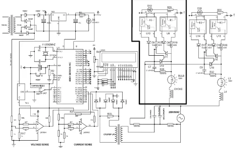
Fig 2. Schematic Diagram
VI.OPERATION EXPLANATION
CONNECTIONS
The output of power supply which is 5v is connected to the 40th pin of microcontroller and ground to the 20th pin or pin 20 of microcontroller. Port 0.0 of microcontroller is connected to Pin 2 of opto-isolator U10. Port 0.5 to 0.7 of microcontroller is connected to Pin 4, 5 and 6 of LCD display. Port 2.0 to 2.7 of microcontroller is connected to Pin 7 to 14 of data pins of LCD display. Port 3.1 of microcontroller is connected to output of the OP-Amp (A) LM339. Port 3.3 of microcontroller is connected to output of OP-Amp (B) LM339.
WORKING
ISSN (Print) : 2320 – 3765 ISSN (Online): 2278 – 8875
I
nternational
J
ournal of
A
dvanced
R
esearch in
E
lectrical,
E
lectronics and
I
nstrumentation
E
ngineering
(A High Impact Factor, Monthly, Peer Reviewed Journal)
Website: www.ijareeie.com
Vol. 7, Issue 5, May 2018
VII. ZERO CROSING VOLTAGE PULSES
In order to generate ZVP (Zero crossing Voltage Pulses) first we need to step down the supply voltage to 12 V and then it is converted into pulsating D.C. Then with the help of potential divider the voltage of 3 V is taken, which is given to a comparator. The comparator generates the zero crossing pulses by comparing this pulsating D.C with a constant D.C voltage of 0.6 V which is taken across a diode. Similarly, for ZVC (Zero crossing Current Pulses) the voltage drop proportional to the load current across a resistor is taken and is stepped up to generate ZVC.
Fig.3 Waveforms
CIRCUIT EXPLAINATION
The circuit consists of DC power supply unit, zero voltage crossing detectors, Micro-controller, LCD display, opto-isolator, SCR and Capacitor. The required DC power supply for Micro-controller and other peripherals is supplied by the DC power supply. For the calculation of the power factor by the Micro-controller we need digitized voltage and current signals. The voltage signal from the mains is taken and it is converted into pulsating DC by bridge rectifier and is given to a comparator which generates the digital voltage signal. Similarly, the current signal is converted into the voltage signal by taking the voltage drop of the load current across a resistor of 10 ohms. This A.C signal is again converted into the digital signal as done for the voltage signal. Then these digitized voltage and current signals are sent to the micro-controller. The micro-controller calculates the time difference between the zero crossing points of current and voltage, which is directly proportional to the power factor and it determines the range in which the power factor lies. Micro-controller sends information regarding time difference between current and voltage and power factor to the LCD display to display them, depending on the range it sends the signals to the opto-isolators that in turn switch ON back to back connected SCRs (power switches) to bring the capacitors in shunt across the load. Thus, the required numbers of capacitors are connected in parallel to the load as required. By this the power factor will be improved.
POWER FACTOR TEST LAYOUT
ISSN (Print) : 2320 – 3765 ISSN (Online): 2278 – 8875
I
nternational
J
ournal of
A
dvanced
R
esearch in
E
lectrical,
E
lectronics and
I
nstrumentation
E
ngineering
(A High Impact Factor, Monthly, Peer Reviewed Journal)
Website: www.ijareeie.com
Vol. 7, Issue 5, May 2018
to the inductive load that is the capacitor. So depending on the time difference required no. of SCR switches are switched, there by switching inductor till the voltage is corrected.
Fig.4 Power Factor Test Layout
VIII. CONCLUSION
It can be concluded that in long transmission lines connected to light load encounters voltage amplification (Ferranti effect), due to which the load connected at the receiving end may damage or become unstable. Power factor correction techniques can be applied to these transmission lines to make them stable and due to that the system becomes stable and efficiency of the system as well as the apparatus increases. These power factor correction technique includes the use of reactors which are connected in shunt with the transmission line at the receiving end and nullifies the effect of shunt capacitor. The use of microcontroller reduces the costs. Due to use of microcontroller, multiple parameters can be controlled and the use of extra hardwares such as timer, RAM, ROM and input output ports reduces. Care should be taken for over correction otherwise the voltage and current becomes more due to which the power system or machine becomes unstable. Flexible AC Transmission System is a new technology used to give an opportunity to increase stability, controllability and power transfer ability of AC transmission systems.
REFERENCES
[1] P. N. Enjeti and R martinez, “A high performance singlephase rectifier with input power factor correction,” IEEE Trans. Power Electron.vol.11, No.2, Mar.2003.pp 311-317.
[2] L. Gyugyi, R A . Otto and T.H. Putman, "Principles and Applications of Static, Thyristor-Controlled Shunt Compensators", IEEE Trans. on Power Apparatus and systems, vol. PAS-97, no. 5. pp. 1935-1945, Sept/Oct 1978
[3] N. G. Hingorani, Proceedings of the IEEE 76(4), 481 (1988).
[4] L. Gyugyi, IEE Proceedings C, Generation, Transmission and Distribution 139(4), 323 (1992). [5] orani, L. Gyugyi, Understanding FACTS: Concepts and Technology of Flexible AC
[6] H. Song, T. A. Johns, Flexible AC Transmission Systems (FACTS), IEE, London, 2000.S. Zelingher, B. Fardanesh, B. Shperling, S. Dave, L. Kovalsky, C. Schauder, A. Edris, Proc.
[7] S. N. Singh, International Journal of Energy Technology and Policy 4(3-4), 236 (2006). [8] L. Gyugyi, IEEE Transactions on Power Delivery 9(2), 904 (1994).
[9] L. Gyugyi, N. G. Hingorani, P. R. Nannery, N. Tai, CIGRE Paper 23-203, Paris (1990). [10] K. R. Padiyar, A. M. Kulkarni, Sãdhanã 22(6), 781 (1997).
[11] L. Gyugyi, IEEE Transactions on Industry Applications
[12] T. J. E. Miller, Reactive Power Control in Electric Systems, Wiley, New York, 1982. S. Jalali, I. Dobson, R. H. Lasseter, G. Venkataramanan, IEEE Transactions on Cicuits andSystems