Harmonic Elimination in Cascade Multilevel Inverter with Non
Equal Dc Sources Using Genetic and Differential Evolution
Algorithm
Sudhakar V. Pawar1, Mrs. Shimi S.L.2
M.E.(I&C) Student, Electrical Department, NITTTR, Chandigarh, India 1 Asst. Professor, Electrical Department, NITTTR, Chandigarh, India 2
Abstract
The elimination of harmonics in a cascaded multilevel inverter by considering the un-equality of separated dc sources by using Genetic and Differential Evolutionary Algorithm are compared. Solving a nonlinear transcendental equation set describing the harmonic-elimination problem with non-equal dc sources reaches the limitation of contemporary computer algebra software tools using the resultant method. The proposed approach in this paper can be applied to solve the problem in a simpler manner, even when the number of switching angles is increased and the determination of these angles using the resultant theory approach is not possible. Theoretical results are verified by simulations results for an 11-level H-bridge inverter. Results show that the proposed method does effectively eliminate a great number of specific harmonics, and the output voltage is resulted in low total harmonic distortion.
Keywords: Cascade multilevel inverter, Differential
Algorithm (DEA), Genetic Algorithm (GA), selective harmonic
elimination, unequal dc sources,
1. Introduction
Multilevel voltage-source inverters are a suitable configuration to reach high power ratings and high quality output waveforms besides reasonable dynamic responses. Among the different topologies for multilevel inverters, the cascaded multilevel inverter has received special attention due to its modularity and simplicity of control. The principle of operation of this inverter is usually based on synthesizing the desired output voltage waveform from several steps of voltage, which is typically obtained from dc voltage sources. There are different power circuit topologies for multilevel inverters. The most familiar power circuit topology for multilevel inverters is based on the cascade connection of an 's’ number of single-phase full-bridge inverters to generate a (2s + 1) number of levels. However, from the practical point of view, it is somehow difficult to keep equal the magnitude of separated dc sources (SDCSs) of different levels. This can be caused by the different charging and discharging time intervals of dc-side voltage sources. To control the output voltage and to eliminate the undesired harmonics in multilevel converters with equal dc voltages, various modulation methods such as sinusoidal pulse width
modulation (PWM) and space-vector PWM techniques are suggested.
However, PWM techniques are not able to eliminate lower order harmonics completely. Another approach is to choose the switching angles so that specific higher order harmonics such as the 5th, 7th, 11th, and 13th are suppressed in the output voltage of the inverter. This method is known as selective harmonic elimination (SHE) or programmed PWM techniques in technical literature. A fundamental issue associated with such method is to obtain the arithmetic solution of non-linear transcendental equations which contain trigonometric terms and naturally present multiple solutions. This set of nonlinear equations can be solved by iterative techniques such as the Newton– Raphson method. However, such techniques need a good initial guess which should be very close to the exact solution patterns. Furthermore, this method finds only one set of solutions depending on the initial guess. Therefore, the Newton–Raphson method is not feasible to solve the SHE problem for a large number of switching angles if good initial guesses are not available. A systematic approach to solve the SHE problem based on the mathematical theory of resultant, where transcendental equations that describe the SHE problem are converted into an equivalent set of polynomial equations and then the mathematical theory of resultant is utilized to find all possible sets of solutions for this equivalent problem.
three-phase applications. Reference presented modern stochastic search techniques based on particle swarm optimization (PSO) to deal with the problem for equal dc sources.
The DEA and PSO algorithm is developed to deal with the SHE problem with unequal dc sources while the number of switching angles is increased and the determination of these angles using conventional iterative methods as well as the resultant theory is not possible. In addition, for a low number of switching angles, the proposed DEA algorithm reduces the computational burden to find the optimal solution compared with iterative methods and the resultant theory approach. The proposed method solves the asymmetry of the transcendental equation set, which has to be solved in cascade multilevel inverters.
2. Cascaded H-Bridge Multilevel Inverter
A single-phase structure of an m-level cascaded inverter is illustrated in Figure 1. Each separate dc source (SDCS) is connected to a single-phase full-bridge, or H-bridge, inverter. Each inverter level can generate three different voltage outputs, +V
dc, 0, and –Vdc by
connecting the dc source to the ac output by different combinations of the four switches, S
1, S2, S3, and S4.
To obtain +V
dc, switches S1 and S4 are turned on,
whereas –V
dc can be obtained by turning on switches S2
and S
3. By turning on S1 and S2 or S3 and S4, the output
voltage is 0. The ac outputs of each of the different full-bridge inverter levels are connected in series such that the synthesized voltage waveform is the sum of the inverter outputs. The number of output phase voltage levels m in a cascade inverter is defined by m = 2s+1, where s is the number of separate dc sources. An example phase voltage waveform for an 11-level cascaded H-bridge inverter with 5 SDCSs and 5 full bridges is shown in Figure 2.3. The phase voltage v
an
= v
a1 + va2 + va3 + va4 + va5.+va4 + va5
.
.2.1 Advantages
• The number of possible output voltage levels is more than twice the number of dc sources (m = 2s + 1).
The series of H-bridges makes for modularized layout and packaging. This will enable the manufacturing process to be done more quickly and cheaply.
2.2 Disadvantages
Separate dc sources are required for each of the H-bridges. This will limit its application to products that already have multiple SDCSs readily available.
Fig.1Single-phase structure of a multilevel cascaded H-bridges
Fig.2 Output phase voltage waveform of an 11-level cascade inverter
with 5 separate dc sources
For a stepped waveform such as the one depicted in Fig. 2 with s steps, the Fourier Transform for this waveformfollows
Where n = 1, 3, 5, 7,...
3. Harmonic Elimination Control Technique
Using Evolutionary Algorithms using GA &
DEA
to its superior frequency spectra. It requires the solution of a set of transcendental nonlinear equations. Soft computing (SC) methods are extensively employed to solve this problem because of their effective global search ability. Genetic Algorithm (GA) and Differential evolution (DE) has surpassed most of the SC methods in diverse fields but it has never been utilized to solve this problem. In this work. GA and DE is utilized to solve the HEPWM problem for eleven level cascaded multilevel voltage source inverter (MVSI). Simulation results have shown that the discontinuities of the HEPWM angle trajectories are nullified and a wider over-modulation range has been covered, enhancing the utilization of DC link voltages and extending the application of HEPWM for high power applications.
3.1 Harmonic-Elimination Problem With Un-Equal
Dc Sources
By applying Fourier series analysis, the staircase
output voltageas shown in Figure 1. of multilevel
inverters with unequal sources can be described
as follows:
V(ωt)=
Where,
kiVdc is the i th
dc voltage,
Vdc is the nominal dc voltage,
θ1–θmis the switching angles
θ1–θmmust satisfy the following condition:
The number of harmonics which can be eliminated from the output voltage of the inverter is s-1. For example, to eliminatethe fifth-order harmonic for a five-level inverter, equation set (3.1) must be satisfied. Note that the elimination of triplen harmonicsfor the three-phase power system applications is not necessary, because these harmonics are automatically eliminated from the line–line voltage
(3.1)
In Eqn. (2.3), modulation index M is defined as M =
V1/sVdc andV1 is the fundamental of the required voltage.
The fitness function is given by
f = 100 x
(3.2)
3.2 Formulating the problem
The step- by- step procedure to solve the SHE problem with unequal dc sources using GA is
as follows.
i) Get the data for the system. At the first step, the required parameters of the algorithm such as population size, modulation index (M), Nominal Voltage, Number of Inverter level, max iteration number are determined.
ii) Random population generation.
iii) Fitness function – the fitness evaluation evaluate the population using the fitness function given by equation (3.2).
iv) Parent Selection – Best parents of generation are selected based on the rouleete. Wheel selection for creating next generation.
v) Crossover – the crossover operator creates the two new child vector by mating the two best parents using arithmetic crossover method. vi) Mutation – the mutation operator mutates a child
by changing any of it’s genes.
vii) Survival Selection – the survival selection operator chooses the vectors that are going to compose the population in the next generation.
The step- by- step procedure to solve the SHE problem with unequal dc sources using DEA is
as follows.
i) Get the data for the system similar to GA.
ii) Initialization – to create an initial population of candidate solutions by assigning random values to each decision parameter of each individual of the population.
iii) Mutation – the mutant vector is generated according to equation 3.3
(3.3 )
iv) Crossover – The crossover operator creates the trial vectors, which are use in the selection process. The trial vector is a combination of a mutant vector and a parent (target) vector based on different distributions.
v) Fitness Evaluation –The fitness evaluation
f = 100x ( 3.4) vi) Selection – The selection operator chooses the vectors that are going to compose the population in the next generation. This operator compares the fitness of the trial vector and fitness of the parent vector, and select the one that performs better (Minimum fitness value).
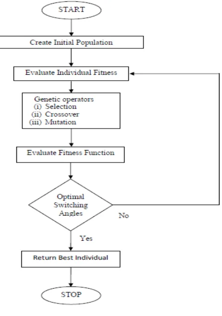
4. Methodology
Fig. 3 Flowchart of Methodology
4.1 Genetic Algorithm
Fig. 4 Flowchart of GA
4.3 Differential Evolution Algorithm
Fig. 5 Flowchart of DEA
4.3.1 Steps of Differential Evolution
The main steps of the DE algorithm are given below: • Initialization
• Mutation
• Crossover
• Selection
Mutation
For each target vector xi,G,i= 1,2,3,…..,NP, a mutant
vector is produced by withrandom indexes r1, r2, r3 {1,2,….,NP}, integer,
mutually different and F > 0. The mutation factor F is a constant from [0,2] which controls the amplification of the differential variation
. Crossover
In order to increase the diversity of the parameter vectors, crossover is introduced. To this end¸ the trial vector:
ui,G+1 = (u1i,G+1, u2i,G+1,….,uDi,G+1)
is formed, where
=
In equation of is the jth evaluation of a uniform
random number generator with outcome [0,1]. is the crossover constant [0,1] which has to be determined by the user. is a randomly chosen index (1,2,…, D) which ensure that ui,G+1gets at least one parameter from
vi,G+1.
Selection
To decide whether or not it should become a member of generation G+1, the trial vector ui,G+1 is compared to the
target vector xi,G using the greedy criterion. If vector ui,G+1
yields a smaller cost function value than xi,G, then xi,G+1 is
set to ui,G+1; otherwise, the old value xi,G is retained.
5. Result
Table 5.1: Result of GA
Table 5.1: Result of DEA
Fig. 6 Output voltage waveform result of GA of MI=0.7 Modu
lation
index Switching Angle
Best fitness
value
THD
0.47 37.677 52.9404 67.9967 87.2381 88.4476 2.6361 3.634
9
0.7 27.736 45.1437 52.7554 67.0311 73.9256 1.8798 2.978
5
0.9 7.3371 24.1424 36.3949 51.1229 67.8242 1.7717 2.627
8
1.075 4.5004 12.0497 21.3627 29.8443 44.9095 1.3775 2.413
7
Modu lation
index Switching Angle
Best fitness
value
THD
0.47 37.713 52.8114 68.1956 86.2504 89.3960 2.5298 3.6349
0.7 29.365 49.2390 49.2436 66.8150 72.4167 0.7940 2.9785
0.9 7.2486 24.1497 36.2570 51.0896 67.7601 1.7239 2.6268
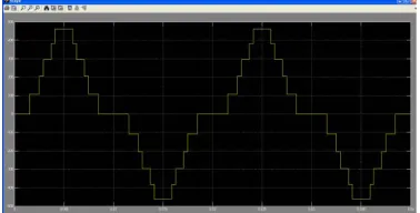
Fig. 7 Output voltage waveform result of DEA of MI=0.7
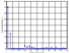
Fig. 8 FFT of Output voltage waveform result of GA of MI=0.7
0 5 10 15 20 25 30 35 40 45 50 0 10 20 30 40 50 60 70 80 P eak M agni tude, V
Order of harmonic
Fig. 9 FFT of Output voltage waveform result of DEA of MI=0.7
6. Conclusion
This paper has outlined the approach to use Differential Evolution search method to determine the switching angles of multilevel inverters. It has been shown that the method can accurately compute the multilevel inverters switching angles without having to make “ correct” guesses on the initial values of the switching angles. Simulations are carried out to verify the algorithm when applied to a single phase inverter. The results are found to be in close agreement with the common knowledge of multilevel inverter.
A method to generate optimal switching angles in order to eliminate a certain order of harmonics is introduced in this paper. A cost function describing the selective harmonic elimination in cascaded multilevel inverter with non-equal dc sources is formulated and addressed. The algorithm was developed using MATLAB software and is run for a
number of times independently to ensure the feasibility and the quality of the solution
.
GA and DEA algorithm solve the non linear transcendent equations with a much simpler formulations. Also it can be used for any number of voltage levels without complex analytical calculations.
References
[1] H. Taghizadeh and M. TarafdarHagh., “Harmonic Elimination of Cascade Multilevel Inverters with Non-equal dc Sources Using Particle Swarm Optimization”, IEEE Transactions on Industrial Electronics, Vol. 57, No. 11, pp.3678-3684, November 2010..
[2] José Rodríguez, Jih-Sheng Lai, and Fang ZhengPeng., “Multilevel Inverters: A Survey of Topologies, Controls, and Applications”, IEEE Transactions on Industrial Electronics, Vol. 49, No. 4, pp.724-738, August 2002.
[3] SumanDebnath and Rup Narayan Ray., “Harmonic Elimination in Multilevel Inverter usingGA and PSO:A Comparison”, IEEE Students Conference on Electrical, Electronics and Computer Science,Agartala – 799055, India, Vol. 9, No. 12, 2012.
[4] FaeteFilho, HelderZandonadi Maia, Tiago H. A. Mateus, BurakOzpineci, Leon M. Tolbert, and João O. P. Pinto., “Adaptive Selective Harmonic Minimization Based onANNs for Cascade Multilevel Inverters with Varying dc Sources”, IEEE Transactions on Industrial Electronics, Vol. 60, No. 5, pp.1955-1962, May 2013 [5] Mohamed S. A. Dahidah, and Vassilios G. Agelidis., “Hybrid
Genetic Algorithm for SelectiveHarmonic Elimination Control of a MultilevelInverter with Non-Equal DC Sources”, IEEE, Transitions on Industrial Electronics Drives, Vol. 5, No. 05, pp.1205-1210, 2005
[6] N. Bahari, Z. Salam, Taufik., “Application of Differential Evolution to Determine the HEPWM Angles of a Three Phase Voltage Source Inverter”, IEEE, Transitions on Power Electronics and Drives Group,Vol. 2, No. 10, pp. 2683-2688, 2010
[7] K. Haghdar, H. A. Shayanfar, M. H. ShahidiAlavi.,“Selective Harmonics Elimination of Multi Level Inverters via Methods of GPS, SA and GA”, IEEE Transition on Center of Excellence for Power System Operation and Automation, Vol. 1, No. 11, 2011. [8] AyoubKavousi, BehroozVahidi, Reza Salehi, Mohammad
KazemBakhshizadeh, NaeemFarokhnia, and S. Hamid Fathi., “Application of the Bee Algorithm for Selective Harmonic Elimination Strategy in Multilevel Inverters”, IEEE Transactions on Power Electronics, Vol. 27, No. 4, pp.1689-1696, April 2012 [9] MehrdadTarafdarHagh, Hassan Taghizadeh, and KavehRazi.,
“Harmonic Minimization in Multilevel Inverters Using Modified Species-Based Particle Swarm Optimization”, IEEE Transactions on Power Electronics, Vol. 24, No. 10, pp.2259-2267, October 2009
[10] F. J. T. Filho, Leon M. Tolbert, and BurakOzpineci., “Real Time Selective Harmonic Minimization for Multilevel Inverters Using Genetic Algorithm and Artificial Neural Network Angle Generation”,IEEE 7thInternational Power Electronics and Motion
Control Conference, Harbin, China, Vol. 8, No. 11, pp.895-899, June 2012.
[11] NaeemFarokhnia, HadiVadizadeh, Seyyed Hamid Fathi, and FaribaAnvariasl, “Calculating the Formula of Line-Voltage THD in Multilevel Inverter With Unequal DC Sources”, IEEE Transactions on Industrial Electronics, Vol. 58, No. 8, pp.3359- 3371, August 2011.
[12] A. Ebrahimi, N. Farokhnia, and S. H. Fathi., “A Hybrid Approach for Solving NonlinearEquations of SHEPWM in Multilevel
0 5 10 15 20 25 30 35 40 45 50 0 50 100 150 200 250 300 350 400 P eak M agni tude, V
Inverters”, IEEE, Transition on Graduate Student Member, Vol. 9, No. 12, pp.1962- 1967, 2012
[13] P. MaruthuPandi,and N.Devarajan., “Estimation of Optimized Power Quality In Micro Controller Based Cascaded Multilevel Inverter”, IEEE, Irkutsk , Russia, Vol. 8,No. 10, pp.671-676, July 2010
[14] Ahmadi, D. and Jin Wang., “ Full Study of Precise and Practical Harmonic Elimination Method for Multilevel Inverters”, IEEE, transition on Applied Power Electronics Conference and Exposition, Washington DC, Vol. 1, No. 10, pp. 871-876, Feb. 2009
[15] Song Li,and Manyuan Ye, “Simulation study of harmonicelimination technology for multilevelinverters”, IEEE, Electronic, Mechanical Engineering and Information Technology, International Conference, Harbin, China, Vol. 5, No. 01, pp 2738-2741, Aug. 2011
[16] Salam, Z.,Amjad, A.M., and Majed, A., “Using Differential Evolution to Solvethe Harmonic Elimination PulseWidth Modulation for Five LevelCascaded Multilevel Voltage SourceInverter”, IEEE, Artificial Intelligence, Modelling and Simulation, International Conference, Kota Kinabalu, Vol. 01, No. 04, pp. 43-48, Dec. 2013