Design and Implementation of UWB Receiver
Rahul Malhotra, Tanvi
Deptt. of Electronics and Communication Engineering,.Bhai Maha Singh College of Engineering, Muktsar, Punjab
Abstract
—
Wireless technology has given us a convenient way to transfer information from one point to other anywhere in the world. The last two decades have been the most dynamic in the history of wireless communication. The recent popularity of wireless networks results in many additional requirements of the system, especially the need of high data rates, demand for high quality multimedia services and very important, the requirement of greater bandwidth. The Ultra WideBand (UWB) radio communication is providing new direction to utilize the radio spectrum for the broadband short-range radio communications. The key feature that makes UWB technology unique is low cost transceiver design. In this paper UWB receiver is designed and then some characteristics such as Bit Error Rate, Delay, Load etc. are implemented by using MATLAB and OPNET. Network cables such as TR4 (Token Ring 4Mbps) and TR16 (Token Ring 16Mbps) are used to test the delay factor in UWB receiver architecture in both cases.Keywords - UWB Technology, UWB receiver, Frequency Domain Analysis, BER, MATLAB, OPNET.
I. INTRODUCTION
UWB is a Radio Frequency (RF) technology [6], [7] that transmits binary data, using low energy and extremely short duration impulses or bursts (in the order of picoseconds) over a wide spectrum of frequencies. It delivers data over 15 to 100 meters and does not require a dedicated radio frequency, so is also known as carrier-free, impulse or base-band radio. Basically, Ultra-Wideband (UWB) is a high data rate, low power short-range wireless technology that is generating a lot of interest in the research community and the industry, as a high-speed alternative to existing wireless technologies such as IEEE 802.11 WLAN, HomeRF, and Hiper LANs. The main advantage of UWB technology is low cost transceiver design. The major challenges in Ultra Wideband Communication Receivers [8] are high speed, high dynamic range of ADC and Wideband Low Noise amplifier. Signals, once generated, transmitted, propagated, must be received in order to be understood. The main function of any receiver is to capture signal energy with the antenna, extract the information from the signal and finally present that information. The receiver collects the electromagnetic energy from the antenna, takes the extremely weak signal, reconstructs the pulse shape, and maps it to the appropriate symbols and then to the binary stream. The art is in taking the signal in and efficiently recovering the conveyed information. In this article, approach is used to process received signals in frequency domain for designing UWB communication receiver. The key feature is to extract the frequency components of the received signal and also to analyse the signal processing in frequency domain.
II. SIGNALANALYSISINFREQUENCYDOMAIN Signal processing [13] involves techniques that improve our understanding of information contained in received data. Normally, when a signal is measured with an oscilloscope, it
is viewed in the time domain (vertical axis is amplitude or voltage and the horizontal axis is time). For many signals, this is the most logical and intuitive way to view them. The time domain representation of the signal is not sufficient for signal analysis. In frequency domain representation, the variable plotted on the X-axis is frequency “f” rather than “t”. The signal represented in the frequency domain is called as the line spectrum. The line spectrum consists of two graphs namely, Amplitude Spectrum (graph of amplitude versus frequency) and Phase Spectrum (graph of phase versus frequency). In time domain, it cannot be known that what frequency components are present and in what proportion they have been mixed in order to obtain the particular shape of the signal.
The main tools for frequency domain analysis are Laplace Transform, Discrete Time Fourier Transform (DTFT), its generalization, z-Transform and especially Discrete Fourier Transform (DFT). The Fourier transform transforms a time domain signal into a frequency domain representation of that signal. This means that it generates a description of the distribution of the energy in the signal as a function of frequency. This is normally displayed as a plot of frequency (x-axis) against amplitude (y-axis) called a spectrum. The
Fourier Transform of a signal x(t) is defined as follows:-
A continuous-time periodic signal with a period Tp can be
expressed as:-
and
where ck represents a spectral component of a signal and F0=
1/Tp is fundamental frequency of the desired signal x(t). By
using the properties of sinusoidal properties the following relation can be obtained given below:-
Using the formulas of Laplace transform for cosine and sine function, one more relation can be derived given as follows:-
III.CONCEPT OF SAMPLING THEOREM
Sampling is a process in which a signal is converted into numeric sequence. The statement of the sampling theorem tells that:-
“A band limited continuous time signal may be completely represented in its samples and recovered back from the knowledge of its samples, if the sampling frequency is fs≥ 2fc,
where fs is the sampling frequency and fc is the highest
frequency contained in the signal.”
The Nyquist sampling theorem provides a prescription for the nominal sampling interval required to avoid aliasing. When the sampling rate becomes exactly equal to 2fc samples per
second, then it is called Nyquist rate. It can be also named as Maximum Sampling Rate which is given by
fs 2fc
Similar maximum sampling interval is called Nyquist Interval. It is given by
Ts = sec.
Hence the concept of sampling theorem and its property can be used to increase the sampling rate of received signal.
IV.FILTER DESIGN USING FREQUENCY DOMAIN APPROACH
The world of filter design [10] is often thought of as black magic because of the myriad of configurations, unique
terminology, and complex equations. For designing UWB
receiver, it must consist of filter whose output can be calculated with the help of frequency domain analysis. Coefficient ck can be obtained by sampling the outputs of
analog filters with transfer functions of and
The filter with a transfer function of can be implemented using an LC resonator, and the factor of .s. is a
differentiator. Thus by using signal analysis in frequency domain, the outputs of filter with transfer function can be obtained given below:-
Imaginary Axis =
Real Axis =
The main function of filter bank is to spectral component of the received signal.
Figure 1:- Filter Bank
Hence the filter can be designed with the help of transfer function. In case of UWB receiver Biquad Filter plays an important role. A biquad filter is a type of linear filter that
implements a transfer function that is the ratio of two quadratic functions. The name biquad is short for biquadratic. Biquad filter and its voltage response are shown below:-
With the help of these two equations Biquad filter is designed using circuit simulation tool.
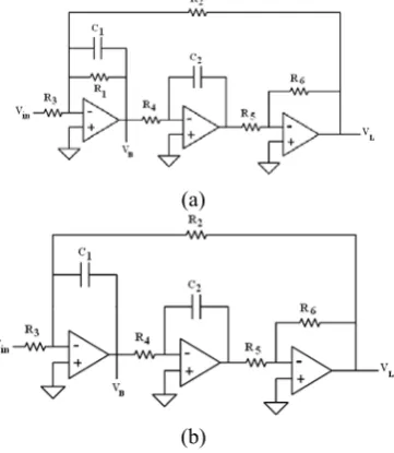
Figure 2:- Biquad filter using circuit simulation tool
Comparing above equations, it seems to conclude that real spectral term can be found from Band Pass Filter output, whereas imaginary spectrum can be found by Biquad filter. The biquad configuration is a useful circuit for producing band pass and low-pass responses, which require high Q-factor values. Other problem is to make a Q Q-factor infinite. It can be achieved by eliminating 1/Q feedback path. Operational amplifiers can be used to realize a linear system with an arbitrary biquadratic transfer function. This function is the ratio of two quadratic expressions in s. The figure shows Biquad filter using three Op-Amps.
It consists of leaky integrator, an integrator and summing amplifier. The Biquad topology is suited to operation from a single supply. Current feedback amplifiers cannot be used, because a capacitor is connected from the op amp output to inverting input. This filter offers complete and independent control over gain and frequency. Signal input is at one place, and the output is taken from different places. The Biquad filter has the unique characteristic of producing two polarities of low pass output.
(a)
(b)
This part shows the filter design for UWB Receiver using OP-AMP. A frequency domain sampler consists of multiple filter banks followed by analog to digital convertor (ADC). Each filter bank (f0, f1,………, fn-1) captures the spectral
component of the frequency of received signal. Each filter bank needs two ADCs.
Figure 4:- Frequency Domain Sampler
V. RECONSTRUCTION OF SIGNAL IN TIME DOMAIN
It is possible to reconstruct a sampled signal in time domain from spectral components obtained from frequency domain sampler. This can be done using Inverse Fast Fourier Transform (IFFT).
VI.UWBRECEIVER USING FREQUENCY DOMAIN APPROACH
The major challenges in Ultra Wideband Communication Receivers are high speed, high dynamic range of ADC [14] and Wideband Low Noise amplifier. To meet up the challenges, RAKE receivers are necessary to be used to exploit multipath diversity. Use of RAKE receiver further reduces the delay and enhances the speed. As mentioned above, Digital Signal Processor requires the synchronization with Analog to Digital Converter, at least as fast as comparable to its Nyquist rate. Due to its simple hardware and more accurate ranging, Ultra Wideband receivers [1], [3], [4], [5] are preferable. UWB Receiver contains multiple narrowband Low Noise Amplifiers (LNAs), a Frequency Domain Sampler, an Energy Harvester block and Decision section. This designed UWB receiver is used to compare with conventional analog receivers. Given below is the block diagram of proposed UWB receiver.
Figure 5:- Designed UWB Receiver Architecture
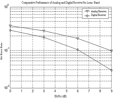
LNAs are usually placed at the front-end of a receiver system, immediately following the antenna. A band pass filter may be required in front of it if there are many adjacent interfering bands leaking through the antenna, but this filter generally degrades the noise performance of the system. The purpose of an LNA [2] is to boost the desired signal power while adding as little noise and distortion as possible so that retrieval of this signal is possible in the later stages in the system. In this paper, one LNA is applied to frequency domain sampler. The second section is energy harvester. The main function of energy harvester is that it collects the energy dispersed on the multipath. A new template signal based on the resolved multipath signals is generated and is correlated with the received signal to collect the energy on multipath. The results are given as shown below. The bit-error-rate performance of a receiver is a figure of merit that allows different designs to be compared in a fair manner. Performing the BER (bit-error-rate) testing with Matlab is very simple. The upper curve represents BER performance of analog receiver and lower curve shows the BER performance of digital UWB receiver.
Figure 6:- Comparison of Bit Error Rate (BER) for Analog and Digital UWB receiver for Upper band
Figure:-7 Comparison of Bit Error Rate (BER) for Analog and Digital UWB receiver for Upper band
VII. UWBRECEIVER DESIGN USING OPNET
is used to design Ultra Wideband Receiver which is connected to some different node stations and central station.
Figure 8:- Network Architecture for proposed UWB Receiver
Above proposed network consists of five node stations naming node_1, node_2, node_3, node_4 and node_5, one switch, one proposed UWB digital receiver. UWB Receiver taken in this network is just like a packet analyzer running over Ethernet connection. Two type of cables are used for connection:- TR4 (Token Ring 4Mbps) and TR16 (Token Ring 16Mbps). The performance of both connections is calculated. Protocols used for UWB receiver are IP and IEEE 802.3 (Ethernet, Fast Ethernet and Gigabit Ethernet). Network consists of IP Attribute Configuration also which defines details for protocols supported at the IP layer. IP ping parameters defines different ping settings that individual host in the given network can use to determine the connectivity to the specified destination.
At the centre of the proposed network, Ethernet Switch is used which represents a switch supporting up to 16 Ethernet Interfaces. The switch implements the spanning algorithms in order to ensure loop free network topology. Switch communicates with given five nodes (node_1, node_2, node_3, node_4 and node_5) and also with UWB Receiver by sending Bridge Protocol Data Units (BPDU’s). Packets are received and processed by the switch based on the proposed configuration. Protocols suitable for switch are Spanning Tree Bridge Protocol (IEEE 802.1D) and Ethernet (IEEE 802.3). This switch is connected to the same type i.e. Token Ring to Token ring. Blue line shown in the given network architecture represents Token Ring 4Mbps (TR4) and Token Ring 16Mbps (TR16). These connect two token devices to form a ring at 4Mbps or 16Mbps. Data rates of both TR4 and TR16 are 4Mbps and 16Mbps.
Node_1, Node_2, Node_3, Node_4 and Node_5 represents ethernet stations which are connected individually to switch along with UWB receiver. The main function of these nodes is to handle transmission requests from higher layers, encapsulate packets into frames and send the frames to the other side of interface. The speed at which the MAC layer operates is governed by the date rate of the connected link i.e. 4Mbps in case of TR4 and 16Mbps in case of TR16. Supported protocol used is IEEE 802.3. Attribute like Application Traffic Generation Rate specifies the mean rate (in packets/sec) at which packets are generated by the given nodes. The packets inter-arrival times are exponentially
distributed. Given below are the simulation results of characteristics of all five nodes and UWB receiver.
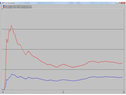
Figure 9:- Traffic received and forwarded through Switch
Switch is used at the centre of the give network. Figure shows time average of traffic received and forwarded in packets/sec by ethernet switch for network1 using network cable TR4 having data rate of 4Mbps. It can be seen that at the start of the simulation process, rate of traffic forwarding is higher than that of traffic receiving through ethernet switch.
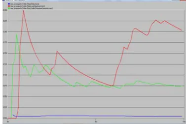
Figure 10:- Delay, Load and Traffic received through token ring of node_1 using TR4 network cable.
Above figure shows time average of delay (in secs), load and traffic received in packets/sec in token ring by node_1 for network1 using network cable TR4 which concludes that delay is almost negligible due to small network and load is much heavier than that of traffic received.
Figure11:- Delay, Load and Traffic received through token ring of node_2 using TR4 network cable.
for network1 using network cable TR4 which concludes that delay in this case also is negligible due to small network but here traffic received is very much higher than that of node_1.
Figure 12:- Delay, Load and Traffic received through token ring of node_3 using TR4 network cable.
Above figure shows time average of delay (in secs), load in packets and traffic received in packets/sec in token ring by node_3 for network1 using network cable TR4 which concludes that delay is almost negligible due to small network and load is much heavier as compared to node_1 and node_2.
Figure 13:- Delay, Load and Traffic received through token ring of node_4 using TR4 network cable.
Load is much heavier than traffic received in this case because the some of the packets lost during switching sh13.own in above figure
Figure14:- Delay, Load and Traffic received through token ring of node_5 using TR4 network cable.
From figure 14, it is observed that the node_5 receives more traffic than that of node_4 and load of node_4 is much heavier than node_5. One thing is noted that in all five node stations, delay is negligible because the network architecture designed is very small. Here also TR4 network cable is considered.
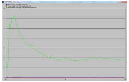
Figure 15:- Delay, Load and Traffic received through token ring of UWB Receiver using TR4 network cable.
The time average of delay, load and traffic received by UWB receiver for network1 in token ring is calculated and thus it is concluded that traffic is received by UWB receiver from switch and all other nodes with high proportion at the start of simulation by using TR4 network cable at 4Mbps.
Figure 16:- Utilization of UWB Receiver using TR16 network cable
Figure 17:- Traffic received and forwarded through Switch
Figure shows time average of traffic received and forwarded in packets/sec by ethernet switch for network1 using network cable TR16 having data rate of 16Mbps. It can be seen that at the start of the simulation process, rate of traffic forwarding is higher than that of traffic receiving through ethernet switch.
Figure18:- Delay, Load and Traffic received through token ring of node_1 using Token Ring 16Mbps network cable.
Above figure shows time average of delay (in secs), load and traffic received in packets/sec in token ring by node_1 for network1 using network cable TR16 which concludes that delay is almost negligible due to small network and load is much heavier than that of traffic received.
Figure19:- Delay, Load and Traffic received through token ring of node_2 using Token Ring 16Mbps network cable.
Above figure shows time average of delay (in secs), load and traffic received in packets/sec in token ring by node_2 for
network1 using network cable TR16 which concludes that delay in this case also is negligible due to small network but here traffic received is very much higher than that of node_1.
Figure 20:- Delay, Load and Traffic received through token ring of node_3 using Token Ring 16Mbps network cable.
Above figure shows time average of delay (in secs), load in packets and traffic received in packets/sec in token ring by node_3 for network1 using network cable TR16 which concludes that delay is almost negligible due to small network and load is much heavier as compared to node_1 and node_2.
Figure21:- Delay, Load and Traffic received through token ring of node_4 using Token Ring 16Mbps network cable.
There is very important point to note in all cases that the delay section is very less in case of all stations. This delay becomes a key factor to compare the performance of TR4 and TR16 network cables.
From figure 21 and 22 it is observed that the node_5 receives more traffic than that of node_4 and load of node_4 is much heavier than node_5. One thing is noted that in all five node stations, delay is negligible because the network architecture designed is very small. Here also TR16 network cable is considered.
Figure 23:- Delay, Load and Traffic received through token ring of node_2
The time average of delay, load and traffic received by UWB receiver for network1 in token ring is calculated and thus it is concluded that traffic is received by UWB receiver from switch and all other nodes with high proportion at the start of simulation by using TR16 network cable at 4Mbps.
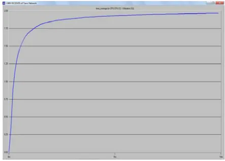
Figure 24:- Utilization of UWB Receiver using TR16 network cable
It represents time average of utilization of network resources by UWB Receiver. The graph abruptly increases at the start of simulation but becomes stable as the simulation time increases.
Hence by using above two network cables the delay, load, traffic received parameters are compared which are almost same but the delay factor is different in both cases. In latter section the performance of TR4 and TR16 network cables are compared in terms of delay factor and hence judged which one is better.
VIII.COMPARISON OF TR4 AND TR16NETWORK CABLES
USED IN UWBRECEIVER ARCHITECTURE
Token Ring (TR) uses a ring topology whereby the data is sent from one machine to the next and so on around the ring until it ends up back where it started. It also uses a token passing protocol which means that a machine can only use the network when it has control of the Token; this ensures that there are no collisions because only one machine can use the network at any given time. Two type of cables are used
for connection:- TR4 (Token Ring 4Mbps) and TR16 (Token Ring 16Mbps). The performance of both connections is calculated. Protocols used for UWB receiver are IP and IEEE 802.3 (Ethernet, Fast Ethernet and Gigabit Ethernet). Here delay parameter of all five nodes (node_1, node_2, node_3, node_4 and node_5) and for UWB receiver are calculated and compared. Two scenarios are taken named as scenario 1and scenario2. Blue curve in all results show the delay performance in case when TR4 network cable is used in the proposed network architecture and red curve shows the delay performance in case when TR16 network cable is used.
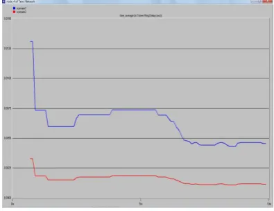
Figure 25:- Network Delay for node_1 for different types of cables (TR4 & TR16).
It is concluded from the above view that network delay for node_1 in case of scenario1 is seen to be .00350 when using TR4 network cable at simulation time of 2m while for scenario2 it comes out to be less than .001 at same simulation time. Hence network delay of scenario2 (using TR16 network cable) is less as compared to scenario1. The delay of node_2 using network cable TR16 is less as compared to that using TR4 network cable.
Figure 26:- Network Delay for node_2 for different types of cables (TR4 and TR16).
Figure 28:- Network Delay for node_4 for different types of cables (TR4 and TR16).
Figure 29:- Network Delay for node_5 for different types of cables (TR4 and TR16).
Hence from figure 27, 28, 29 and 30, it is clearly seen that delay parameter of all node stations and UWB receiver using TR16 is less in case of using network cable TR4
Figure 30:- Network Delay for UWB Receiver for different types of cables (TR4 and TR16).
IX.CONCLUSION
The Ultra WideBand (UWB) radio communication is providing new direction to utilize the radio spectrum for the broadband short-range radio communications and thus offering a clear vision to the development of wireless networks The recent popularity of wireless networks results in many additional requirements of the system, especially the need of high data rates, demand for high quality multimedia services and very important, the requirement of greater bandwidth and low cost transceiver design. Here UWB receiver is designed and then its characteristics are implemented using MATLAB and OPNET. The comparison of BER for analog and digital receiver has been carried out in MATLAB. The simulation result shows the better performance of digital receiver as compared to analog receiver for both upper band and lower band. Further
another UWB receiver is designed using two different types of network medium i.e. connecting cables of 4Mbps and 16Mbps. The comparative results show the better performance when 16Mbps cable was used. From both simulation, it is evident that digital receiver with higher bandwidth outperforms analog as well as digital receiver with less bandwidth spectrum.
REFERENCES
[1] D. Barras, F. Ellinger, and H. Jäckel, “A comparison between ultra-wide-band and narrow-band transceivers, “TRLabs/IEEE Wireless
2002, pp. 211–214, Jul. 2002.
[2] Chih-Fan Liao and Shen-Iuan Lui, “A Broadband Noise-Canceling CMOS LNA for 3.1-10.6 GHz UWB Receiver”, in Proceedings of the IEEE 2005 Custom Integrated Circuits Conference, pp. 161-164, September 2005.
[3] J.D. Choi and W.E. Stark “ Performance of Ultra-Wideband
Communications with Suboptimal Receiver in Multipath Channels”, in IEEE Journal on Selected areas in Communication, vol. 20, no. 9, pp. 1754-1766, December 2002.
[4] L. Feng and W. Namgoong “An Oversampled Channelized UWB Receiver with Transmitted Reference Modulation”, in IEEE Transactions on Wireless Communications, vol. 5, no. 6, pp. 1497-1505, June 2006.
[5] J.R. Fernandes and D. Wentzloff “Recent advances in IR-UWB transceivers: An overview”, in Proceedings of 2010 IEEE International Symposium on Circuits and Systems (ISCAS),pp.
3284-3287, June 2010.
[6] Foerster, J., Green, E., Somayazulu, S. and Leeper, D., “ Ultra-Wideband Technology for Short or Medium-Range Wireless Communications”, Intel Technology Journal, Q2, 2001.
[7] R. Fontana, A. Ameti, E. Richley, L. Beard and D. Guy “Recent advances in ultra- wide-band communications systems,” in Proc. IEEE Conf. Ultra Wide-Band Syst. Technol., , May 2002, pp. 271– 275.
[8] R. J. Fontana “Recent System Applications of Short- Pulse Ultra-Wideband Technology” in IEEE Transactions on Microwave Theory and Techniques, vol. 52, no. 9, pp. 2087-2104, September 2004. [9] E.R. Green and S. Roy “System Architectures for High-rate
Ultra-wideband Communication Systems: A Review of Recent Developments”, Intel Labs, 2004.
[10] C.L. Hsu, F.C. Hsu and J.T. Kuo “Microstrip bandpass filters for ultra-wideband (UWB) wireless communications,” in 2005 IEEE MTISInternational Microwave Symposium Dig., WE2F-2, June 2005. [11] S.I. Husain and J. Choi “Single Correlator Based UWB Receiver
Implementation through Channel Shortening Equalizer” in Asia-Pacific Conference on Communications, pp. 610-614, 3 - 5 October
2005.
[12] I.Y. Immoreev “Ultra Wideband Radio Systems: Their Peculiarities and Capabilities”,Electromagnetic Phenomena, vol.7, no. 1, 2007.
[13] M. Kumar, A. Basu and S.K. Koul “ A novel scheme for generating and transmitting UWB signals," in Journal of Communication and Computer, ISSN 1548-7709, USA, Vol. 7, No.4 (Serial No.65), April 2010.
[14] P.P. Newaskar, R. Blazquez and A.P. Chandrakasan “A/D precision requirements for an ultra-wideband radio receiver,” in IEEE Workshop on Signal Processing Systems., vol. 1, pp. 270–275, October 2002.
[15] R.C. Qiu “A Study of the Ultra-Wideband Wireless Propagation Channel and Optimum UWB Receiver Design”, in IEEE Journal on Selected Areas in Communications, vol.20, no. 9, pp. 1628-1637, December 2002.
[16] R.A. Scholtz, R.Weaver, E. Homier, J. Lee, P. Hilmes, A. Taha and R. Wilson “ UWB Radio Deployment Challenges”, in Proceedings of IEEE PIMRC 2000, vol. 1, pp. 620-625, September 2000.
[17] K. Siwiak “ Ultra-wideband radio: Introducing new technology”, in
Proc. IEEE Vehicular Technology Conf., vol. 2, pp. 1088-1093, May
2001.