ARM PROCESSOR BASED COLLISION AVOIDANCE AND BLIND SPOT DETECTION
TECHNIQUES
Amar Birajdar1*, Sanket Thalkari2, Shrikant Kumbhar3
123*SENSE Department, VIT University Chennai -600127 Tamil Nadu
Correspondence Author:[email protected]
Keywords:Blind spot, Sensors, Detection, Automobile, Nuvotn.
Abstract
This paper presents ultrasonic and infrared sensor based distance measurement techniques for automotive applications, to avoid the collision and detection of blind spot. Ultrasonic sensors are well-accepted technology for distance sensing applications, they provides accurate distance measurement. Infrared sensors are also included to detect the presence or absence of object. This system provides alert to driver when object/ vehicles have detected, which is closer to predefined level and also necessary action will be taken to avoid collision. ARM Nuvotn processor is used in this design to perform complex task with effective distance sensing as well as provides alert to the driver. This is low cost design intended for automobile safety to avoid collisions t he proposed systems detect blind spots areas and it avoids collisions. The feasibility of this approach and its robustness against environmental conditions are tested by means of various experimental testings performance.
Introduction
This technology is designed to alert the driver, blind spot object detection ARM controller based systems are designed to alert the driver to the presence of other vehicles that may be in the blind spot areas of adjacent lanes of traffic. Blind spots are the areas on both sides and rearward of a vehicle not visible within the rear view or door mirrors blind spot object detection systems can be as simple as using a convex mirror as part of the door mirrors, or it may be front or rear distance measurement based electronic system[1]. Usually it will respond when the driver puts on your turn signal, if it detects something in the way below to pre-set distance value, it may flash a light in your mirror LED as display will glows as well as it will turn on sound alarm on mirror infrared sensors are kept This is more of a short-range detection system and for front and rear distance measurement ultrasonic sensors are used for long range distance measurements [1].
System design
As shown in fig 1 ultrasonic sensor front and rear side are interfaced to the ARM Nuvotn boards. Infrared sensors which are placed on mirror are also interfaced to the ARM processor. For driver indication display as well as buzzer systems are interfaced with the processor it will indicate alert when another vehicle is detected closer. It will full assist driver for safe driving.
Fig.1 Block diagram system design
Ultrasonic sensor
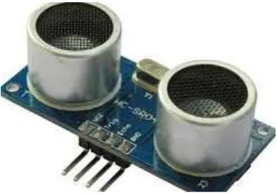
HCSR04 ultrasonic sensor module [5].following are some formula which are actually used for calculating distance by using these expression we can get correct value .While programming module we have to put these formula in this program.
1. Distance in metres = Time*100 / 58 2. Distance in inches = Time *1000/ 148 3. We can utilize the speed of sound, 340 m/s
Fig.2 HCSR04 ultrasonic sensor
Fig .3 Infrared sensor module
Infrared sensor
The principle behind infrared sensors is the transmission and receiving of infrared light. In this module one element light emitt ing diode (LED) transmits active infrared light continuously, which is reflected when it strike on object and received by an opt ical receiver known as a photo diode . As long as there is no object in the path of light beam, the light pattern is static [6]. When a person or object crosses the beam, the reflection of the light gets distorted. This is detected by the photo diode, which gives output high signal. Initially the sensor is set on the mirror when there is vehicles detected near it will give detection signal t o the processor. It takes sensor output and gives necessary action, it will on alert buzzer and LED indication. These sensors are also able to continue to recognize situation. Active infrared sensors are excellent, as it has ability to continue recognizing changes that occur in the detection area. As long as there is an object or vehicles in the detection area, the sensor remains active [6]. These infrared sensors are immune to the effects of various external factors such as rain, environmental climate changes fig.2 shows infrared sensor module.
Arm nuvotn nuc 140 boards
NUC140 is the specific development tool with the help. User can develop verify the application program. In this system ultrasonic sensor is interfaced to this processor which calculate distance between object or vehicle infrared sensor is interfaced to the boards with another port any one of sensor detect vehicle it gives alert by making LED on or buzzer on in this way processor work along with these sensor module
Program design
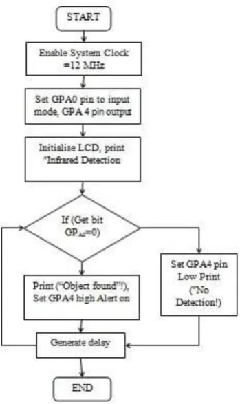
Flow chart design 1As shown below fig 5 infrared sensor is interfaced with the ARM processor first we have to set the clock frequency 12 MHz in this case GPAO general purpose input output pin is set to 1 and GPAO 4 pin is set as output mode.at pin no GPAO when it became 0 it indicate some object is detected in front of sensor module after then processor check condition GPAO pin low if yes give the alert on make indicator LED On as well as display the output as object detected if pin become high there is no change in the state of the output processor .and infrared sensor keep observing object within the specified range
Fig.5 Flow chart design infrared
Hardware testing
Ultrasonic sensor testingAs shown below prototype design module was tested. Ultrasonic module is detecting object, also it is calculating distance one condition is put on programming, that if distance is below 15 cm give the alert. It will make led on this is successfully tested on ARM board and tested successfully with different conditions.
Fig. 6 Ultrasonic sensor module testing.
Infrared sensor testing
Fig.7 Infrared sensor.
Result analysis
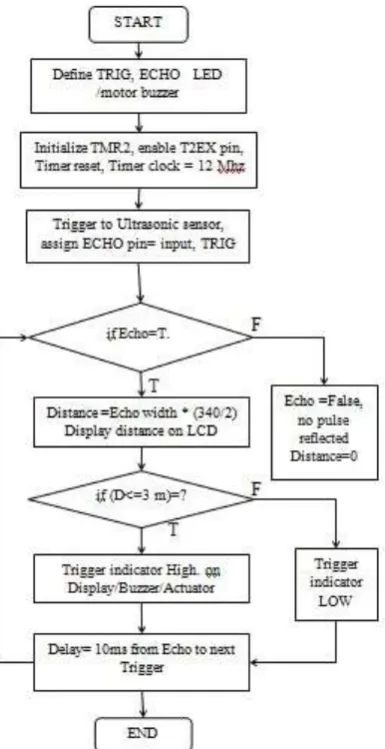
Ultrasonic sensor Mathematical calculation1. Test distance = (high level time× (velocity of sound 340M/S)/ 2) 2. Trig input: 10 us clock pulse
3. Distance =Echo width * (340m/s)/2) 4. Echo width = (distance*2)/340 m/s 5. Echo width capture mode on by Timer 6. Observed distance maximum range : 7- 8 m
7. 3.5m >= 8 m < No indicator on but measures accurate distance 8. If distance < 3 m alert on to driver
Infrared sensor
Following results are observed as prototype model while detection of infrared sensor 1. Manufacture range 2 m
2. Observed range maximum up to 1.5 m 3. Obstacle detection in between 10 cm to 1.5m 4. No distance measurement
5. Very poor communication range
Conclusions
With the ultrasonic and infrared sensor modified blind spot/collision avoidance system was designed and the above prototype model was tested on ARM Nuvoton boards. Sensor working range efficiency was tested successfully Software testing was done on Keil u vision 4 ARM. And hardware testing also was done successfully. In this way blind spot detection warning system can be implemented with low cost design system, this method gives better embedded systems design solutions for automobile.
References
1. Thomas Schleg, Thomas Bretterklieber, Markus Neumayer, and Hubert Zangl “Combined Capacitive and Ultrasonic Distance Measurement for Automotive Applications.”
2. Shigang Li and Ying Hai Easy Calibration of a Blinds “Free System Using a Scene of a Parking Spac.”
3. Bao Rong Chang, Hsiu Fen Tsai Chung-Ping Young “Intelligent data fusion system for predicting vehicle collision warning using vision/GPS sensing.”
4. J. Wiciak, B. Borkowski and D. Czopek “System for Identification of Dangerous Spots and POIs for the Blind and Visually Impaired.”
5. Jiann-Der Lee and Kuo-Fang Huang A “Warning System for Obstacle Detection at Vehicle Lateral Blind Spot Area.” 6. Raymond J. Kiefer Jonathan M. Hankey “Lane change behavior with a side blind zone alert system.”
7. Steven De Lausnay, Thomas Standaert and Nobby Stevens Wout Joseph, “Zigbee as a Means to Reduce the Number of Blind Spot Incidents of a Truck.”