427 | P a g e
DVR BASED VOLTAGE SAG COMPENSATION USING
NOVEL PARTICLE SWARM OPTIMIZATION
TECHNIQUE
Dr.S.Siva Prasad
1, A.Praveen Kumar
2,
S. Suresh
31
Professor, Dept. of EEE ,Vidya Jyothi Institute of Technology, Hyderabad.
2,3
Asst. Professor, Dept. of EEE ,Vidya Jyothi Institute of Technology.
ABSTRACT
Execution of particle swarm optimization (PSO) application for solving the optimization problem in the field of
electric power system is proposed. PSO is a dominant tool for optimizing multidimensional discontinuous
nonlinearity problems. The optimization problem in power system like minimization of energy capacity of a
dynamic voltage restorer is identified and analyzed in the proposed work. The increasing interest in power
quality has led to a variety of devices designed for mitigating power disturbances, primarily voltage sags.
Among several devices, a dynamic voltage restorer (DVR) is a novel custom power device proposed to
compensate for voltage disturbances in a distribution system. The compensation capability of a DVR depends
mainly on the highest voltage injection ability and the amount of accumulate energy presented within the
restorer. A novel PSO based algorithm is presented in this paper to tune the integral gain of PI controller which
creates it an automatic tunable controller to some level. The PI controller is been used in the controlling circuit
of Voltage Source Converter of DVR. Simulations carried out in MATLAB/Simulink environment.
Keywords: DVR, PSO, PI Controller, Sag and Swell.
I INTRODUCTION
Modern power systems are complex networks consisting of more number of generating stations and load centers
which are interconnected through the power transmission lines. There are many issues involved here such as
maintenance of the power apparatus in the system and maintaining the stability of the system operation during
fault condition.
The power system especially the distribution system, have numerous non linear loads which significantly affect
the quality of power supply. The deviation of voltage, current or frequency which can be described as a power
quality problems results in collapse or incorrect operation of customer equipment.
Voltage sag/swell, flicker, harmonics distortion, impulse transients and interruptions are the various power
quality problems addressed in the distribution system. Of the above power quality problems, a voltage sag/swell
disturbance poses a series threat to the industries. It can occur more frequently than any other power quality
phenomenon.
Voltage sag is defined by the IEEE 1159 as the decrease in the RMS voltage level to 10%-90% of nominal, at
the power frequency for duration of half to one minute. Voltage swell is defined by IEEE 1159 as the increase
428 | P a g e
minute .
Dynamic voltage restorer (DVR) is one of the power electronic devices connected in series to the distribution
system. It compensates the voltage disturbances by injecting the voltage of suitable magnitude and phase in
series with the line. The DVR, with its excellent capabilities, when installed between the supply and the
sensitive load, can compensate voltage sag/swell .
A Z-source inverter based DVR has been implemented. It employs a unique X-shaped impedance network on
its DC side for achieving both voltage buck and boost capabilities This uniquefeatures of ZSI cannot be
obtained in the traditional voltage source and current source inverters.
Here the control scheme used employed in Z-source inverter based DVR is fuzzy controller. The most common
choice controller of the DVR is the PI controller since it has simple structure and it can offer relatively
satisfactory performance over a wide range of operation. But by using fixed gains, the controller may not
provide the required control performance, when there are variations in the system parameters and operating
conditions. It appears that the non linear controllers are more suitable than the linear type since the DVR is truly
a non linear system. The fuzzy controller will provide the desired injecting voltage.
PSO has been applied in many fields, such as distribution state estimation, dynamic security border
identification, optimum design of PID controller [9] and so on, since it was proposed in 1995 [10]. PSO
self-tuning PI controller does not need offline training like ANN controller, so it is not that time-consuming. On the
other way, the PSO self-tuning PI controller does not require inference rules which are essential for fuzzy
control. Thus, PSO provides more effectiveness. However, PSO is rarely used in the control of DVR.
This paper presents a PSO algorithm to realize a self-tuning integral controller of PI controller of the DVR. The
control aim is to maintain a constant voltage profile under different loads. The control system of DVR should
respond quickly and achieve the required controller gains in a short time by using PSO.
The contents of this paper are as follows. For the DVR control system, the model of the system is deduced.
Then, a PSO self-tuning controller is designed for a DVR. Finally, the simulations are studied to verify the
effectiveness of the PSO-based self-tuning Integral controller of PI controller.
II DYNAMIC VOLTAGE RESTORER
A power electronic converter based series compensator that can protect the critical loads from all the supply side
disturbances other than outages is called dynamic voltage restorer. This device employs solid state power electronic switches in the inverter structure. It injects a set of three phase AC output voltage in series and synchronism with the distribution feeder voltages. The DC input terminal of the restorer is connected to an energy storage device of appropriate capacity.
429 | P a g e
Figure1. DVR general configuration INJECTION TRANSFORMER:
The injection transformer is connected in series with the sensitive load which is to be protected by the DVR.
The basic function of this transformer is to connect the DVR to the distribution system and the injected voltages
generated by the inverter are introduced into the distribution system.
FILTER
The main task of the filter is to keep the harmonic voltage content generated by the inverter within the
permissible ( ie it eliminates high frequency switching harmonics) level.
Z-SOURCE INVERTER
Z-Source inverters are the buck- boost inverters that contain unique passive input circuits (impedance
networks) and utilize the shoot-through of the inverter bridge to boost the DC input voltage.
ENERGY STORAGE DEVICE
It provides the real power requirement of the DVR during compensation. It is responsible for the energy storage
in DC form. Flywheels, lead acid batteries,superconducting magnetic energy storage (SMES) and super
capacitors can be used as energy storage devices. Here in the form of DC supply from the energy storage system
is given to the inverter.
BASIC OPERATION OF DVR
The basic operating principle of DVR is to inject proper series voltage to the grid in order to restore the load
voltage level to its desired level.
Figure2: Equivalent circuit
As shown in figure2 the Z- impedances Zth depends on the fault level of load bus. When the system voltage Vth
drops, DVR injects the series voltage VDVR through the injection transformer so that the desired voltage
magnitude VL can be maintained. The series injected voltage of DVR can be written as
VDVR = VL + Zth IL – Vth
430 | P a g e
IL : Desired load current
Vth : System voltage during fault condition.
III Z-SOURCE INVERTER
The inverter topology used in conventional DVR is both VSI and CSI. The VSI topology based DVR has buck
type output voltage characteristics thereby limiting the maximum voltage that can be attained. Therefore the use
of VSI topology alone in DVR systems with dwindling dc-link voltage in the energy storage device would pose
a problem. The main disadvantage of CSI topology is it‟s basically a boost converter. For applications where a
wide voltage range is required, extra circuitry has to be used to obtain the required voltage. However, this
increases the circuit complexity and reduces the efficiency as well as the reliability.The Z-source inverter has
been an alternative to the existing inverter topologies with many inherent advantages. The Z-source inverter has
an additional zero vector, the shoot-through switching state, which is forbidden in the traditional voltage and
current source inverter. Compared to VSI and CSI, Z-source inverter is less affected by the EMI noise In this
paper, voltage type Z-source inverter based topology is implemented where the storage device can be utilized
during the process of load compensation along with the use of buck boost property of the inverter. A series
diode is connected between the source and impedance network, which is required to protect the source from a
possible current flow.The impedance network is the combination of two inductors and capacitors. This
combination network circuit is the energy storage are filtering element for the impedance source inverter. The
impedance source inverter provides the second order filter. This is more effective to suppress voltage and
current ripples. The inductor and capacitor requirement should be smaller compared to the traditional
inverter.When the inductors are small and approach zero, the impedance source network reduces to two
capacitors in parallel and becomes traditional voltage source. Considering additional filtering and energy storage
provided by the inductors, the impedance source network should require less capacitance smaller size compare
with the traditional voltage source inverter. Similarly when two capacitors are small and approach zero, the
impedance network reduces to two inductors in series and becomes traditional current source. Therefore a
current source inverter‟s inductor requirements and physical size is the worst case.
IV FUZZY LOGIC CONTROLLER
The fuzzy logic controller unlike conventional controllers does not require a mathematical model of the system
process being controlled. However, an understanding of the system process and the control requirements is
necessary. The fuzzy controller designs must define what information data flows into the system (control input
variable), how the information data is processed (control strategy and decision) and what information data flows
out of the system (solution output variables).
In this study, a fuzzy logic based feedback controller is employed for controlling the voltage injection of the
proposed dynamic voltage restorer (DVR). Fuzzy logic controller is preferred over the conventional PI and PID
controller because of its robustness to system parameter variations during operation and its simplicity of
implementation. The proposed FLC scheme exploits the simplicity of the mamdani type fuzzy systems that are
431 | P a g e
Figure4: Fuzzy logic controller
V PSO- PI CONTROLLER DESIGN
5.1. Introduction
In PSO algorithm, the system is initialized with a population of random solutions, which are called particles,
and each potential solution is also assigned a randomized velocity. PSO relies on the exchange of information
between particles of the population called swarm. Each particle adjusts its trajectory towards its best solution
(fitness) that is achieved so far. This value is called pbest. Each particle also modifies its trajectory towards the
best previous position attained by any member of its neighborhood. This value is called gbest. Each particle
moves in the search space with an adaptive velocity.
The fitness function evaluates the performance of particles to determine whether the best fitting solution is
achieved. During the run, the fitness of the best individual improves over time and typically tends to stagnate
towards the end of the run. Ideally, the stagnation of the process coincides with the successful discovery of the
global optimum.
5.2. PSO Algorithm
1) Initialize the swarm by randomly assigning each particle to an arbitrarily initial velocity and a position in
each dimension of the solution space.
2)Evaluate the desired fitness function to be optimized for each particles position.
3) For each individual particle, update its historically best position so far, Pi if its current position is better than
its historically best one.
4) Identify/Update the swarm‟s globally best particle that has the swarm„s best fitness value, and set/reset its
index as g and its position at Pg .
5) Update the velocities of all the particles using equation.
(1)
6) Move each particle to its new position using equation.
(2)
7) Repeat steps 2-6 until convergence or a stopping criterion is met (e.g., the maximum number of allowed
iterations is reached, a sufficiently good fitness value is achieved or the algorithm has not improved its
432 | P a g e
VI MATLAB/SIMULATION RESULTS
Figure5: Simulation Circuit of System with DVR
Figure6: Control Circuit of DVR
433 | P a g e
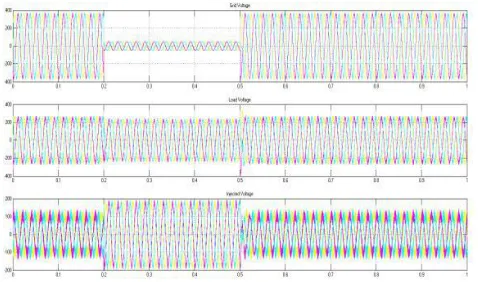
Figure 8: a) Source Voltage b) Load Voltage c) Injected Voltage with DVR
VII CONCLUSION
In this paper it has been seen that automatic tuning of integral gain value for PI controller. We have been done
the simulation on PI plus FUZZY based DVR for the power quality improvement in the distribution system
notably the compensation of voltage sag and swell. We have written a particle swarm optimization based
algorithm for tuning the integral gain of PI controller which provided us the automatic controller.
REFERENCES
[1] Lim, P.K, Dorr, D.S., “Understanding and resolving voltage sag related problems for sensitive industrial
customers”, Power Engineering Society Winter Meeting, 2000. IEEE, Volume 4, Jan 2000, Page(s):2886-2890.
[2] Hingeroni, N.G, “Introducing custom power”, IEEE Spectrum, 1995, 1, pp. 41-48.
[3] N. H. Woodley, L. Morgan, and A. Sundaram, “ Experience with an inverter-based dynamic voltage restorer” , IEEE Trans. Power delivery, vol. 14, pp. 1181-1186, July 1999.
[4] Math H. J. Bollen, “Understanding Power Quality Problems” . A volume in the IEEE Press Series On
Power Engineering, 2000.
[5] Chellali Benachaiba, Brahim Ferdi “ voltage quality improvement using DVR” Electrical power quality
and utilization, journal vol. XIV, No. 1, 2008.
[6] F. A. L. Jowder, “ Design and analysis of dynamic voltage restorer for deep voltage sag and harmonic
compensation” , IET Gener. Transm Distib., 2009, vol. 3, Iss. 6, pp. 547-560.
[7] oodley N. H., Morgan. L., Sundaram A., “ Experience with an inverter based dynamic voltage restorer‟ ,
IEEE Trans. Power Deliv., 1999, 14, (3), pp. 549-557.
[8] C. E. Thenmozhi, C. Gopinath, R. Ramesh, “ A Novel Method For Voltage Sag/Swell Compensation
Using Dynamic Voltage Restorer”,IEEE Trans., 978-81-909042-2-3,March 2012.
[9] Joseph J. DiStefano, Allen R. Stubberud, Ivan Williams,Feedback and control systems, McGraw Hill
434 | P a g e
AUTHORS PROFILE
Dr. S.Siva Prasad, Professor, EEE has awarded Ph.D Electrical Engineering in
2012(February) from J. N. T. UNIVERSITY HYDERABAD and had his M.Tech with
specialization of Power Electronics in 2003.He has obtained his B.Tech Degree in Electrical
and Electronics Engineering from S V University. He is having 19 years of Experience and
currently working as Professor Vidya Jyothi Institute of Technology, AzizNagar , Hyderabad ,
India . He received “Bharat Vibhushan Samman Puraskar” from “The Economic and Human Resource Development Association” in 2013 and received Young Investigator Award in 2012. He has published about 60
technical papers in International and National Journals and Conferences and filed one patent. He is Life
member of ISTE and member of IEEE. His Research areas include Power Electronics & Drives, PSD&FACTS
Controllers.
Praveen Kumar was born in India in 1993. He received his bachelor‟s degree from JBIT
from Jawaharlal Nehru Technology University Hyderabad-Telanagna, in 2013 and Master of
Technology in Electrical Power Systems (EPS) from Vidya Jyothi Institute of Technology,
AzizNagarGate, C.B. Post, and Hyderabad-75 from the same university. Currently working
as Asst. Professor Vidya Jyothi Institute of Technology, AzizNagar , Hyderabad , India .
Shamanty Suresh was born in India in 1991. He received his bachelor‟s degree from
KGRCET from Jawaharlal Nehru Technology University Hyderabad, kukatpally
Hyderabad-Telanagna in 2013. He is currently pursuing Master of Technology
in Electrical Power Systems (EPS) from Vidya Jyothi Institute of Technology,
AzizNagar Gate, C.B. Post, and Hyderabad-75 from the same university. The areas of