http://www.sciencepublishinggroup.com/j/ajtte doi: 10.11648/j.ajtte.20170204.12
Drunk-Driver Detection and Alert System (DDDAS) for
Smart Vehicles
Rajesh Kumar Jakkar, Roop Pahuja
*, Raj Kumar Saini, Bhagirath Sahu, Natwar
Department of Instrumentation and Control Engineering, Dr B R Ambedkar National Institute of Technology - Jalandhar, Jalandhar, Punjab, India
Email address:
[email protected] (R. Pahuja) *
Corresponding author
To cite this article:
Rajesh Kumar Jakkar, Roop Pahuja, Raj Kumar Saini, Bhagirath Sahu, Natwar. Drunk-Driver Detection and Alert System (DDDAS) for Smart Vehicles. American Journal of Traffic and Transportation Engineering. Vol. 2, No. 4, 2017, pp. 45-58.
doi: 10.11648/j.ajtte.20170204.12
Received: July 25, 2017; Accepted: August 10, 2017; Published: September 1, 2017
Abstract:
One of the major causes of road accidents, crashes, mishaps and fatalities globally all over the world is drunk driving. Though driving under intoxication is illegal, even then people restore to such hard-core habits often. In order to combat such risky situation on road, technological innovation needs to be implemented in a cost-effective, efficient and legal manner. This paper discusses design, development and live-performance test of the prototype of drink and drive situation detection and alert cum vehicle control system to minimize road mishaps and enhance public safety on road. It also analyses the response of breath –alcohol semiconductor sensor with respect to variation in distance from source which is critical part of system design. Based upon the recent smart gas sensing and integration of satellite and cellular wireless communication technologies, the proposed device quickly senses the drunken state of the driver during start-up/driving by estimating the equivalent breath alcohol concentration level corresponding to the legally permissible state’s threshold blood alcohol concentration level. On detection of such situation, on-vehicle siren/audio alarm is activated to warn the persons on road and vehicle control system is triggered to lock ignition or stop the fuel inflow to the vehicle. Additionally, ‘alert SMS’ indicating drunk driver location, tracked by onboard GPS receiver, along with vehicle number is communicated remotely to authorized (family members, traffic police) mobile user using GSM cellular network to take appropriate action thereafter. The live experiment results highlighted the successful working performance of the device in-housed at the steering wheel of the vehicle with the drunk driver.Keywords:
Embedded System, Drunk-Driver detection, Location Tracking, Semiconductor Alcohol Gas Sensor, Short Message Communication1. Introduction
Long back the revolutionary invention of wheel has given man the idea to innovate means of transportation to move/carry goods from one place to another. Over the decades, advances in science and technology in automotive industry have produced generation of vehicles, with the present day smart vehicles that are now being part of the Intelligent Transportation Systems (ITS), gradually gaining pace [1-3].
Intelligent transportation system applies information
processing, communication, and sensor technologies to vehicles, transport users and infrastructure to increase the effectiveness, environmental performance, safety, comfort,
resilience and efficiency of the transportation system [4]. With the advances in dedicated short range wireless communication [5], the enabling technology of Vehicular Area Networks (VANETs), a special class of Mobile Ad-hoc Networks (MANETs) have become a cornerstone of the envisioned Intelligent Transportation Systems. This enables vehicles to communicate with each other and/or roadside base stations to provide timely information to drivers and concerned authorities about safe and efficient driving on road [6].
level of the occupants/ persons on road [7-8]. In today’s modern and/or automatic vehicles/cars many safety systems such as air bags, automatic brake control, lane departure, obstacle detection, and collision/accidents avoidance [9-11], vehicle tracking device [12-14], automatic collision and theft notification [15-16] or fuel quality indicator [17] etc. are embedded into the vehicle/voluntarily installed [18] or such technological innovations are under the development phase.
Though the vehicles are becoming more intelligent, but the persons driving the vehicles are becoming careless, ignorant and irresponsible on certain issues. Cases such as rash and reckless driving and/or driving under drunk/intoxicated state that lead to road accidents, serious injuries to persons involved, mishaps and loss of lives apart from physical damage to vehicles are continuously being reported every year. According to National Crime Records Bureau [19] complied data, in India one serious road accident in the country occurs every minute and 16 die on Indian roads every hour. Fig. 1 shows that more than 14% of accidents in non-dry state of India are due to drunk drivers as against 1.4% accidents in the dry states of the country [19]. But the fatality rate in such accidents is quiet high, 42-70% as against other causes of accidents. In India, due to the government initiatives to ban liquor sales near highways and in many cities have reduced the percentage of road accidents due to drunk driving, even then the situation is complex [20]. It is rather a serious problem than statistics indicate [21-22]. In one of the latest report compiled by National Highway Traffic Safety Administration, Washington, DC [23], Fig. 2 shows the number of fatalities and fatality rate per 100 million vehicle miles travelled (VMT)
in alcohol-impaired driving crashes in USA from 2005-2014. Though the trend has decreased over the years but it is still high. There was 31% of total traffic fatalities in 2014, an average of one alcohol-impaired driving fatality in every 53 minutes, due to drunk driving involving driver with BAC (blood alcohol concentration) of 0.08 g/dL or higher. The figures in the reports are shocking and have attracted attention of the societies and state government of the countries to make strict traffic and driving rules and also spread awareness among people not to drink and drive. Apart from this, advances in science and technology have great role to play to innovate systems to combat such adverse situation on road.
Technically, the driver whose blood alcohol concentration (BAC) level exceeds the state’s maximum permissible BAC level (typical 0.8g/L or 80mg/100ml in USA and 0.4g/L or 40mg/100ml in India) is generally called as drunk driver [24]. Driving under intoxicated (DUI) state or drinking while intoxication (DWI) (referred to as drunk driving), after/during consumption of alcoholic beverages impairs driver’s ability to think, see, judge distances and take appropriate timely actions for safe driving, hence increasing high risk of accidents and loss of lives [24-25]. One of the metrics to identify drunk driver is the measure of blood alcohol concentration (BAC) which is the ratio of concentration of alcohol (in unit of mass) per unit of volume of blood of the person [26]. Since BAC is a laboratory test and on-road instantaneous detection of BAC of drunk driver is not possible, an alternative and equivalent value of breath alcohol concentration (BrAC) is measured by specific devices called breath analyzer [27] and correlated to BAC value [26].
Figure 2. Fatalities and fatality rate per 100 million vehicle miles travelled (VMT) in alcohol-impaired driving crashes in 2005-2014 in USA [23].
Drunk driving is one of the very serious national and global road safety problem. Though driving under the drunken condition is illegal and punishable in almost every country, even then many persons/ young children, break the rules and feel excited to drink and drive. Presently, to prohibit drunk driving on road and minimize road mishaps is a major road safety challenge, where the recent technological developments have great role to play. Motivated by the idea, this project work has been undertaken. The basic idea revolves around the concept --- Why not make the vehicle smart enough to check the drunk state of the driver and take alerting and preventive actions before any mishap on road?
This paper discusses the design, development and in-vehicle testing of the proposed drunk driver detection and altering system (DDDAS). The work is done with the aim to increase the safety mechanism of smart vehicles by embedding a reliable drink and drive situation detection device in the steering wheel of the vehicle that automatically detects the alcohol content in the exhaled breath of the drive and indicates the alarming drunk state of the driver. On detecting the drunk driver state, the alert unit activates the siren on the vehicle that generates peculiar loud noisy sound to warn the passengers/vehicles on the road. Apart from this, vehicle location is tracked by satellite global positioning system (GPS) and ‘alert SMS’ (short message service) with the vehicle number and location is also communicated remotely using GSM (global system for mobile communication) modem to the mobile phone numbers of authorized persons (traffic police, family members) to take appropriate actions thereafter. Additionally, a triggering unit is designed to activate the vehicle control units such as ignition interlock or engine fuel cutoff as preventive mechanism. This will enable to stop the vehicle from initial start-up or gradually halt the vehicle in a safe mode during run time when drunk driver situation is detected.
As compared to the commercially used breath analyzer [27] or ignition antilock device [28] or other related works described in literature, the proposed system is a low cost, automatic device that can be integrated in a vehicle to detect
the drunk state of the driver on the wheel. Using the device, drunk state of the driver is detected prior to driving or continuously during the driving condition. Secondly, the proposed device is different from others as it is not using the sensitive thin-film alcohol gas sensor but estimates more accurate 20-point average value of alcohol sensor at a fast rate (within 1s of time interval). Performance of the sensor with variation of sensing distance from alcohol source is also tested to estimate time-lag. Moreover, the system is standardized and configured to cope with the state’s permissible BAC or equivalent BrAC level to detect drunk driver. Also, the use of siren to provide noise tones under drunk driver situation detection enhances the local alert mechanism along with remote SMS ‘alert’ with vehicle number and location using GPS and GSM communication. Further, the live-test and successful demonstration of the working of proposed system prototype is done by installing the system in a vehicle with drunk driver.
2.
Related Works
vehicle exhaust and pollution level and unnecessary harassment to others who abstain from drinking. Another commercially used device is ignition interlock [27-28] that allows the driver to start the vehicle if the alcohol detection test is passed otherwise prohibits the driver to drive the vehicle. The device is generally fitted in the vehicle and requires the drive to undergo breath alcohol test and activate the ignition system if test is passed. This device monitors the alcoholic state of the driver and takes preventive action during start up but does not guarantee alcohol detection during vehicle run condition. In one of the recent joint research project on driver alcohol detection system for safety (DADSS), the auto companies are investigating technological solutions based upon breath-type and touch–breath-type alcohol sensing methods that can be reliable, cost-effective and can be integrated seamlessly in vehicles to stop the vehicle from moving once BAC of driver exceeds the limit of 0.08 g/dL, the legal limit in 50 states of USA [32].
A few of the works indicated different sensing methodologies for drunk driver detection such as the use of chemical gas sensor [33], design of more accurate alcohol sensor with electric fan suction and oxygen level detection of exhaled breath [34], use of body area sensors for alcoholic and mood dysfunctional detection [35] and detecting behavior pattern of driver using iris image capture and processing to detect eyes condition that is affected by blood alcohol concentration level [36]. Many proposed the embedded hardware of the system without discussing the results such as an alcohol sensor with GSM module to send message, use of global position system to track drunk driver location or use of additional ultrasonic sensor to detect accident and track location [37-38]. Others, proposed additionally different ideas of vehicle control to prohibit driving under the detection of drunk driver condition such as triggering of ignition interlock system [33], [39]. Also, the idea to use latest technology of vehicular area networks by incorporating the sensors in vehicles to communicate with other vehicles and/or with roadside sparse network devices was proposed for detecting drunk drivers on road. This would enable timely sharing of collectively information of drunk drivers, accidents or road congestion problem etc. among the vehicles on the road thus enhancing on-road safety of many vehicles [7].
3. System Design and Hardware
The proposed drunk-driver detection and alert system (DDDAS) is implemented by leveraging the smart gas sensing, embedded computation, mobile communication and satellite based location tracking technologies and integrating the same with vehicle control system for autonomous operation. The design of the system is backed by breath-based alcohol gas sensing method that monitors breath alcohol concentration (BrAC) of the driver from fixed distance in an obstruction-free manner. The sensor signal activates the alert system and/or vehicle control unit when
BrAC equivalent to BAC level crosses the preset legal limit as standardized by the countries.
A few of the important design challenges are: (i) to design a system that can reliably sense the driver breath alcohol concentration at a certain distance from the driver in contrary to the mouth-piece breath analyzer and is convenient to house in the vehicle without causing obstruction to the driver (ii) the system should be able to differentiate among the drunk drivers and others in the vehicle, initiate alert signal timely to warn local traffic on road (iii) the system must support remote communicate of alert SMS with vehicle tracking information to authorized persons and take timely preventive mechanism to stop driving under such condition.
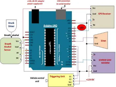
Fig. 3 and Fig. 4 show the block diagram and circuit schematic of the proposed system respectively. The system consists of low power, small size modular components that are interfaced to an embedded microcontroller ATmega328 on Arduino Uno. It an integrated system that is housed on the steering wheel of the vehicle to detect drink and drive situation, activate an ‘audio alert’, send remote ‘alert message’ to authorized person and stop the vehicle from start up. The specific hardware components used in the system are explained below:
variable load resistor [40]. The change in the voltage is measured by the microcontroller as equivalent digital count. The sensor has lower conductivity in clean air, but offers
high sensitivity to target alcohol concentration as it increases in the vicinity of drunk driver [44].
Figure 3. Block diagram of the proposed drunk-driver detection and alert system (DDDAS).
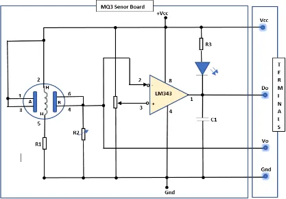
Construction and Interfacing: As shown in Fig. 5,
smart alcohol gas sensor MQ3 is thin-film based
semiconductor gas sensor. The sensor consists of thin sensitive layer of tin-dioxide (SnO2), measuring electrodes and heater that are fixed into a crust made of plastic and stainless steel net with has six terminals (H-H, A-A, B-B) to provide excitation and obtain output [41, 45]. The sensor is fixed on to a board with appropriate signal conditioning (Fig. 6)to convert sensor output to standard voltage range [41]. One of the heater terminals (H) and one of the electrodes (A or B) are given DC excitation of 5V. Other electrode (A or B) acts as output terminal and is connected in series with a variable resistor (potentiometer), typical value of 200 kΩ, to measure output voltage of the sensor with respect to the ground terminal, connected to other heater terminal H. Fixing the internal connections of the circuit, the sensor board provides 4-terminals (Vcc, Gnd, A0, D0) for interfacing to microcontroller [40]. As shown in the system circuit diagram (Fig. 4), MQ-3 sensor is powered by the microcontroller 5V DC excitation and output voltage across the resistor is interfaced to the analog input channel (A0) of the microcontroller which has built-in 10-bit ADC. Increase in breath alcohol concentration increases ADC count of the analog channel A0 that is read on the serial monitor.
Threshold and sensitivity adjustment: Prior to the use of the sensor, sensitivity adjustment is done to make the sensor more sensitive to alcohol concentration as compared to other constituents. Load resistance value of MQ-3 is different for detection of different constituents of gases in air and controls device sensitivity and selectivity to particular constituents [44]. For detection of breath alcohol concentration, it is recommended to calibrate the detector for the specific alarm point [40]. For alcohol detection, the alarm point for MQ-3 sensor corresponds to the value of BrAC equivalent to legal standard threshold value of BAC fixed for the state under DUI (driving under intoxicated state) laws [24]. Driving with blood alcohol concentration of more than 0.8g/L is considered illegal in many countries of the world.
To be more precise, the breath alcohol concentration is different from blood alcohol concentration. When a person drinks, only the air in the deepest portion of the lungs, the alveolar sacs is in equilibrium with blood alcohol. The amount of ethanol in the lung of individual under breathing test is very small as compared to BAC. A typical value of blood to breath alcohol ratio (BBA) is given as 2100:1 [26]. The equivalent BrAC threshold limits corresponding to BAC threshold value depends upon BBA and is given by equation (1).
BrACthreshold = BACthreshold / 2100 (1)
= (0.8 g/L) / 2100
= 0.4 mg/L (2)
For critical value of breath alcohol concentration of 0.4 mg/L and using recommended load resistor value of 200 kΩ (within range 100 kΩ to 470 kΩ), ADC count of microcontroller corresponding to the output voltage of the sensor is 500 [40]. Initially sensor is calibrated in air. When the sensor is placed in the clean air, assuming very low concentration of alcohol i.e. 0.05mg/L the ADC count varies from 60-70, being the offset. Based upon the input-output values under the initial and critical alcohol concentration, approximate sensitivity of the sensor is calculated and is given by equation (3).
Salcoholsensor = (500 - 65) / (0.4 - 0.05) (3)
= 1242 ADC count per mg/L of alcohol concentration (4)
The maximum value of alcohol concentration (high range) measurable by the sensor corresponding to full scale ADC (10-bit) output of 1023 is given by equation (5).
Max_Alcoholcon = 1023/Salcoholsensor
= 0.8186 mg/L (5)
Detectable range of alcohol sensor varies in the range 0.05 – 0.8 mg/L that is sufficient to detect the drunk driver with BrAC of 0.4mg/L (or higher) equivalent to BAC of 0.8g/L (80mg/100mL), the state permissible threshold BAC value for drunk drivers. The sensor has high sensitivity to alcohol and good resistance to disturbing components in air such as of gasoline, smoke and vapor. It has wide detecting scope, fast response, stable output, long life and simple drive circuit that make the sensor well suited for embedded alcohol detection applications [40-41].
(b)System controller:The heart of the proposed system is an embedded microcontroller, ATmega 328 on Arduino Uno board [46]. It is interfaced to all system components (Fig. 4) and runs the control program for its operation. The embedded control program is downloaded in the flash memory of the microcontroller that controls the working of the system.
of SRAM and 1 KB of EEPROM. The board supports communication serially with PC over USB for display of results on serial monitor and for loading programs in the flash. For easy of interfacing it supports plug-in type of wire connectors and status LEDs for visualizing microcontroller operation [46-47].
The AVR microcontroller is typically programmed using a dialect of features from the programming
languages C and C++. In addition to using traditional compiler tool chains, the Arduino project provides an integrated development environment (IDE) based on the Processing language project [48]. A program for Arduino may be written in any programming language for a compiler that produces binary machine code for the target processor.
Figure 5. Semiconductor alcohol gas sensor (a) MQ3 device look-out (b) Cross-sectional view of thin –film MQ3 sensor design.
(c)Location tracking device: For tracking the location of the drunk driver for remote communication, satellite based GPS (global positioning system) receiver module, with antenna is used. GPS module used in the system uses civilian GPS signal to provide location accuracy of 30-50 m within 5 minutes or less, the initial time required to lock the satellite in a moving vehicle [49]. The purpose of the active tracker is to get the real-time location information of vehicle with drunk driver and transmit the same to the client mobile using GSM modem attached to controller. Global positioning system, owned by USA, is a worldwide radio-navigation system formed from the constellation of 24-32 Medium Earth Orbit satellites (NAVSTAR) and their ground stations. Satellites broadcast precise microwave signals to the ground GPS receiver units repeatedly at a time gap of 30 seconds modulated with navigational information about its current location and time stamp etc. Each GPS receiver continuously tracks the strongest satellite signals from at least 3-4 satellites at a time and calculates its distance from each satellite location. Distance is calculated using velocity of electromagnetic radiation and transit time of the signal from transmitter to receiver. Further, the distance data is triangulated from at least three satellites to calculate the absolute geographical location (latitudes, longitude and elevation) of the receiver unit. The location data from GPS is available serially to the microcontroller using USB interface [50-51].
GPS Interfacing: GPS receiver module is a 4-terminal (Vcc, Gnd, Tx, Rx) device and is interfaced to microcontroller as shown in Fig. 4. The module receives power at its VCC terminal from 5V terminal of microcontroller with ground terminals of both devices connected together. For data communication, GPS transmitter (TX) pin is connected to microcontroller digital input pin (D12) and software serial library in included in the control program to interface microcontroller TTL digital pins for serial communication with the device. GPS module communicates its navigational string data in four different
sentences in NMEA (National Marine Electronic
Association) format serially to microcontroller that is decoded by the system software to get the location information of the vehicle [52].
(d)GSM Modem:GSM modem (modulator-demodulator),
SIM 900MHz, is an important component of the system that facilitates remote communication of ‘SMS alerts’ with location and vehicle number of drunk driver to the mobile phones of authorized persons (police station and/or family members). Based upon the traditional digital cellular network standard, known as Global System for Mobile Communication (GSM)/2G network, the modem supports short message services (SMS) or ‘text’ messaging to mobile phones. It uses the usual SIM (subscriber identification module.) card inserted into its slot provided by the cellular network
service provider to communicate over the network and
‘AT commands’ for communication with
microcontroller using serial interface [53]. The modem operates at 900MHz frequency band widely used in India and many countries and provides low cost, fast speed (until 120Mbps), long range mobile coverage for embedded applications. GSM digitizes and compresses data. It uses variation of time division multiple access (TDMA) technique to send data down a channel with two other streams of user data, each in its own time slot [54]. To power the device, external DC adapter of 12V, 2A is used. The interface between the host PC or microcontroller with GSM modem is textual, using AT commands as used in the protocols specified in the GSM standard. The AT commands are executed on hyper terminal or serial terminal software such as Arduino IDE for message communication in textual form on particular mobile phone number/s from GSM modem and provides a convenient way to use mobile communication functions in an application [53], [55].
GSM interfacing and booting: GSM module
communicates with microcontroller serially over its transmitter and receiver terminals. In this work GSM is
configured to transmit SMS to remote user, so GMS modem
receiver (Rx) pin is interfaced to UART TTL serial communication transmitter pin (Tx) as D1 to transmit data received serially from microcontroller over cellular network as shown in the Fig. 4. The device is powered at its power terminals (Vcc and Gnd) using external DC adapter of 12V [56]. Once connections are done and SIM is inserted, device is booted to check its working condition. Since the modem shares the microcontroller TTL serial pins with serial monitor so while loading the embedded program to microcontroller through PC, modem is disconnected and is again connected for operation [55]. In this work, GSM modem is used for transmitting SMS message in unidirectional transmission mode. The location information from GPS is framed into a short message and transmitted to the inserted mobile numbers through the GSM modem using AT commands in the embedded program.
(e)Siren/buzzer: In order to alert the local
persons/vehicles about the drunk driver on road, electronic siren device that makes typical loud noisy warning sound is used in the vehicle. The siren consists of a loud speaker and electronic amplifier that is powered by system controller. Loudspeaker is installed at the front-end of the vehicle and is interfaced to the system microcontroller at its channels. A siren model used in vehicles follows the standard guidelines and is installed after approval from by competent authorities [57]. The siren to warn drunk driver on the road is different from already used siren system in emergency vehicles such as ambulances, police cars and fire trucks or in vehicles with parking/obstacle sensor.
to the system microcontroller output digital line D8. Digital output controls power to the siren and hence its audio output. The control program, switches the digital line to high state to activate the siren when the drunk driver situation is detected in the vehicle and loud audio tones of specific sound are continuously produced by the vehicle. This warns the persons on the road. Along with audio alert, a visual LED alert is indicated on the system board. The LED is connected to the microcontroller digital line D1.
(f)Vehicle control system: It is any type of automatic safety mechanism that is incorporated in the vehicle to control its operation during start-up to or run time. One such method commonly used is to activate/deactivate the vehicle ignition system. Ignition interlock consists of 5V DC relay that is interfaced to microcontroller to control the vehicle ignition during vehicle start up based upon the drunk state of the driver. When the drunk driver is detected, the ignition interlock relay is activated that locks the ignition of the system and does not allow vehicle to start up. This concept is used during vehicle start-up to check driver drunk state and issue signal to start or stop ignition. Another preventive mechanism that can be used in the vehicle during driving is the fuel cut-off device. Fuel cut-cut-off device has a solenoid control
valve interfaced to the digital output port of the microcontroller and controls the flow of fuel to the engine. When drunk driver condition is detected, the relay is operated to cut-off the supply of the flow so that vehicle comes to a halt steadily without causing accidents.
4. Embedded Control Program
ATmega 328 microcontroller on Arduino Uno is programmed with single application sketch referred to as ‘DDDAS control program’ that is embedded into the flash memory using Arduino IDE software. The program synchronizes and controls the operation of each component. The code is implemented using Arduino IDE programming environment using library functions and header files as driver programs for different components [58].
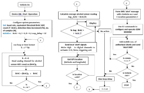
Fig. 7shows the flow chart of DDDAS embedded control
program on Arduino Uno board. Once the set-up is initialized, the program continuously executes functions of drunk condition detection, location tracking, ‘alert’ SMS communication, activation of siren and vehicle control devices continuously in a loop with a delay of one second.
Figure 7. Flow chart of DDDAS embedded control program.
5. Experimental Work and Results
During the design and development work, experiments
5.1. Alcohol Sensor Testing
The test is conducted to check the working of the breath-based alcohol sensor as the distance of sensor from source varies. Since the sensor is used to sense breath alcohol concentration at a certain fixed distance from driver, its performance under different sensing distance is ascertained.
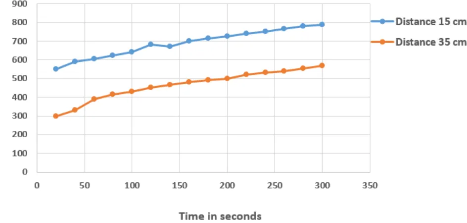
An experiment was set up in a small room to test variation in alcohol sensor output as the distance of sensor from drunk person with certain level of breath alcohol concentration varied. The test was conducted for very less distance of 15cm and distance of 35cm (average distance of car vehicle driver from steering wheel) of alcohol sensor from drunk person and sensor response i.e. changes in ADC count of sensor with time is monitored on the serial panel on PC. Such readings from five tests were saved and average of the readings indicated on graphs as shown in Fig. 8. Comparing the readings on graphs revealed that distance of the sensor from source affected the variation in the output of the sensor.
When the distance was very less (15cm), sensor detected the drunk state of the driver instantly i.e. less than 1s ± 2s as the sensor average output exceeded the threshold value of 500 initially in very less time. When the distance increased to 35cm, as was used in actual test, alcohol sensor average output gradually increased and required around 200s ± 20s to detect the alcohol state of the person. Each reading varied in the range of ±10 counts with respect to its mean value. The variation in time lag also depends upon the level of alcohol content in the blood of the person/driver.
Hence, selection of installation location, distance from source and obstruction free operation of the breath-based alcohol sensor is critical for its successful operation to timely detect the drunk state of the driver in a vehicle. Since very close placement of the alcohol sensor near the mouth of the driver may not be practically possible, hence convenient location of housing the alcohol sensor on steering wheel with average distance of 35cm is an appropriate solution.
Figure 8. Variation in time - response of alcohol sensor to breath alcohol concentration for sensor to source distance of 15cm and 35cm.
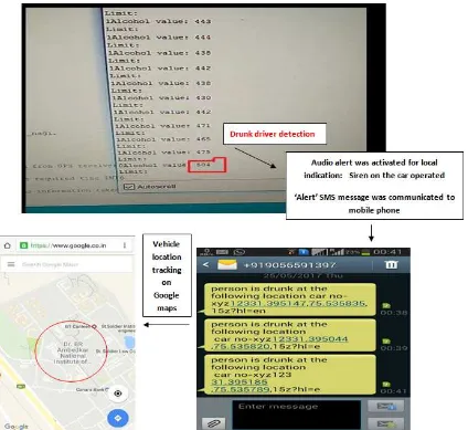
Figure 10. Screenshot of breath-based alcohol sensor output under drunk driving situation detection and communication of ‘Alert SMS’ to remote user to track vehicle location.
5.2. Live Drunk Driver Test
In order to test the real-time working performance of the prototype model of the drunk-drive situation detection system, the system was in-housed on the steering wheel of a car as shown in Fig. 9. A person who voluntarily offered himself for the test, drunk one bottle of alcoholic beverage and was intoxicated. He was asked to drive the vehicle on an empty road. For security reasons, the face of the driver was hide with a cloth to conceal his identity. The video of the real test was made and working performance of the system was evaluated.
When the drunk-driver was driving the car, because of his breathing process, the alcohol concentration in the air near the driver increased gradually and was sensed by the breath–based alcohol sensor fitted in the DDDAS system. As the sensor sensed the alcohol concentration, the sensor output ADC count stated increasing gradually with time. The sensor reading at each instant of time was indicted on the serial virtual monitor. Fig. 10 shows the screenshot of the output readings (ADC_count) of alcohol sensor on serial virtual monitor along with ‘alert SMS’ communicated on client mobile. At each time
instant of one second, value of alcohol sensor was compared with threshold BrAC level ADC count of 500. As the averaged sensor output exceeded the threshold level, the audio alert device, siren on the car operated to indicate the drunk driver situation to the local persons/vehicles on road to avoid accident. Also LED on the panel was activated. The initial detection lag was less than 12 seconds. GPS device of the system that tracked the location of the car, passed the location data indicating latitude and longitude to the microcontroller immediately. The location information along with the car number pre-programmed into the device was framed into the ‘alert SMS’ and was communicated to the client mobile phone using GSM modem with SIM card. On the client PC the location information was passed to the Google maps to track location of drunk driver (Fig. 10).
6. Conclusion and Future Scope
driver situation initially or during the driving condition and activates the alter mechanisms for local persons along with remote indication to the authorized persons. The main aim of the drunk driver detection system in smart vehicle system project is to decrease the chances of loss of lives in accident occurring because of intoxicated state of driver and hence improve public safety.
Based upon the latest semiconductor gas sensing technology, satellite based GPS system and high speed GSM 900 MODEM, the system is cost-effective, reliable, fast, at a distance measuring system that can be easily housed in a vehicle. The development cost of the device would be less than $100. The design of the system is in compliance with the standards defined legally for DUI (driving under intoxication) by the state government traffic and road safety governing bodies. Since the design is flexible, by resetting and locking BAC threshold level the system can be used in many countries. More over live test conducted in the vehicle proved the feasibility and utility of such a system.
In the coming years, such a system is going to be mandatory in vehicles and is going to play a major role in making lives secure during driving. Drunk-driver detection in vehicles makes better fleet management with high potential to save lives. Such a system in a vehicle will help parents to avoid the kids to drink and drive. Apart from this, vehicle location tracking and alter system of this kind can be helpful both in case of personal as well as business purpose, improves safety and security of the person on road.
In this paper the device prototype with preliminary experimental results depicting proof-of-the-concept was presented. To ascertain long-term working performance of the system more live tests with different level of drunken state of the driver can be conducted and analyzed. The system reliability can further be enhanced by the use of multi-sensor fusion using breath-based sensors at different locations in the vehicle, vision system to recognize facial/eyes expressions of the driver and/or use of touch sensor etc. There is possibility to incorporate others features such as different security mechanism in the vehicle such as theft, accident detection, fuel quality detection along with vehicle tracking system. Further, developing the system on the latest VANET technologies will help to share the information with others on the road effectively and efficiently.
References
[1] Y. Wang and Hui Qi, “Research of Intelligent Transportation System Based on the Internet of Things Frame”, Wireless Engineering and Technology, vol.3, 2012, pp. 160-166. [2] L. Ward and M. Siman, “Intelligent Transportation System
using IEEE 802.11p: Application notes, Rohde & Schwarz, vol.6, 2015, pp.1-32.
[3] M. Bommes, A. Fazekas, T. Volkenhoff, M. Oeser, “Video based Intelligent Transportation Systems – state of the art and future development”, Transportation Research Procedia,
vol.14, 2016, pp. 4495 – 4504.
[4] Ministry of transport, “Report on Intelligent transportation system (ITS)”, Ministry of transport, New Zealand Government April 2017. [online]
www.transport.goct.nz/ourwork/technology/intelligenttansport ationsystem
[5] M. Andersson, “Short-range low power wireless devices and Internet of Things (IoT)”, Digi-key Electronics, Jan 2014. [6] G. Karagiannis, O. Altintas, E. Ekici, G. Heijenk, B. Jarupan,
K. Lin, and T. Weil, “Vehicular Networking: A Survey and Tutorial on Requirements, Architectures, Challenges, Standards and Solutions”, IEEE Communication, survey and Tutorials, vol. 13, no. 4, 2011, pp. 584-616.
[7] H. Qin, Z. Li , Y. Wang , X. Lu , W. Zhang and G. Wang, “An Integrated Network of Roadside Sensors and Vehicles for Driving Safety: Concept, Design and Experiments, Proceedings IEEE Conference on Pervasive, Computing and Communications, March 2010, Mannheim, Germany. [8] Janani. N and Saranya. N, “Driver Safety Awareness and
Assistance System for Cognitive Vehicle Control”, Proceedings, International Conference on Advanced Communication Control and Computing Technologies, May 2014, Ramanathapuram, India.
[9] F. Paulbenjamin, N. Astoyao, R and Adjetey, “Design and Development of GSM/GPS based Vehicle Tracking and Alert System for Commercial Inter City Bus, IEEE 4th International Conference on Adaptive Science and Technology, 2012. [10] S. P. Bhumkar, V. V. Deotare, and R. V. Babar, “Accident
Avoidance and Detection on Highways”, International Journal of Engineering Trends and Technology, vol. 3, no. 2, 2011, pp. 247-249.
[11] K. V. Mutya and S. Rudra, “Road Safety Mechanism to Prevent Overtaking Accidents”, International Journal of Engineering Trends and Technology, vol. 28, no. 5, October 2015, pp. 219-222.
[12] A. Jazayeri, H. Cai, J. Y. Zheng amd M. Tuceryan, “Vehicle Detection and Tracking in Car Video Based on Motion Model”, IEEE Transaction on intelligent transportation system, vol. 12, no. 2, June 2011, pp 853-595.
[13] S. S. Pethakar, N. Srivastava and S. D. Suryawanshi, “RFID, GPS and GSM Based Vehicle Tracing and Employee Security System”, International Journal of Advanced Research in Computer Science and Electronics Engineering, vol. 1, no. 10, Dec 2012.
[14] P. Singh, T. Sethi, B. K. Balabantaray and B. B. Biswal, “Advanced Vehicle Security System”, IEEE Sponsored 2nd International Conference on Innovations in Information Embedded and Communication Systems, 2015, pp1-6. [15] J. Laukkonen, “GM's OnStar Service: How Does It Work?”,
OnStar, April 2017 [online] https://www.lifewire.com/gms-onstar-service-534811
[16] Onstar, “Drive smarter and save”, 2017 [online] https://www.onstar.com/us/en/home.html
[18] W. Fenlon, “10 Amazing Car Security Systems”, How Stuff Works Auto, 2017 [online]
http://auto.howstuffworks.com/under-the-hood/aftermarket-accessories-customization/10-car-security-systems.htm [19] National Crime Records Bureau (NCRB), “Accidental deaths
and suicides in India 2014”, Ministry of Home Affairs, Govt. of India, 2015.
[20] D. Tiwary, “Drunk driving accidents in states: What numbers say”, The Indian Express, April 2017. [online] http://indianexpress.com/article/explained/drunk-driving-accidents-in-states-what-numbers-say-4599876/
[21] D. K. Dashi, “Drunk driving: Ministry, NCRB cite different figures”, The Times of India, April 2017.
[22] A. Dutta, “Drunk driving is a bigger problem than statistics show, The Hindu Business Line, April 2017.
[23] National Highway Traffic Safety Administration (NHTSA), Traffic Safety facts 2014: Alcohol impaired driving, 2015. [24] K. Archbari, Drunk drivers DUI lawyers, 2016 [online]
www.legalmatch.com/law-library/article/drunk-driving-duidwi.html
[25] Governors highway safety association, Alcohol impaired driving, 2017 [online] [email protected]
[26] A. W. Jones, “The Relationship between Blood Alcohol Concentration (BAC) and Breath Alcohol Concentration (BrAC): A Review of the Evidence”, National Board of Forensic Medicine, Linko¨ Ping, Sweden, June 2010, Road safety web publication No. 15, Department of Transport, Landon
[27] Stopdwi, “The Determinator II, Alcohol Detection Systems, USA, 2017. [online] www.stopdwi.com/our-devices/
[28] Intoxalock, Ignition interlock and drunk driving statistics, 2017 [online] http://www.intoxalock.com/ignition-interlock-devices/legacy
[29] Kozai, S., Takahashi, Y., Kida, A., Hiromitsu, T. et al., “Development of Automatic Braking System to Help Reduce Rear Impacts”, SAE Technical Paper 2017-01-1408
[30] Bosch, Airbag systems, Bosch Semiconductors and Sensors, 2017 [online]
http://www.bosch-semiconductors.de/en/automotive_electronics/mems/airbagsys tems_2/airbagsystems_.html
[31] J. H. Wang and Y. Gao, “Multi-sensor Data Fusion For Land Vehicle Attitude Estimation Using a Fuzzy Expert System”, Data Science Journal, vol. 4, 2005, pp. 127-139.
[32] M. Vegaga, DADSS: Technological Solution to eliminate drunk driving, 2010, NHTSA [online]
http://www.unece.org/fileadmin/DAM/trans/doc/2010/wp1/W P1-59-Item3-USA-e.pdf
[33] P. H. Kulkarni, R. Wafgaonkar, S, S. Gujarathi, G. Ahirrao, “Alcohol Detection and Automatic Drunken Drive Avoiding,” Int. Journal of Engineering Research and Applications, vol. 4, no. 2, April 2104, pp 21-24.
[34] K. Sakakibara, T. Taguchi, A. Nakashima and T. Wakita, “Development of a New Breath Alcohol Detector Without Mouthpiece to Prevent Alcohol-impaired Driving”, Proceeding, IEEE International Conference on Vehicular
Electronics and Safety, Sept. 2008, Columbus, OH, USA, pp 22-24.
[35] P. Baskett, Y. Shang, M. V. Patterson, T. Trull, “Towards A System for Body-Area Sensing and Detection of Alcohol Craving and Mood Dysregulation”, Proceeding, IEEE Conference on Consumer, Communication and Networking, 2013, Las Vegas, USA, pp 15-19.
[36] L. A. Navarro, M. A. Diño, E. Joson, R. Anacan and R. D. Cruz, “Design of Alcohol Detection System for Car Users thru Iris Recognition Pattern Using Wavelet Transform”, Proceeding, 7th IEEE International Conference on Intelligent Systems, Modelling and Simulation, 25-27 Jan. 2016, Bangkok, Thailand.
[37] V. Savania, H. Agravata and D. Patel, “Alcohol Detection and Accident Prevention of Vehicle”, International Journal of Innovative and Emerging Research in Engineering, vol. 2, no. 3, 2015, pp 52-58.
[38] S. Chauhan, “GSM Based Alcohol Detection for Vehicles”, International Journal of Research in Advanced Engineering and Technology, vol. 2, no. 6, November 2016, pp 23-25. [39] M. Vaishnavi, V. Umadevi, Y. Bhaskar Rao, S, Pavithra,
“Intelligent Alcohol Detection System for Car”, International Journal of Scientific and Engineering Research, vol. 05, no.11, Nov 2014.
[40] Sunrom, “Alcohol sensor module- MQ3 Datasheet”, Sunrom Electronics/ Technologies, 2017. [online]
http://www.sunrom.com/alcohol-sensor-module-mq3 [41] Futurlec, Gas sensor, 2017. [online]
http://www.futurlec.com/alcohol-sensor.html
[42] M. L. Bauersfeld, “Semiconductor Gas Sensor Using Thin and Thick Film Technology”, Fraunhofer Institute for Physical Measurement Techniques IPM, Germany, 2017.
[43] R. John, B. Balaguru and B. G. Jeyaprakash, “Mimic of a Gas sensor, Metal Oxide Gas Sensing Mechanism: Factors Influencing the Sensor Performance and Role of nanomaterials based gas sensors, NPTEL Electrical & Electronics Engineering – Semiconductor Nanodevices, 1-30. [44] Seeed, “Grove - Gas Sensor, MQ3”, Seeed studio, 2015.
[online] http://www.seeedstudio.com/wiki/Grove-Gas_Sensor(MQ3)
[45] Hanweli Electronics, “MQ3 Gas Sensor: Technical data”, Hanweli Electronics Co. Ltd., 2017. [online]
http://www.hwsensor.com
[46] Arduino Uno, Overview and Technical specification, Radiospares, 2017 [online] http://www.arduino.com
[47] Atmel, High performance, 8-bit, low power microcontroller, Datasheet.
[48] B. Francis, “Arduino: The Complet Beginner's Guide”. [49] Phoenix Secure, What is vehicle tracking, 2017. [online]
http://www.phoenixsecure.in/vehicle-tracking.php
[50] P. Bertagna, “How does a GPS tracking system works”, EE Times, 2010.[online] http://www.eetimes.com
[52] Circuit Digest, “Reading GPS data using computer and Arduino”, 2017. [online]
https://circuitdigest.com/microcontroller-projects/reading-gps-data-using-computer-and-arduino
[53] Simcom, “SIM 900 AT command manual”, Shanghai SIM Com wireless Solutions Ltd., 2010.
[54] T. Aggarwal, “GSM-architecture, Features and Working”, Elprocus, 2015. [online] https://www.elprocus.com/gsm-architecture-features –working
[55] Circuit for you, “GSM Modem Interfacing with Arduino”, June 2016 [online] https://Circuit4you.com/2016/06/15/gsm-modem-interfacing-arduino/
[56] Instructables, “Interfacing SIM 900AGSM Modem with Arduino”, 2016 [online] www.
instructables.com/id/Interfacing-SIM 900A-GSM
[57] R. Wagner, “Guide to Test Method, Performance Requirements and Installation Practices for Electronic Siren used on Law Enforcement Vehicles. National Institute of Justice, 2000.
![Figure 1. More than 14% of accidents in many non-dry states of India are due to drunk driving as against 1.4% accidents in the dry states [19] [20]](https://thumb-us.123doks.com/thumbv2/123dok_us/8571208.1716709/2.595.116.483.442.748/figure-accidents-states-india-drunk-driving-accidents-states.webp)
![Figure 2. Fatalities and fatality rate per 100 million vehicle miles travelled (VMT) in alcohol-impaired driving crashes in 2005-2014 in USA [23]](https://thumb-us.123doks.com/thumbv2/123dok_us/8571208.1716709/3.595.55.541.78.242/figure-fatalities-fatality-million-vehicle-travelled-alcohol-impaired.webp)